
SERVICE MANUAL
FILE NO. 120-200011
VIDEO CASSETTE RECORDER
W-603
PRINTED IN KOREA. APR, 2000
W-603
4/22/00 10:06 AM
Page 1

TOTAL CONTENTS
Service Guide
1. Precautions
2. Reference Information
3. Product Specifications
4. Disassembly and Reassembly
5. Alignment and Adjustment
6. Exploded View
7. Replacement Parts List
8. Block Diagram
9. PCB Diagrams
10. Schematic Diagrams

Toshiba
I
SERVICE GUIDE
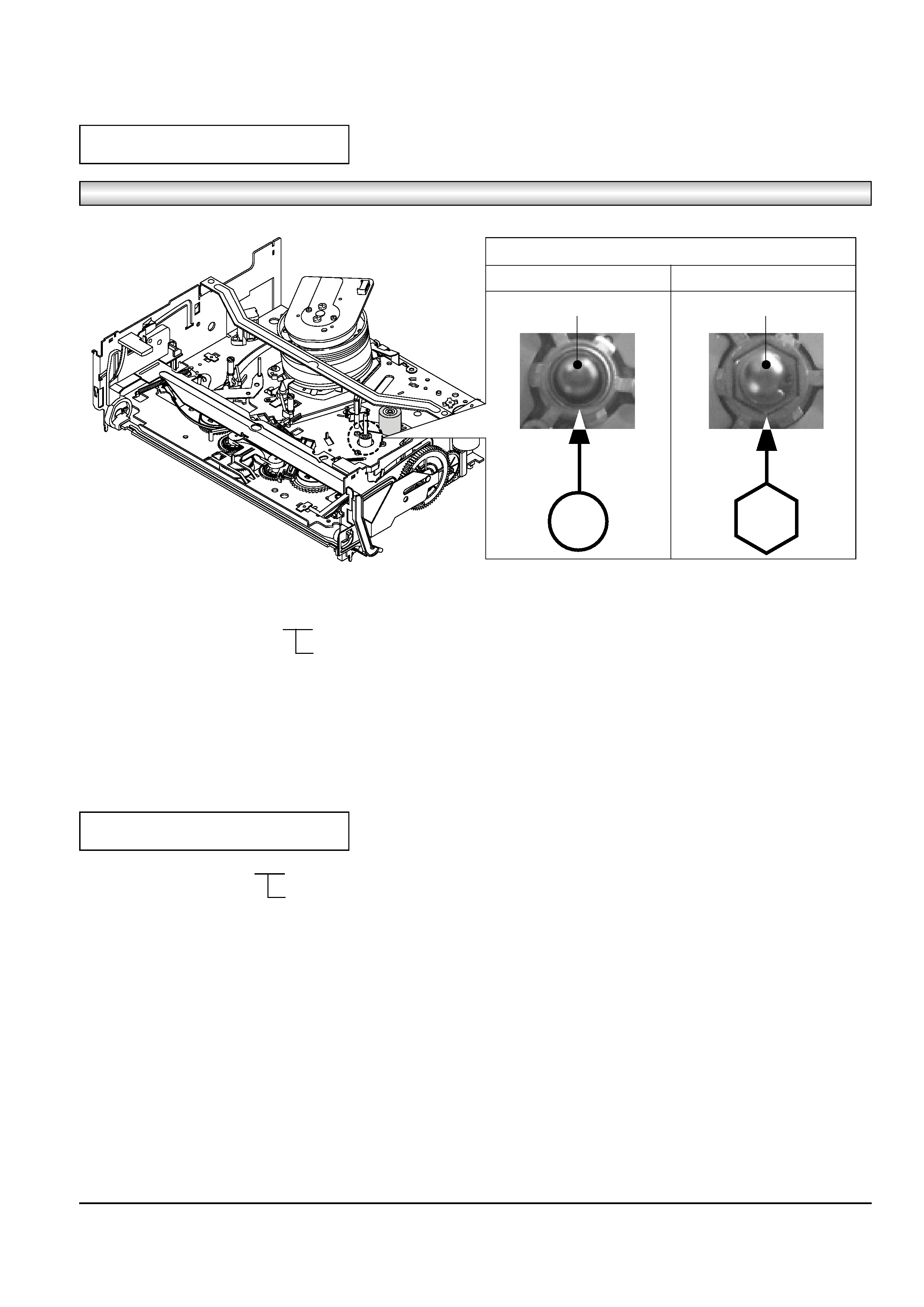
Assy Cylinder, the Capsrtan Motor & TM-Block are used for this model, as shown below.
Assy-Cylinder
How to identify the Assy-Cylinder
ALPS Cylinder
SEM Cylinder
CONNECTOR ; Pin 7 or Pin 5
CONNECTOR ; Pin 5
Fig. 1
1) Three kinds of the Assy-Cylinder as shown below.
OE ALPS Cylinder
´ SEM Cylinder
Connector ; Pin 7
Connector ; Pin 5
Connector ; Pin 5
2) When replacing the Assy-Cylinder, be sure to replace only "SEM Cylinder".
The only part-no of "SEM Cylinder" is shown in the "CH7. Replacement Parts List" of Service Manual.
3) When changing from ALPS (connector ; pin 7) cylinder to SEM (connector ; pin 5) cylinder.
- Change CN605 (Connector ; pin 7
pin 5)
- Change CN605B (Cable-Flat ; pin 7
pin 5)
4) After replacing the "SEM Cylinder", use type "C, D, G, H" optional for "NVRAM Option Setting". (See page 5-9)
The Maker of Assy Cylinder
1
2
ALPS
SEM
The Maker of Assy Capstan Motor
1
2
SANKYO
SEM
Two kinds of TM-Block
1
2
SIF available
Not SIF availablea
II
Toshiba
How to identify the Capstan Motor
TOP VIEW
SANKYO CAPSTAN MOTOR
SEM CAPSTAN MOTOR
CAPSTAN SHAFT
CAPSTAN SHAFT
Fig. 2
1) Two kinds of the Capstan Motor
OE Sankyo Capstan Motor
´ SEM Capstan Motor
2) When replacing the Capstan Motor, be sure to replace only "SEM Capstan Motor".
The only part-no of "SEM Capstan Motor" is shown in the "CH7. Replacement Parts List" of Service Manual.
3) After replacing the "SEM Capstan Motor", use type "E, F, G, H" optional for "NVRAM Option Setting". (See page 5-9)
Capstam Motor
TM-BLOCK
1) Two kinds of the TM-Blovk
OE SIF available
´ Not SIF available
2) How to identify TM-Block ; See page 5-11 (Fig. 5-21)
- In case there is VR501 ; Not SIF available
- In case there is no VR501 ; SIF available
3) When replacing the TM-Block as a service parts, be sure to replace only the TM-Block which is SIF available.
The only part-no of "SIF available" is shown in the "CH7. Replacement Parts List" of Service Manual.
4) After replacing "TM-Block", use type "B, D, F, H" optional for "NVRAM Option Setting" regardless of VR501. (See page 5-9)
Toshiba
1-1
1. Precautions
1. Be sure that all of the built-in protective devices are
replaced. Restore any missing protective shields.
2. When reinstalling the chassis and its assemblies, be
sure to restore all pretective devices, including :
control knobs and compartment covers.
3. Make sure that there are no cabinet openings
through which people--particularly children
--might insert fingers and contact dangerous
voltages. Such openings include the spacing
between the picture tube and the cabinet mask,
excessively wide cabinet ventilation slots, and
improperly fitted back covers.
If the measured resistance is less than 1.0 megohm
or greater than 5.2 megohms, an abnormality exists
that must be corrected before the unit is returned
to the customer.
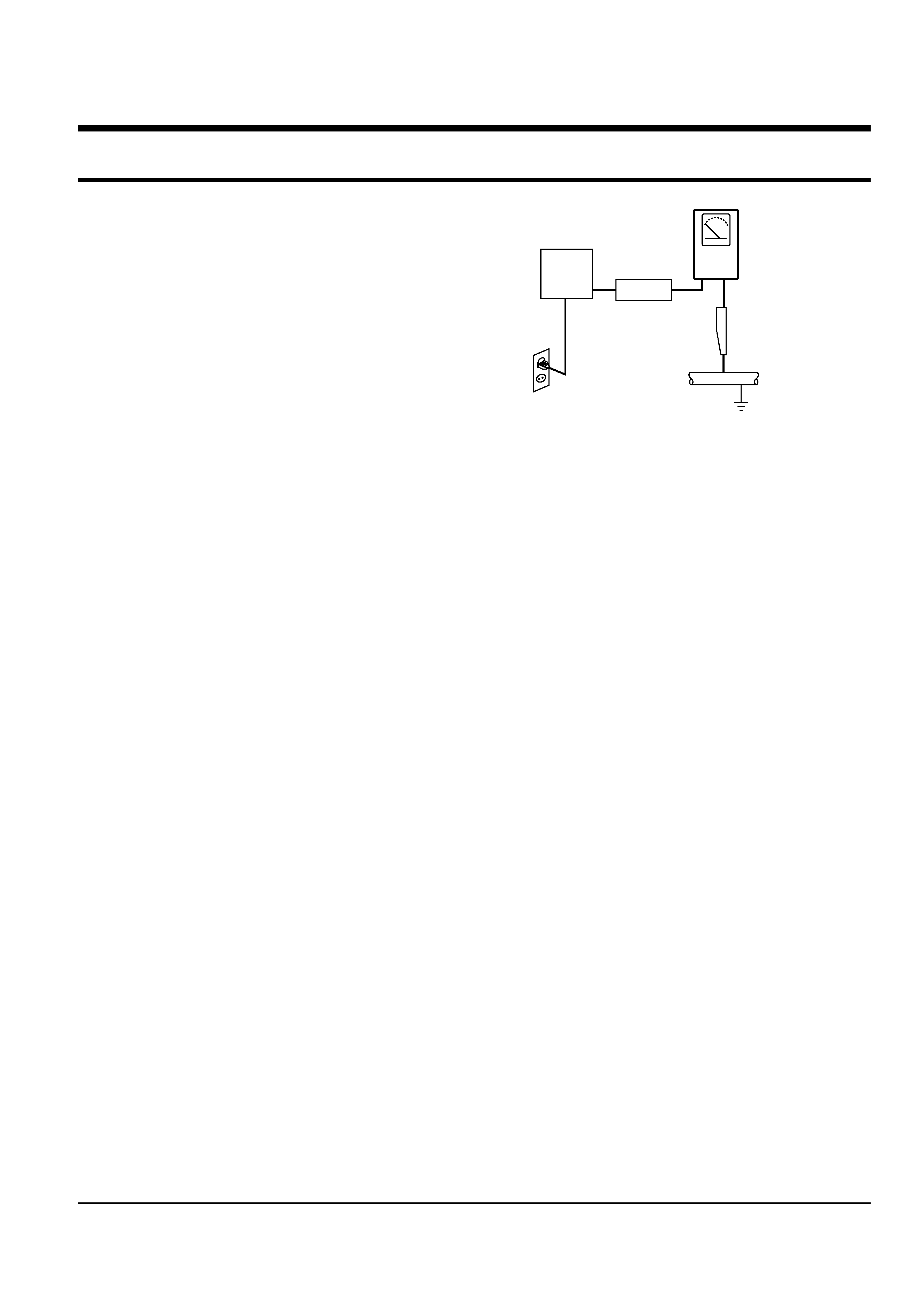
4. Leakage Current Hot Check (See Fig. 1-1) :
Warning : Do not use an isolation transformer
during this test. Use a leakage current tester or a
metering system that complies with American
National Standards Institute (ANSI C101.1,
Leakage Current for Appliances), and Underwriters
Laboratories (UL Publication UL1410, 59.7).
5. With the unit completely reassembled, plug the AC
line cord directly the power outlet. With the unit's
AC switch first in the ON position and then OFF,
measure the current between a known erath
ground (metal water pipe, conduit, etc.) and all
exposed metal parts, including : antennas, handle
brackets, metal cabinets, screwheads and control
shafts. The current measured should not exceed
0.5 milliamp. Reverse the power-plug prongs in the
AC outlet and repeat the test.
6. X-ray Limits :
The picture tube is designed to prohibit X-ray
emissions. To ensure continued X-ray protection,
replace the picture tube only with one that is the
same type as the original.
Fig. 1-1 AC Leakage Test
7. Antenna Cold Check :
With the unit's AC plug disconnected from the
AC source, connect an electrical jumper across the
two AC prongs. Connect one lead of the ohmmeter
to an AC prong.
Connect the other lead to the coaxial connector.
8. High Voltage Limit :
High voltage must be measured each time
servicing is done on the B+, horizontal deflection
or high voltage circuits.
Heed the high voltage limits. These include the
X-ray protection Specifications Label, and the
Product Safety and X-ray Warning Note on the
service data schematic.
9. Some semiconductor ("solid state") devices are
easily damaged by static electricity.
Such components are called Electrostatically
Sensitive Devices (ESDs); examples include
integrated circuits and some field-effect transistors.
The following techniques will reduce the
occurrence of component damage caused by static
electricity.
10. Immediately before handling any semiconductor
components or assemblies, drain the electrostatic
charge from your body by touching a known
earth ground. Alternatively, wear a discharging
Wrist-strap device. (Be sure to remove it prior to
applying power--this is an electric shock
precaution.)
DEVICE
UNDER
TEST
(READING SHOULD
NOT BE ABOVE
0.5mA)
LEAKAGE
CURRENT
TESTER
EARTH
GROUND
TEST ALL
EXPOSED METER
SURFACES
ALSO TEST WITH
PLUG REVERSED
(USING AC ADAPTER
PLUG AS REQUIRED)
2-WIRE CORD