
SERVICE MANUAL
FILE NO. 120-200205
VIDEO CASSETTE RECORDER
W-528
JAN, 2002
W-528
1/22/04
3:44 AM
Page 1

TOTAL CONTENTS
1. Precautions
2. Reference Information
3. Product Specifications
4. Disassembly and Reassembly
5. Alignment and Adjustment
6. Exploded View
7. Replacement Parts List
8. Block Diagram
9. PCB Diagrams
10. Schematic Diagrams
Toshiba
1-1
1. Precautions
1. Be sure that all of the built-in protective devices are
replaced. Restore any missing protective shields.
2. When reinstalling the chassis and its assemblies, be
sure to restore all pretective devices, including :
control knobs and compartment covers.
3. Make sure that there are no cabinet openings
through which people--particularly children
--might insert fingers and contact dangerous
voltages. Such openings include the spacing
between the picture tube and the cabinet mask,
excessively wide cabinet ventilation slots, and
improperly fitted back covers.
If the measured resistance is less than 1.0 megohm
or greater than 5.2 megohms, an abnormality exists
that must be corrected before the unit is returned
to the customer.
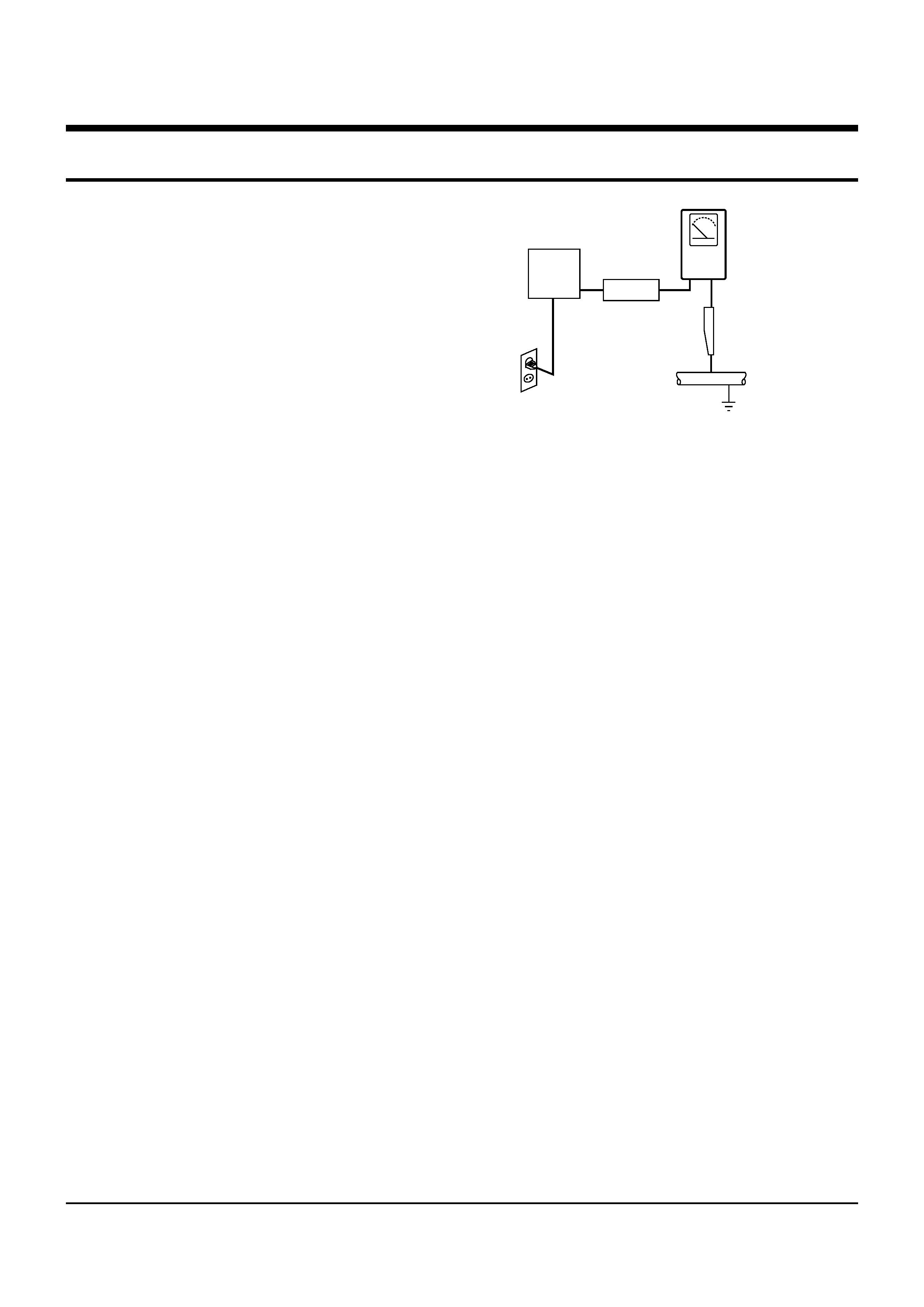
4. Leakage Current Hot Check (See Fig. 1-1) :
Warning : Do not use an isolation transformer
during this test. Use a leakage current tester or a
metering system that complies with American
National Standards Institute (ANSI C101.1,
Leakage Current for Appliances), and Underwriters
Laboratories (UL Publication UL1410, 59.7).
5. With the unit completely reassembled, plug the AC
line cord directly the power outlet. With the unit's
AC switch first in the ON position and then OFF,
measure the current between a known erath
ground (metal water pipe, conduit, etc.) and all
exposed metal parts, including : antennas, handle
brackets, metal cabinets, screwheads and control
shafts. The current measured should not exceed
0.5 milliamp. Reverse the power-plug prongs in the
AC outlet and repeat the test.
6. X-ray Limits :
The picture tube is designed to prohibit X-ray
emissions. To ensure continued X-ray protection,
replace the picture tube only with one that is the
same type as the original.
Fig. 1-1 AC Leakage Test
7. Antenna Cold Check :
With the unit's AC plug disconnected from the
AC source, connect an electrical jumper across the
two AC prongs. Connect one lead of the ohmmeter
to an AC prong.
Connect the other lead to the coaxial connector.
8. High Voltage Limit :
High voltage must be measured each time
servicing is done on the B+, horizontal deflection
or high voltage circuits.
Heed the high voltage limits. These include the
X-ray protection Specifications Label, and the
Product Safety and X-ray Warning Note on the
service data schematic.
9. Some semiconductor ("solid state") devices are
easily damaged by static electricity.
Such components are called Electrostatically
Sensitive Devices (ESDs); examples include
integrated circuits and some field-effect transistors.
The following techniques will reduce the
occurrence of component damage caused by static
electricity.
10. Immediately before handling any semiconductor
components or assemblies, drain the electrostatic
charge from your body by touching a known
earth ground. Alternatively, wear a discharging
Wrist-strap device. (Be sure to remove it prior to
applying power--this is an electric shock
precaution.)
DEVICE
UNDER
TEST
(READING SHOULD
NOT BE ABOVE
0.5mA)
LEAKAGE
CURRENT
TESTER
EARTH
GROUND
TEST ALL
EXPOSED METER
SURFACES
ALSO TEST WITH
PLUG REVERSED
(USING AC ADAPTER
PLUG AS REQUIRED)
2-WIRE CORD
Precautions
1-2
Toshiba
11. High voltage is maintained within specified limits
by close-tolerance, safety-related components and
adjustments. If the high voltage exceeds the
specified limits, check each of the special
components.
12. Design Alteration Warning :
Never alter or add to the mechanical or electrical
design of this unit. Example : Do not add
auxiliary audio or video connectors.
Such alterations might create a safety hazard.
Also, any design changes or additions will void
the manufacturer's warranty.
13. Hot Chassis Warning :
Some TV receiver chassis are electrically
connected directly to one conductor of the AC
power cord. If an isolation transformer is not
used, these units may be safely serviced only if
the AC power plug is inserted so that the chassis
is connected to the ground side of the AC source.
To confirm that the AC power plug is inserted
correctly, do the following : Using an AC
voltmeter, measure the voltage between the
chassis and a known earth ground. If the reading
is greater than 1.0V, remove the AC power plug,
reverse its polarity and reinsert. Re-measure the
voltage between the chassis and ground.
14. Some TV chassis are designed to operate with 85
volts AC between chassis and ground, regardless
of the AC plug polarity. These units can be safely
serviced only if an isolation transformer inserted
between the receiver and the power source.
15. Never defeat any of the B+ voltage interlocks.
Do not apply AC power to the unit (or any of its
assemblies) unless all solid-state heat sinks are
correctly installed.
16. Always connect a test instrument's ground lead to
the instrument chassis ground before connecting
the positive lead; always remove the instrument's
ground lead last.
17. Observe the original lead dress, especially near
the following areas : Antenna wiring, sharp
edges, and especially the AC and high voltage
power supplies. Always inspect for pinched, out-
of-place, or frayed wiring. Do not change the
spacing between components and the printed
circuit board. Check the AC power cord for
damage. Make sure that leads and components
do not touch thermally hot parts.
18. Picture Tube Implosion Warning :
The picture tube in this receiver employs
"integral implosion" protection. To ensure
continued implosion protection, make sure that
the replacement picture tube is the same as the
original.
19. Do not remove, install or handle the picture tube
without first putting on shatterproof goggles
equipped with side shields. Never handle the
picture tube by its neck. Some "in-line" picture
tubes are equipped with a permanently attached
deflection yoke; do not try to remove such
"permanently attached" yokes from the picture
tube.
20. Product Safety Notice :
Some electrical and mechanical parts have special
safety-related characteristics which might not be
obvious from visual inspection. These safety
features and the protection they give might be
lost if the replacement component differs from the
original--even if the replacement is rated for
higher voltage, wattage, etc.
Components that are critical for safety are
indicated in the circuit diagram by shading,
(
or
).
Use replacement components that have the same
ratings, especially for flame resistance and
dielectric strength specifications. A replacement
part that does not have the same safety
characteristics as the original might create shock,
fire or other hazards.
Toshiba
2-1
9
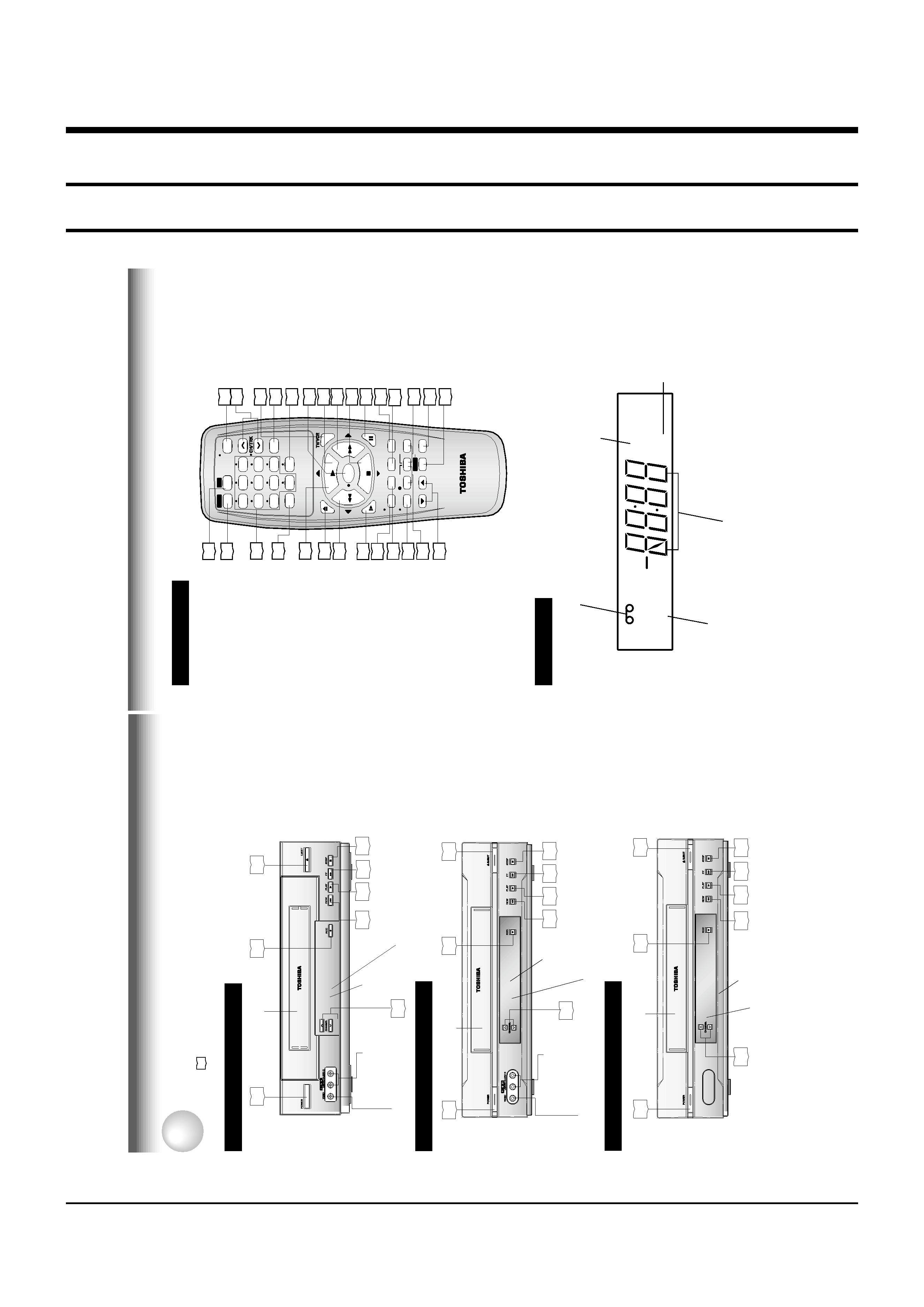
Remote
Contr
ol
*These
buttons
are
used
to
control
the
cursor
on
the
screen.
To
operate
your
TV.
To
operate
this
VCR.
SLOW
PAUSE
/STILL
REC
TIMER
TV
VCR
POWER
I.SELECT
SP/
SLP
DISPLA
Y
TV
VOL
COUNTER
PROG.
CANCEL
REMAIN/
RESET
COUNT
EJECT
CM
SKIP
30
20
20
22
17
19
15
1
2
3
6
5
4
10
0
9
8
7
0
ST
OP
FF
REW
PLA
Y
ENTER
25
23
25
23
30
A.SELECT
29
POWER
CH/TRK
CM
SKIP
100
ENTER
PLAY
*
FF
*
STOP
*
PROG.
CANCEL
TIMER
COUNT
RESET
SP/SLP
PAUSE/STILL
TV
VOL
REC
I.SELECT
REMAIN/COUNTER
DISPLAY
SLOW
REW
*
EJECT
PLAY
*
(For
W-522
only
)
A.SELECT
Number
buttons
VCR
TV
20
15
18
20
20
15
15
20
21
25
23
27
28
25
TV/VCR
21
Multifunctional
indicator
VCR
indicator
Cassette
indicator
Timer
recording
indicator
VCR
Display
VCR
TIMER
Hi-Fi
Hi-Fi
indicator
(For
W-522
only
)
8
Fr
ont
Panel
model
W
-522
INTRODUCTION
Fr
ont
Panel
model
W
-422
Fr
ont
Panel
model
W
-528
Identification
of
Controls
See
the
page
in
for
details.
This
manual
shows
the
names
of
buttons
in
italics.
POWER
EJECT
15
25
20
20
20
20
25
19
Cassette
compartment
REC
VCR
Display
Remote
Sensor
CHANNEL
STOP
PLAY
FF
REW
15
25
25
19
20
20
20
20
REC
EJECT
CHANNEL
VCR
Display
Cassette
compartment
LINE
IN
2
VIDEO
jack
LINE
IN
2
AUDIO
(L/MONO,
R)
jacks
POWER
STOP
PLAY
FF
REW
Remote
Sensor
15
25
25
19
20
20
20
20
POWER
Cassette
compartment
REC
EJECT
LINE
IN
2
AUDIO
(L/MONO,
R)
jacks
LINE
IN
2
VIDEO
jack
CHANNEL
STOP
PLAY
FF
REW
Remote
Sensor
VCR
Display
2. Reference Information
2-1 Operation of Controls