Photo: SLV-SE830N
RMT-V407A
-- Continued on next page --
AEP Model
SLV-SE230B/SE230D/SE430K/SE630B/SE630D/SE630E/SE630N/
SE730B/SE730D/SE730E/SE730N/SE737E/SE830B/SE830D/
SE830E/SE830N/SX730D/SX730E/SX730N/SX737D
UK Model
SLV-SE230G/SE230I/SE730G/SE730I/SE830G
SERVICE MANUAL
VIDEO CASSETTE RECORDER
TS-10 MECHANISM
Refer to the SERVICE MANUAL of VHS MECHANI-
CAL ADJUSTMENT MANUAL VII for MECHANICAL
ADJUSTMENTS. (9-921-790-11)
SPECIFICATIONS
SLV-SE230/SE430/SE630/SE730/SE737/
SE830/SX730/SX737
RMT-V405/V405A/V406/V406A/V406B/V407A/V407B/V407C
System
Colour system
SE230B/SE630B/SE730B/SE830B:
SECAM (L)
VHF F2 to F10
UHF F21 to F69
CATV B to Q
HYPER S21 to S41
PAL (B/G)
VHF E2 to E12
VHF italian channels A to H
UHF E21 to E69
CATV S01 to S05, S1 to S20
HYPER S21 to S41
SE230D/SE630D/SE630E/SE730D/SE730E/
SE737E/SE830D/SE830E/SX730D/SX730E/
SX737D:
PAL (B/G)
VHF E2 to E12
VHF italian channels A to H
UHF E21 to E69
CATV S01 to S05, S1 to S20
HYPER S21 to S41
SE230G/SE730G/SE830G:
PAL (I)
UHF B21 to B69
SE230I/SE730I:
PAL (I)
VHF IA to IJ, SA10 to SA13
UHF B21 to B69
CATV S01 to S05, S1 to S20
HYPER S21 to S41
SE430K/SE630N/SE730N/SE830N/SX730N:
PAL (B/G, D/K)
VHF E2 to E12, R1 to R12
UHF E21 to E69, R21 to R69
CATV S1 to S41, S01 to S05
RF output signal
SE230D/SE230G/SE230I/SE430K/SE630D/
SE630E/SE630N/SE730D/SE730E/SE730G/
SE730I/SE730N/SE737E/SE830D/SE830E/
SE830G/SE830N/SX730D/SX730E/SX730N/
SX737D:
UHF channels 21 to 69
Aerial out
75-ohm asymmetrical aerial socket
Tape speed
SE230B:
SP: PAL
23.39 mm/s (recording/playback)
NTSC 33.35 mm/s (playback only)
SECAM
23.39 mm/s (recording/playback)
MESECAM
23.39 mm/s (playback only)
LP: NTSC 16.67 mm/s (playback only)
SECAM
11.70 mm/s (recording/playback)
MESECAM
11.70 mm/s (playback only)
SE230D:
SP: PAL
23.39 mm/s (recording/playback)
NTSC 33.35 mm/s (playback only)
LP: NTSC 16.67 mm/s (playback only)
SE230G/SE230I/SE630D/SE630E/SE730D/
SE730E/SE730G/SE730I/SE737E/SE830D/
SE830E/SE830G/SX730D/SX730E/SX737D:
SP: PAL
23.39 mm/s (recording/playback)
NTSC 33.35 mm/s (playback only)
LP: PAL
11.70 mm/s (recording/playback)
NTSC 16.67 mm/s (playback only)
EP: NTSC 11.12 mm/s (playback only)

-- 2 --
SAFETY CHECK-OUT
1. Check the area of your repair for unsoldered or poorly-soldered
connections. Check the entire board surface for solder splashes
and bridges.
2. Check the interboard wiring to ensure that no wires are
"pinched" or contact high-wattage resistors.
3. Look for unauthorized replacement parts, particularly transistors,
that were installed during a previous repair. Point them out to
the customer and recommend their replacement.
After correcting the original service problem, perform the following
safety checks before releasing the set to the customer:
4. Look for parts which, though functioning, show obvious signs
of deterioration. Point them out to the customer and recommend
their replacement.
5. Check the B+ voltage to see it is at the values specified.
SAFETY-RELATED COMPONENT WARNING!!
COMPONENTS IDENTIFIED BY MARK 0 OR DOTTED
LINE WITH MARK 0 ON THE SCHEMATIC DIAGRAMS
AND IN THE PARTS LIST ARE CRITICAL TO SAFE
OPERATION. REPLACE THESE COMPONENTS WITH
SONY PARTS WHOSE PART NUMBERS APPEAR AS
SHOWN IN THIS MANUAL OR IN SUPPLEMENTS
PUBLISHED BY SONY.
SE430K/SE630N/SE730N/SE830N/SX730N:
SP: PAL/MESECAM
23.39 mm/s (recording/playback)
NTSC 33.35 mm/s (playback only)
LP: PAL/MESECAM
11.70 mm/s (recording/playback)
NTSC 16.67 mm/s (playback only)
EP: NTSC 11.12 mm/s (playback only)
SE630B/SE730B/SE830B:
SP: PAL
23.39 mm/s (recording/playback)
NTSC 33.35 mm/s (playback only)
SECAM
23.39 mm/s (recording/playback)
MESECAM
23.39 mm/s (playback only)
LP: PAL
11.70 mm/s (recording/playback)
NTSC 16.67 mm/s (playback only)
SECAM
11.70 mm/s (recording/playback)
MESECAM
11.70 mm/s (playback only)
EP: NTSC 11.12 mm/s (playback only)
Maximum recording/playback time
10 hrs. in LP mode (with E300 tape)
Rewind time
Approx. 1 min.(with E180 tape)
Inputs and outputs
LINE-1 (EURO AV)
21-pin
Video input: pin 20
Audio input: pins 2 and 6
Video output: pin 19
Audio output: pins 1 and 3
LINE-2 (DEC/EXT)/LINE-3 (DEC/EXT)
21-pin
Video input: pin 20
Audio input: pins 2 and 6
SE830B/SE830D/SE830E/SE830G/SE830N:
t LINE-2 L o R
VIDEO IN, phono jack (1)
Input signal: 1 Vp-p, 75 ohms,
unbalanced, sync negative
AUDIO IN, phono jack (2)
Input level: 327 mVrms
Input impedance: more than 47 kilohms
SE730B/SE730D/SE730E/SE730G/SE730I/
SE730N/SE737E/SE830B/SE830D/SE830E/
SE830G/SE830N/SX730D/SX730E/SX730N/
SX737D:
AUDIO (OUT/SORTIE) R/D L/G
Phono jack (2)
Rated output level: 327 mVrms
Load impedance: 47 kilohms
Output impedance: less than 10 kilohms
General
Power requirements
220 240 V AC, 50 Hz
Power consumption
SE230B/SE230D/SE230G/SE230I/SE430K:
15 W
1.2 W (POWER SAVE is set to ECO2, minimum)
SE630B/SE630D/SE630E/SE630N:
17 W
1.2 W (POWER SAVE is set to ECO2, minimum)
SE730B/SE730D/SE730ESE730G/SE730I/
SE730N/SE737E/SE830B/SE830D/SE830E/
SE830G/SE830N/SX730D/SX730E/SX730N/
SX737D:
17 W
1.3 W (POWER SAVE is set to ECO2, minimum)
Operating temperature
5
°C to 40 °C
Storage temperature
20
°C to 60 °C
Dimensions including projecting parts and controls (w/h/
d)
SE230B/SE230D/SE230G/SE230I/SE430K:
Approx. 360
× 95 × 245 mm
SE630B/SE630D/SE630E/SE630N/SE730B/
SE730D/SE730E/SE730G/SE730I/SE730N/
SE737E/SX730D/SX730E/SX730N/SX737D:
Approx. 430
× 96 × 245 mm
SE830B/SE830D/SE830E/SE830G/SE830N:
Approx. 430
× 96 × 253 mm
Mass
SE230B/SE230D/SE230G/SE230I/SE430K:
Approx. 2.8 kg
SE630B/SE630D/SE630E/SE630N/SE730B/
SE730D/SE730E/SE730G/SE730I/SE730N/
SE737E/SE830B/SE830D/SE830E/SE830G/
SE830N/SX730D/SX730E/SX730N/SX737D:
Approx. 3.1 kg
Supplied accessories
Remote commander (1)
R6 (size AA) batteries (2)
Aerial cable (1)
SE230B/SE630B/SE730B/SE830B:
PERITEL cable (1)
Design and specifications are subject to change without
notice.

-- 3 --
TABLE OF CONTENTS
Important Service Guide
Mode Switch (Program Switch) Assembly Point ························· 4
How to eject the cassette tape
(If the unit does not operate on condition that tape is inserted
into housing ass'y) ································································· 4
1.
General
Getting Started
Index to parts and controls ················································· 1-1
Step 1 : Unpacking ····························································· 1-2
Step 2 : Setting up the remote commander ························· 1-3
Step 3 : Connecting the VCR ············································· 1-4
Step 4 : Setting up the VCR with the Auto
Set Up function ····················································· 1-5
Step 5 : Selecting the TV system ········································ 1-5
Setting the clock ···················································· 1-6
Downloading the TV tuner's preset data ··············· 1-6
Selecting a language ·············································· 1-6
Presetting channels ················································ 1-7
Changing/disabling programme positions ············· 1-7
Setting the Canal Plus decoder ······························ 1-9
Basic Operations
Playing a tape ····································································· 1-9
Recording TV programmes ·············································· 1-10
Recording TV programmes using the Dial Timer ············ 1-11
Recording TV programmes using
the Show ViewR system ···················································· 1-12
Recording TV programmes using the timer ····················· 1-13
Additional Operations
Playing/searching at various speeds ································· 1-14
Setting the recording duration time ·································· 1-15
Checking/changing/cancelling timer settings ··················· 1-15
Recording stereo and bilingual programmes ···················· 1-15
Searching using the index function ·································· 1-16
Adjusting the picture ························································ 1-17
Reducing the VCR's power consumption ························ 1-17
Changing menu options ···················································· 1-17
Editing
Connecting to a VCR or stereo system ····························· 1-18
Basic editing ····································································· 1-18
Audio dubbing ·································································· 1-18
Additional Information
Troubleshooting ································································ 1-19
Index ················································································· 1-20
Quick Start Guide ······································································· 1-20
2.
Disassembly
2-1
Mono Models
2-1-1 Cabinet Top ········································································ 2-1
2-1-2 Cover Bottom ····································································· 2-1
2-1-3 Ass'y-Panel Front ······························································· 2-2
2-1-4 Ass'y Main PCB, Deck ······················································ 2-3
2-2
Hi-Fi Models
2-2-1 Cabinet Top ········································································ 2-4
2-2-2 Cover Bottom ····································································· 2-4
2-2-3 Ass'y-Panel Front ······························································· 2-5
2-2-4 Ass'y Jack PCB ·································································· 2-5
2-2-5 Ass'y Main PCB, Deck ······················································ 2-6
3.
P.C.Boards
3-1
Main PCB (Main A model) ················································ 3-3
3-2
Main PCB (Main B model) ················································ 3-7
3-3
Function PCB (Hi-Fi model) ············································ 3-11
3-4
Dial Timer PCB (SE830) ·················································· 3-11
4.
Schematic Diagrams
Block Identification of Main PCB ············································ 4-3
4-1
S.M.P.S. (Main A model) ··················································· 4-5
4-2
S.M.P.S. (Main B model) ··················································· 4-7
4-3
Power (Main A model) ······················································· 4-9
4-4
Power (Main B model) ····················································· 4-11
4-5
System Control/Servo (Main A model) ···························· 4-13
4-6
System Control/Servo (Main B model) ···························· 4-15
4-7
Audio/Video ····································································· 4-17
4-8
Hi-Fi (Hi-Fi model) ·························································· 4-19
4-9
TM-Block ········································································· 4-21
4-10 OSD/VPS/PDC ································································· 4-23
4-11 SECAM (SE230B/SE630B/SE730B/SE830B) ················ 4-25
4-12 A2/NICAM (Hi-Fi model) ··············································· 4-27
4-13 Input-Output (2 Scart Jack) (Main A model) ··················· 4-29
4-14 Input-Output (2 Scart Jack) (Main B model) ··················· 4-31
4-15 Function (SE630) ····························································· 4-33
4-16 Function (Main B model) ················································· 4-35
5.
Alignment and Adjustment
5-1
Reference ············································································ 5-1
5-1-1 Location of adjustment button of remote control ··············· 5-1
5-1-2 Test point location for adjustment mode setting
(Mono model) ····································································· 5-2
5-1-3 SW7T01 (TEST) location for adjustment mode setting
(Hi-Fi model) ······································································ 5-3
5-2
Mechanical Adjustment ······················································ 5-4
5-2-1 The number and position of test point ································ 5-4
5-2-2 ACE Head Position (X-Point) Adjustment ························· 5-4
5-3
Head Switching Point Adjustment ····································· 5-5
5-4
NVRAM Option Setting ····················································· 5-5
6.
Repair Parts List
6-1
Exploded Views ·································································· 6-2
6-1-1 Instrument Assembly (Mono Models) ································ 6-2
6-1-2 Instrument Assembly (Hi-Fi Models) ································· 6-3
6-1-3 Mechanical Parts (Top Side) ·············································· 6-4
6-1-4 Mechanical Parts (Bottom Side) ········································· 6-5
6-2
Electrical Parts List ···························································· 6-6
· Main A model: SE230/SE430/SE630
Main B model: SE730/SE737/SE830/SX730/SX737
Hi-Fi model:
SE630/SE730/SE737/SE830/SX730/SX737
Mono model: SE230/SE430
-- 4 --
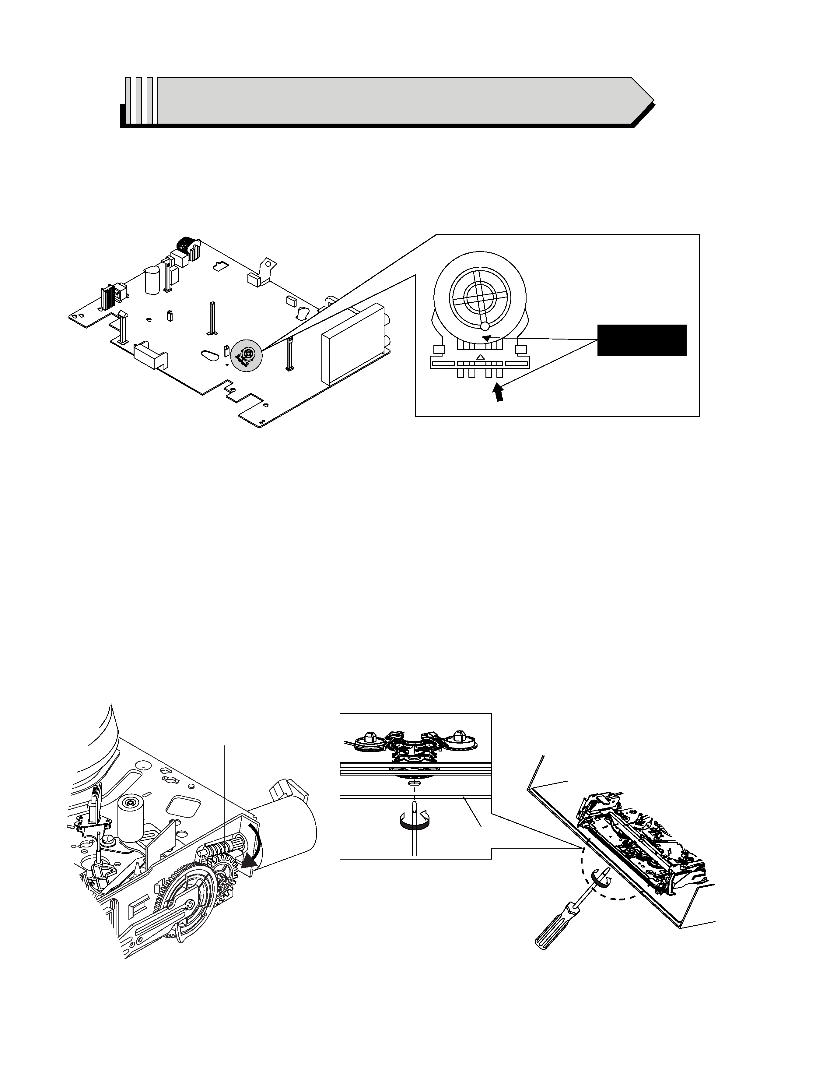
IMPORTANT SERVICE GUIDE
MODE SWITCH (PROGRAM SWITCH) ASSEMBLY POINT
1) When installing the ass'y deck on the Main PCB, be sure to align the assembly point of mode switch.
ASSEMBLY POINT
(ALIGN TWO ARROWS)
Fig. 1
Fig. 2
1
GEAR WORM
Fig. 3
FRAME
HOW TO EJECT THE CASSETTE TAPE
(If the unit does not operate on condition that tape is inserted into housing ass'y)
1) Turn the Gear Worm 1 clockwise in the direction of arrow with screw driver. (See Fig. 2)
(Other method ; Remove the screw of Motor Load Ass'y, Separate the Motor Load Ass'y)
2) When Slider S, T are approached in the position of unloading, rotate holder Clutch counterclockwise after inserting screw driver in the
hole of frame's bottom in order to wind the unwiunded tape. (Refer to Fig. 3)
(If you rotate Gear Worm 1 continuously when tape is in state of unwinding, you may cause a tape contamination by grease and
tape damage. Be sure to wind the unwiunded tape in the state of set horizontally.)
3) Rotate Gear Worm 1 clockwise using screw driver again up to the state of eject mode and then pick out the tape. (Refer to Fig. 2)
1-1
4 Index to parts and controls
Getting Started
Index to parts and controls
Refer to the pages indicated in parentheses ( ) for details.
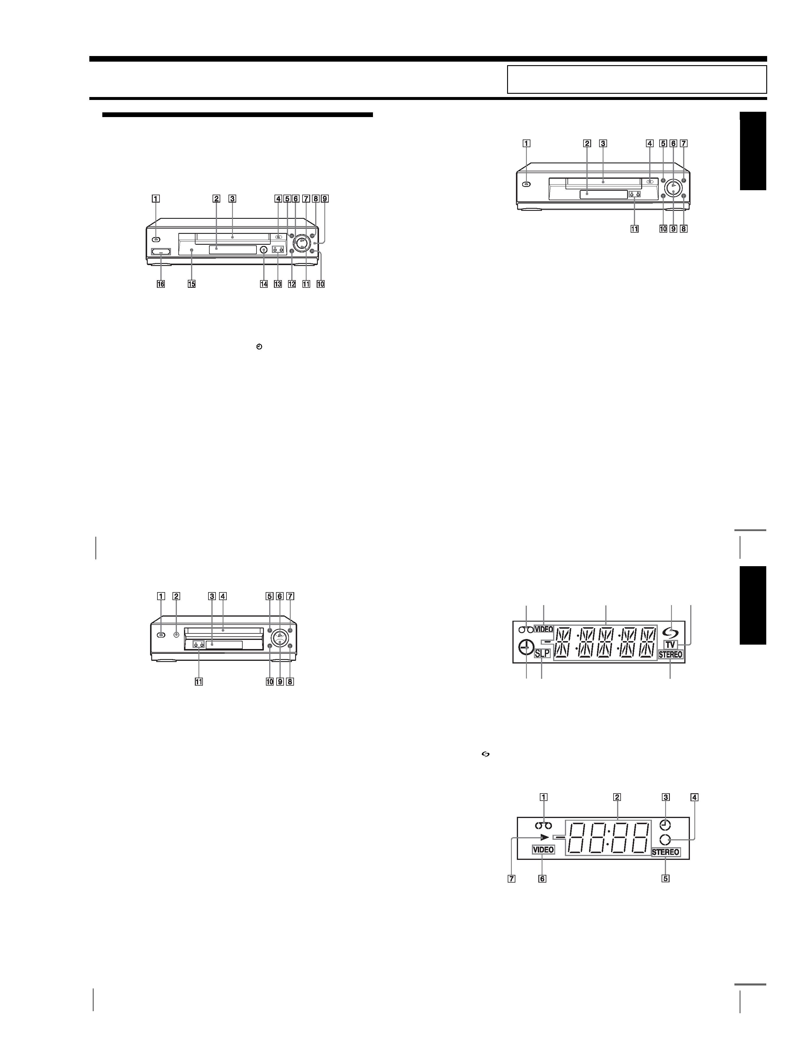
Front panel
For SLV-SE830N
A ?/1 (on/standby) switch
B Remote sensor (12)
C Tape compartment
D A (eject) button (39)
E m (rewind) button (39) (58)
F Shuttle ring (58)
G H (play) button* (39) (58)
H M (fast-forward) button (39) (58)
I JOG button (58)
J REC z (record) button (43) (60)
(74)
K x (stop) button* (22) (39) (74) (75)
L X (pause) button (39) (50) (74) (75)
M PROGRAM +/ buttons* (47) (59)
(68)
N
DIAL TIMER (46)
O AUDIO DUB button (75)
P t LINE-2 L (left) o R (right)
jacks (covered)* (72) (73) (75)
How to open the jack cover
1 Press the bottom of the cover.
2 Hook your finger on the top edge of the
cover and pull it open.
*The H (play), x (stop) and
PROGRAM + buttons and jack cover
have a tactile dot.
Getting
Star
ted
5
Index to parts and controls
For SLV-SE730N, SX730N and SE630N
A ?/1 (on/standby) switch
B Remote sensor (12)
C Tape compartment
D A (eject) button (39)
E m (rewind) button (39) (58)
F H (play) button* (39) (58)
G M (fast-forward) button (39) (58)
H REC z (record) button (43) (60)
(74)
I x (stop) button* (22) (39) (74) (75)
J X (pause) button (39) (74) (75)
K PROGRAM +/ buttons* (59) (68)
*The H (play), x (stop) and
PROGRAM + buttons have a tactile dot.
continued
6 Index to parts and controls
For SLV-SE430K
A ?/1 (on/standby) switch
B A (eject) button (39)
C Remote sensor (12)
D Tape compartment
E m (rewind) button (39) (58)
F H (play) button* (39) (58)
G M (fast-forward) button (39) (58)
H REC z (record) button (43) (60)
(74)
I x (stop) button* (22) (39) (74) (75)
J X (pause) button (39) (74) (75)
K PROGRAM +/ buttons* (59) (68)
*The H (play), x (stop) and
PROGRAM + buttons have a tactile dot.
Getting
Star
ted
7
Index to parts and controls
Display window
For SLV-SE830N, SE730N and SX730N
A Tape indicator
B VIDEO indicator (17) (43)
C Time counter/clock/line/programme
position indicator (40) (42) (74)
D
(smartlink) indicator (18)
E TV indicator (45)
F STEREO indicator (63)
G Tape speed indicators (42)
H Timer/recording indicator (43) (48)
(53) (56)
For SLV-SE630N and SE430K
A Tape indicator
B Time counter/clock/line/programme
position indicator (40) (42) (74)
C Timer indicator (48) (53) (56)
D Recording indicator (43)
E STEREO indicator* (63)
F VIDEO indicator (17) (43)
G Playback indicator
* not available on SLV-SE430K
3
1
45
2
6
7
8
continued
1. GENERAL
SLV-SE230/SE430/SE630/SE730/
SE737/SE830/SX730/SX737
This section is extracted from SLV-SE430K/SE630N/SE730N/
SE830N/SX730N instruction manual. (3-081-623-11)