SLV-GA30/GA40K/GA60/GA77K/GF90K
RMT-V254/V254A
E Model
Tourist Model
SLV-GA60/GA77K/GF90K
Philippine Model
SLV-GA30/GA40K
SERVICE MANUAL
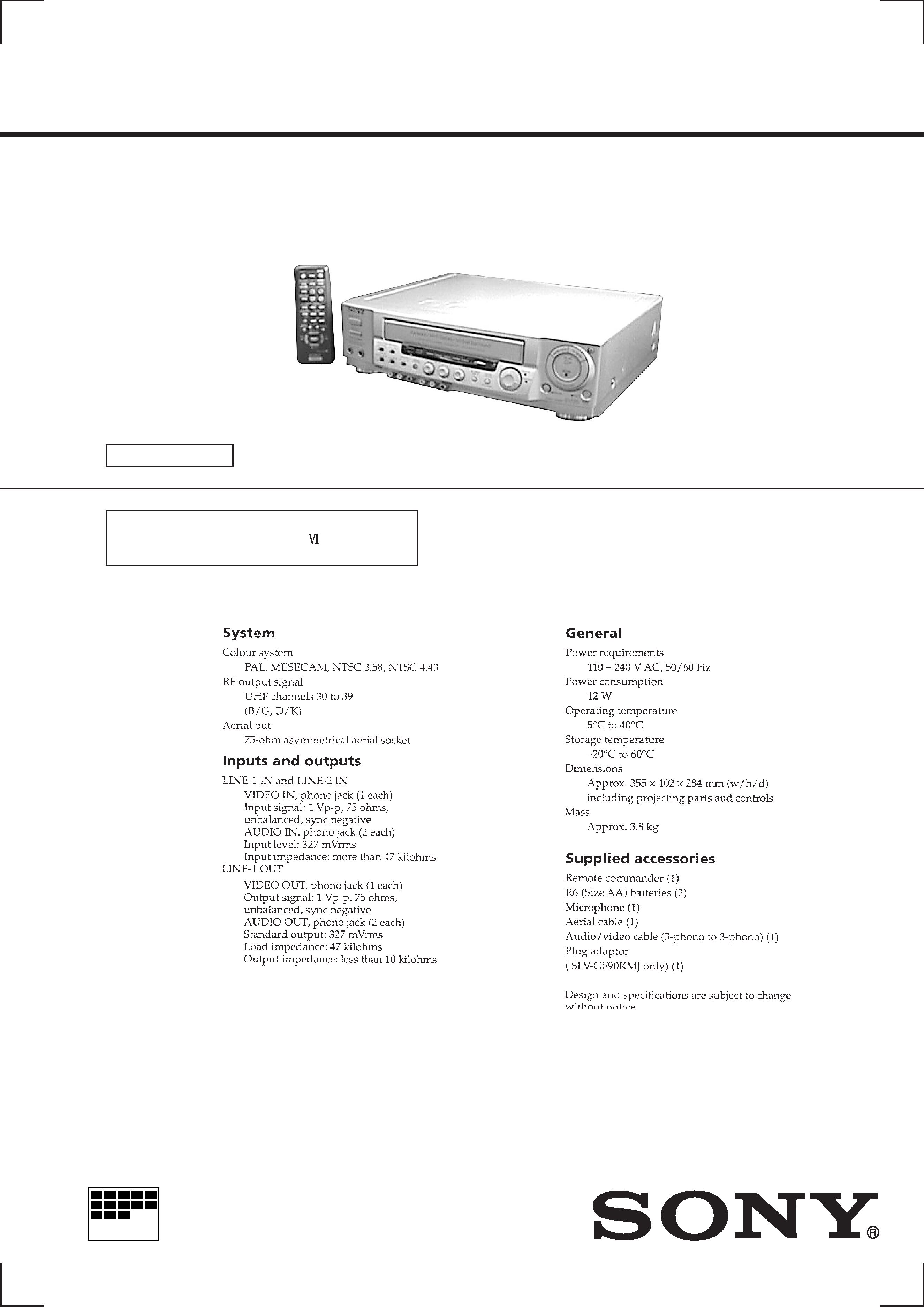
VIDEO CASSETTE PLAYER
MICROFILM
S MECHANISM
Refer to the SERVICE MANUAL of VHS
MECHANICAL ADJUSTMENT
for
MECHANICAL ADJUSTMENTS. (9-921-647-11)
SPECIFICATIONS
G
j
Photo: SLV-GA77K
RMT-V254

-- 2 --
SAFETY-RELATED COMPONENT WARNING!!
COMPONENTS IDENTIFIED BY MARK
! OR DOTTED LINE WITH
MARK
! ON THE SCHEMATIC DIAGRAMS AND IN THE PARTS
LIST ARE CRITICAL TO SAFE OPERATION. REPLACE THESE
COMPONENTS WITH SONY PARTS WHOSE PART NUMBERS
APPEAR AS SHOWN IN THIS MANUAL OR IN SUPPLEMENTS
PUBLISHED BY SONY.
1.
Check the area of your repair for unsoldered or poorly-soldered
connections. Check the entire board surface for solder splashes
and bridges.
2.
Check the interboard wiring to ensure that no wires are
"pinched" or contact high-wattage resistors.
3.
Look for unauthorized replacement parts, particularly
transistors, that were installed during a previous repair. Point
them out to the customer and recommend their replacement.
4.
Look for parts which, through functioning, show obvious signs
of deterioration. Point them out to the customer and
recommend their replacement.
5.
Check the B+ voltage to see it is at the values specified.
6.
Flexible Circuit Board Repairing
· Keep the temperature of the soldering iron around 270°C
during repairing.
· Do not touch the soldering iron on the same conductor of the
circuit board (within 3 times).
· Be careful not to apply force on the conductor when soldering
or unsoldering.
SAFETY CHECK-OUT
After correcting the original service problem, perform the following
safety checks before releasing the set to the customer.
-- 3 --
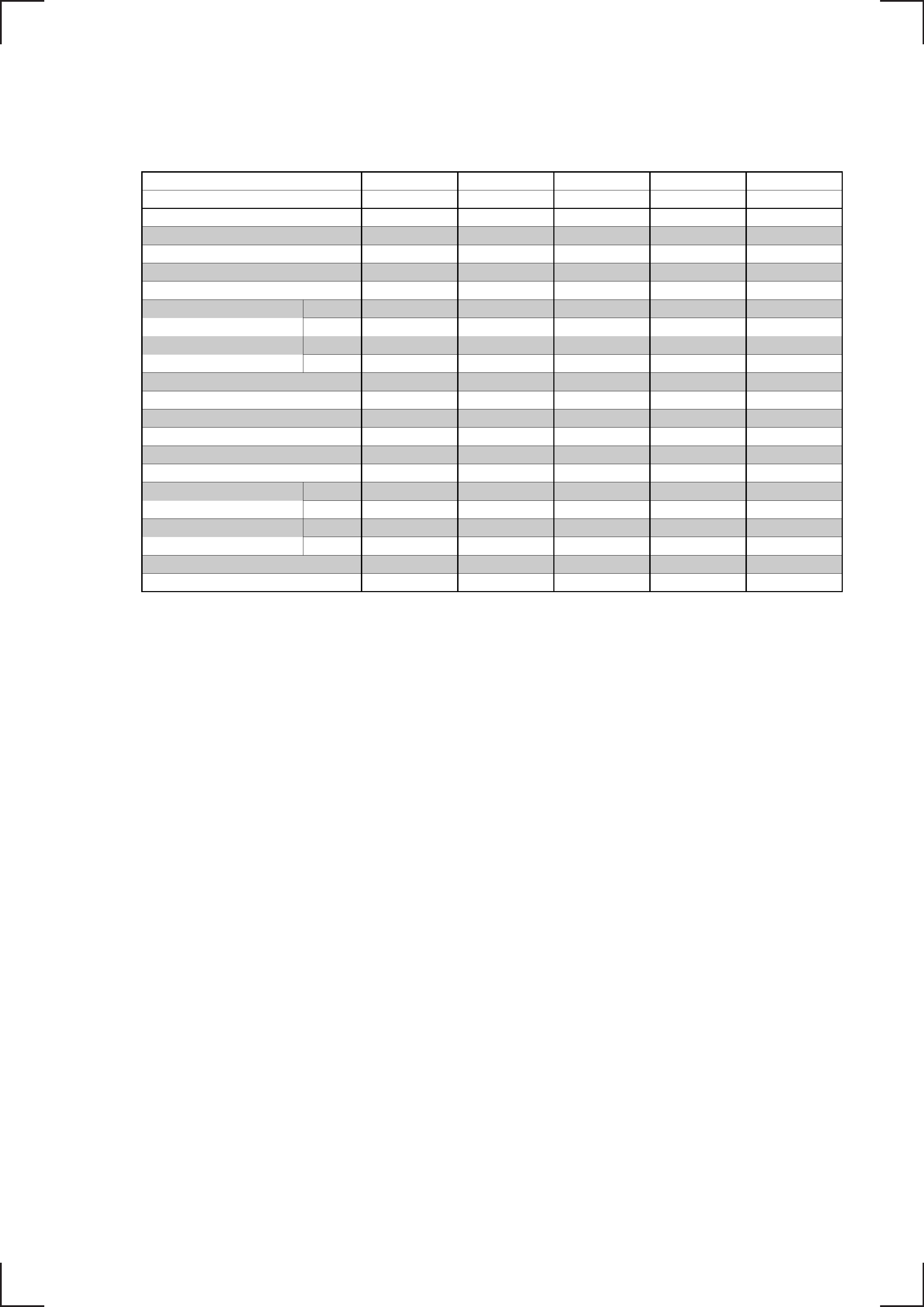
Abbreviation
MJ: E, Tourist Model
PL: Philippine Model
MODEL (SLV-)
GA30
GA40K
GA60
GA77K
GF90K
FEATURES
PL
PL
MJ
MJ
MJ
NTSC 3.58 REC/PB
X/O
X/O
O/O
O/O
NTSC 4.43 REC/PB
X/X
X/X
O/O
O/O
O/O
PAL REC/PB
X/X
X/X
O/O
O/O
O/O
MESECAM REC/PB
X/X
X/X
O/O
O/O
O/O
NTSC PB ON PAL TV
X
X
O
O
O
REC MODE
NTSC
X
X
SP/EP
SP/EP
SP
PAL
X
X
SP/LP
SP/LP
SP
PLAY MODE
NTSC
SP/LP/EP
SP/LP/EP
SP/LP/EP
SP/LP/EP
SP
PAL
X
X
SP/LP
SP/LP
SP
AUDIO SYSTEM
MONO
MONO
MONO
MONO
Hi-Fi
KARAOKE
X
O
X
O
O
KARAOKE PON
X
X
X
O
O
SOUNDS IN STEREO
XXXXX
SURROUND
X
X
X
O
X
TAPE SPEED
O
X
O
O
X
LINE IN (RCA PINS)
FRONT
X
X
X
3
3
REAR
X
X
2
3
3
LINE OUT(RCA PINS)
FRONT
X
X
X
3
X
REAR
22233
RF IN/OUT
USA
USA
GK
GK
GK
REMOTE COMMANDER
RMT-V254A
RMT-V254A
RMT-V254
RMT-V254
RMT-V254

-- 4 --
TABLE OF CONTENTS
1.
GENERAL
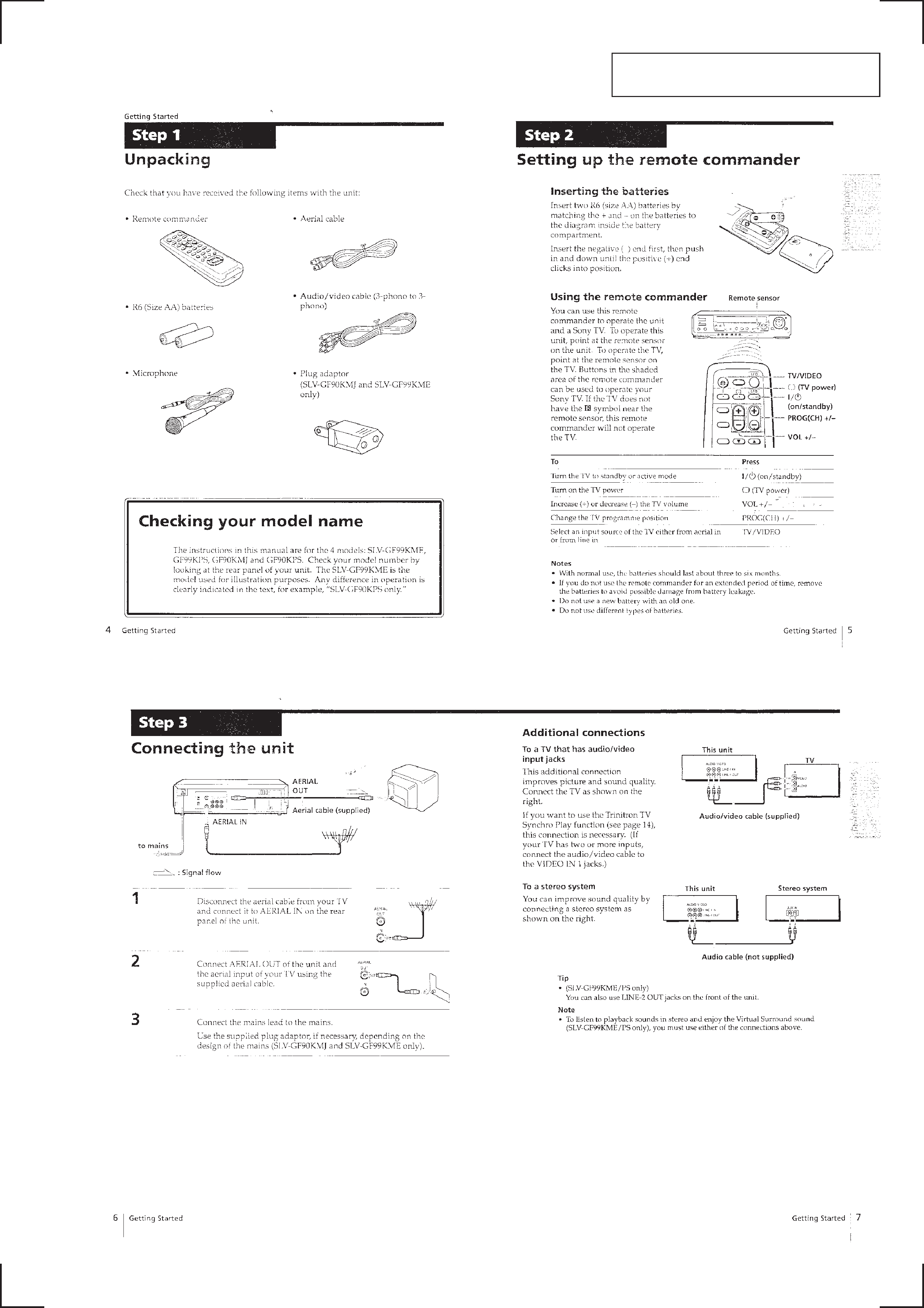
Step 1 Unpacking ······································································ 1-1
Step 2 Setting up the remote commander ·································· 1-1
Step 3 Connecting the unit ························································ 1-1
Step 4 Tuning your TV to the unit ············································· 1-2
Playing a tape ············································································ 1-2
Playing/searching at various speeds ·········································· 1-3
Karaoke sing-along ···································································· 1-4
Adjusting the picture (Resolution Control) ······························· 1-5
Editing with another VCR ························································· 1-5
Synchronised recording ····························································· 1-6
Troubleshooting ········································································· 1-6
Index to parts and controls ························································ 1-7
2.
DISASSEMBLY
2-1.
Upper Case, Panel Block Assembly ································ 2-1
2-2.
FR-140, 141, 142, JK-166, MJ-91 Boards ······················ 2-1
2-3.
Rear Panel ········································································ 2-2
2-4.
MA-336 Board ································································ 2-2
2-5.
Mechanism Deck ····························································· 2-3
2-6.
Internal Views ·································································· 2-4
2-7.
Circuit Boards Location ·················································· 2-5
3.
BLOCK DIAGRAMS
3-1.
Overall Block Diagram ··················································· 3-1
3-2.
Video Block Diagram ······················································ 3-3
3-3.
Servo/System Control Block Diagram ···························· 3-5
3-4.
Audio Block Diagram ····················································· 3-7
3-5.
Karaoke Block Diagram ·················································· 3-9
3-6.
Power Supply Block Diagram ······································· 3-11
4.
PRINTED WIRING BOARDS AND
SCHEMATIC DIAGRAMS
4-1.
Frame Schematic Diagram ·············································· 4-3
4-2.
Printed Wiring Boards and Schematic Diagrams ············ 4-5
· MA-336 (Video, Audio)(1/4) Schematic Diagram ······· 4-5
· MA-336 (Servo/System Control)(2/4)
Schematic Diagram ········································· 4-7
· MA-336 (HiFi, Tuner)(3/4) Schematic Diagram ·········· 4-9
· MA-336 (Karaoke, Power Supply)(4/4)
Schematic Diagram ······································· 4-11
· MA-336 (Video, Audio, Servo/System Control, Tuner,
Karaoke, Power Supply) Printed Wiring Board ·········· 4-13
· SR-35 (Surround) Printed Wiring Board ···················· 4-16
· SR-35 (Surround) Schematic Diagram ······················· 4-17
· FR-142 (Mode Control) Printed Wiring Board ··········· 4-19
· FR-142 (Mode Control) Schematic Diagram ············· 4-21
· FR-140 (Power, Eject Switches)
Printed Wiring Board and
Schematic Diagram ······································· 4-23
· FR-141 (Tape Operation)
Printed Wiring Board and
Schematic Diagram ······································· 4-24
· MJ-91 (MIC Jack, Amp)
Printed Wiring Board and
Schematic Diagram ······································· 4-25
· JK-166 (Line In/Out)
Printed Wiring Board and
Schematic Diagram ······································· 4-26
5.
INTERFACE, IC PIN FUNCTION
DESCRIPTION
5-1.
System Control -- Video Block Interface
(MA-336 Board IC201) ··················································· 5-1
5-2.
System Control -- Servo Peripheral Circuit Interface
(MA-336 Board IC201) ··················································· 5-1
5-3.
System Control -- Mechanism Interface
(MA-336 Board IC201) ··················································· 5-2
5-4.
System Control -- Audio Block Interface
(MA-336 Board IC201) ··················································· 5-2
5-6.
Servo/System Control Microprocessor Pin Functions
(MA-336 Board IC201) ··················································· 5-3
6.
ADJUSTMENTS
6-1
Mechanical Adjustments ················································· 6-1
6-2.
Electrical Adjustments ····················································· 6-1
2-1.
Preparation before Adjustment ········································ 6-1
2-1-1. Equipment Required ························································ 6-1
2-1-2. Equipment Connection ···················································· 6-1
2-1-3. Set-up of Adjustment ······················································· 6-1
2-1-4. Alignment Tape ······························································· 6-1
2-1-5. Input/Output Levels and Impedance ······························· 6-2
2-1-6. Adjustment Sequence ······················································ 6-2
2-2.
POwer Supply Check ······················································ 6-2
2-2-1. Output Voltage Check (MA-336 Board) ························· 6-2
2-3.
Servo System Check ························································ 6-3
2-3-1. RF Switching Position Adjustment (MA-336 Board) ····· 6-3
2-4.
Audio System Adjustment ··············································· 6-3
2-4-1. Hi-Fi Audio System Adjustment (Hi-Fi model only) ······ 6-3
1.
AF Switching Position Adjustment (MA-336 Board) ····· 6-4
2-4-2. Normal Audio System Adjustment ·································· 6-4
1.
ACE Head Adjustment ···················································· 6-4
2.
E-E Output Level Check ················································· 6-4
3.
Recording Bias Check ····················································· 6-4
2-5.
Adjusting Parts Location Diagram ·································· 6-6
7.
REPAIR PARTS LIST
7-1.
Exploded Views ······························································· 7-1
7-1-1. Front Panel and Upper Case Section ······························· 7-1
7-1-2. Chassis Section ································································ 7-3
7-1-3. Mechanism Deck Section-1 ············································· 7-4
7-1-4. Mechanism Deck Section-2 ············································· 7-5
7-1-5. Mechanism Deck Section-3 ············································· 7-6
7-2.
Electrical Parts List ························································· 7-7
1-1
SLV-GA30/GA40K/GA60/GA77K/GF90K
SECTION 1
GENERAL
This section is extracted from instruction
manual.(SLV-GF90K model)