
SLV-F900/F990
NEW T
SLV-F900/F990
VHS VIDEO CASSETTE RECORDER
SLV-F900/F990
NEW TECHNICAL THEORY
FOR SERVICING
SMART FILE
OPERATION MANUAL
(for EURO)

CONTENTS
1. SMART FILE ANTENNA LAYOUT AND FUNCTIONS
1-1. Antenna Specifications ······································································································· 3
2. TRANSMISSION
2-1. Transmission Circuit ·········································································································· 4
2-2. Modulation Method ············································································································ 5
2-3. Transmission Method ·········································································································6
2-4. Transmission Circuit Diagram ··························································································· 6
3.
RECEPTION
3-1. Reception Circuit ················································································································ 7
3-2. Readout Method ················································································································· 7
3-3. Reception Circuit Diagram ································································································· 8
4. ABOUT TAG
4-1. Tag Structure ······················································································································ 9
4-2. Power Supply for IC ··········································································································· 9
4-3. Transmission and Reception Methods ················································································ 9
4-4. Tag IC Block Diagram ········································································································10
5.
HARDWARE BLOCK SPECIFICATIONS ·········································································· 11
6. SCHEMATIC DIAGRAMS
6-1. ML-15 Board ······················································································································ 12
6-2. AT-23 Board (Antenna: Small) ··························································································· 15
6-3. AT-24 Board (Antenna: Large) ··························································································· 15
-- 2 --
-- 3 --
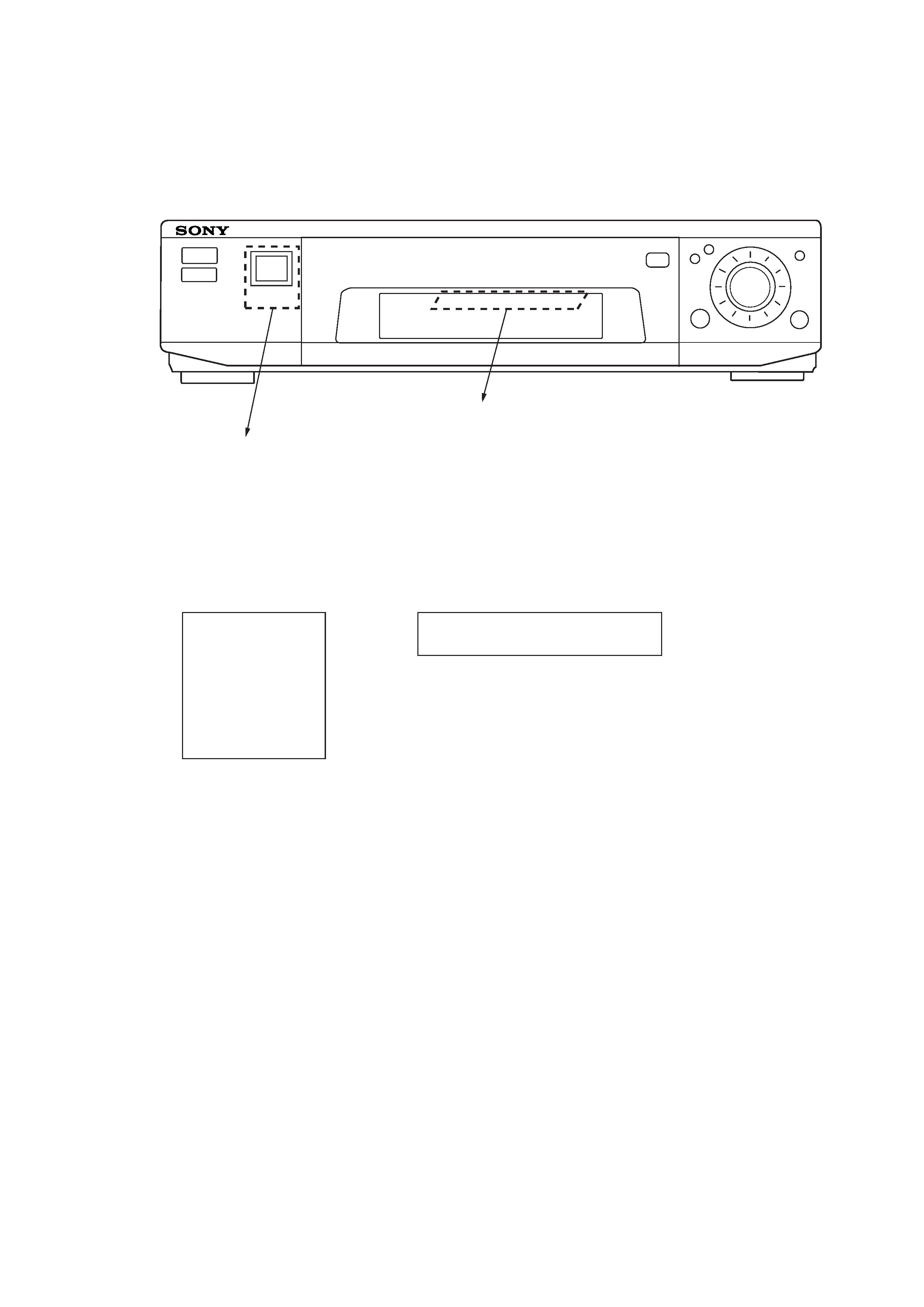
1-1. Antenna Specifications
The two antennas are used. One is large and the other is small. Both the antennas are located inside the front panel of a video cassette
recorder. The large antenna reads the data that is transmitted from the memory chip when a cassette tape is brought closer to the video
cassette recorder. The small antenna reads the data from the memory chip when a cassette tape is inserted to the video cassette recorder.
1. SMART FILE ANTENNA LAYOUT AND FUNCTIONS
Antenna size
Large antenna
(The large antenna reads the data that is
transmitted from the memory chip when a
cassette tape is brought closer to the
video cassette recorder.)
Small antenna
(The small antenna reads the data from the memory chip
when a cassette tape is inserted to the video cassette recorder.)
Fig. 1-1
Small antenna
Large antenna
AT-24 board
AT-23 board
44 x 48 mm
11 x 83 mm
-- 4 --
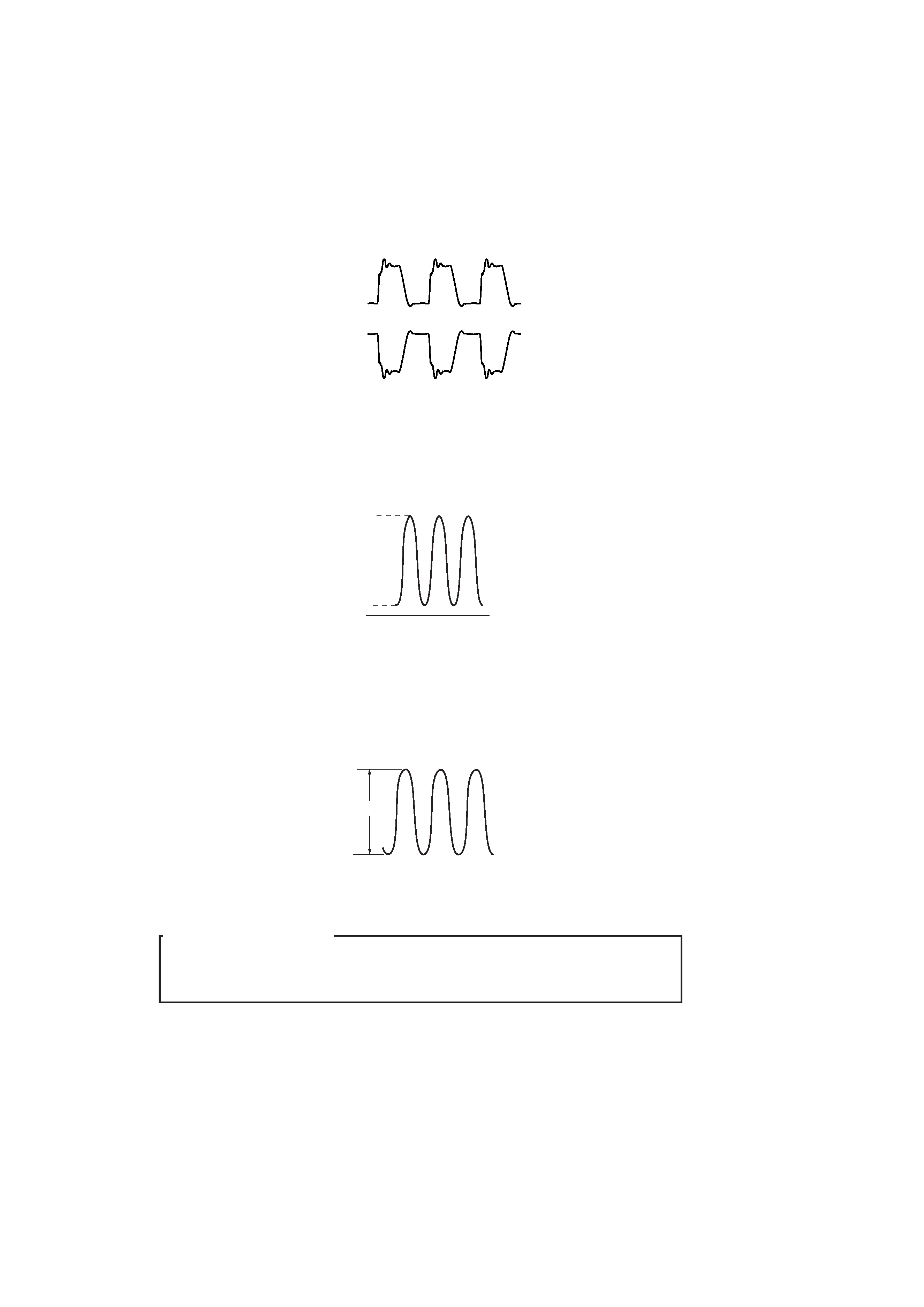
2-1. Transmission Circuit
The operation using the small antenna is described in the parenthesis ( ) below.
· The differential amplifier that consists of Q901 and Q902 (Q911 and Q913), drives the antenna.
· The modulated 13.56 MHz carriers having the opposite polarities each other, are supplied from IC901 pin@£ and pin@¶ (pin@ª and pin#¡)
respectively.
· Q901 (Q911) provides the output signal that swings in the range of 4 V to 20 V at the Q901 (Q911) collector due to L900 (L902).
· Q902 (Q913) provides the output signal that swings in the range of 4 V to 20 V at the Q902 (Q913) collector due to L901 (L903).
· Connect CH-1 of an oscilloscope to CN900 pin3 and CH-2 to CN900 pin2.
· Set CH-2 of an oscilloscope to INV.
· Set MODE of an oscilloscope to ADD.
Measurement method
2. TRANSMISSION
pin@£ (pin#¡)
pin@¶ (pin@ª)
Fig. 2-1
· Amplitude of the output signal is doubled by the differential amplifier so that the output signal having amplitude of 42 V drives the antenna
because the carrier signals having the opposite polarities are supplied to Q901 (Q911) and Q902 (Q913) respectively.
20V
4V
0
Fig. 2-2
Fig. 2-3
32V
-- 5 --
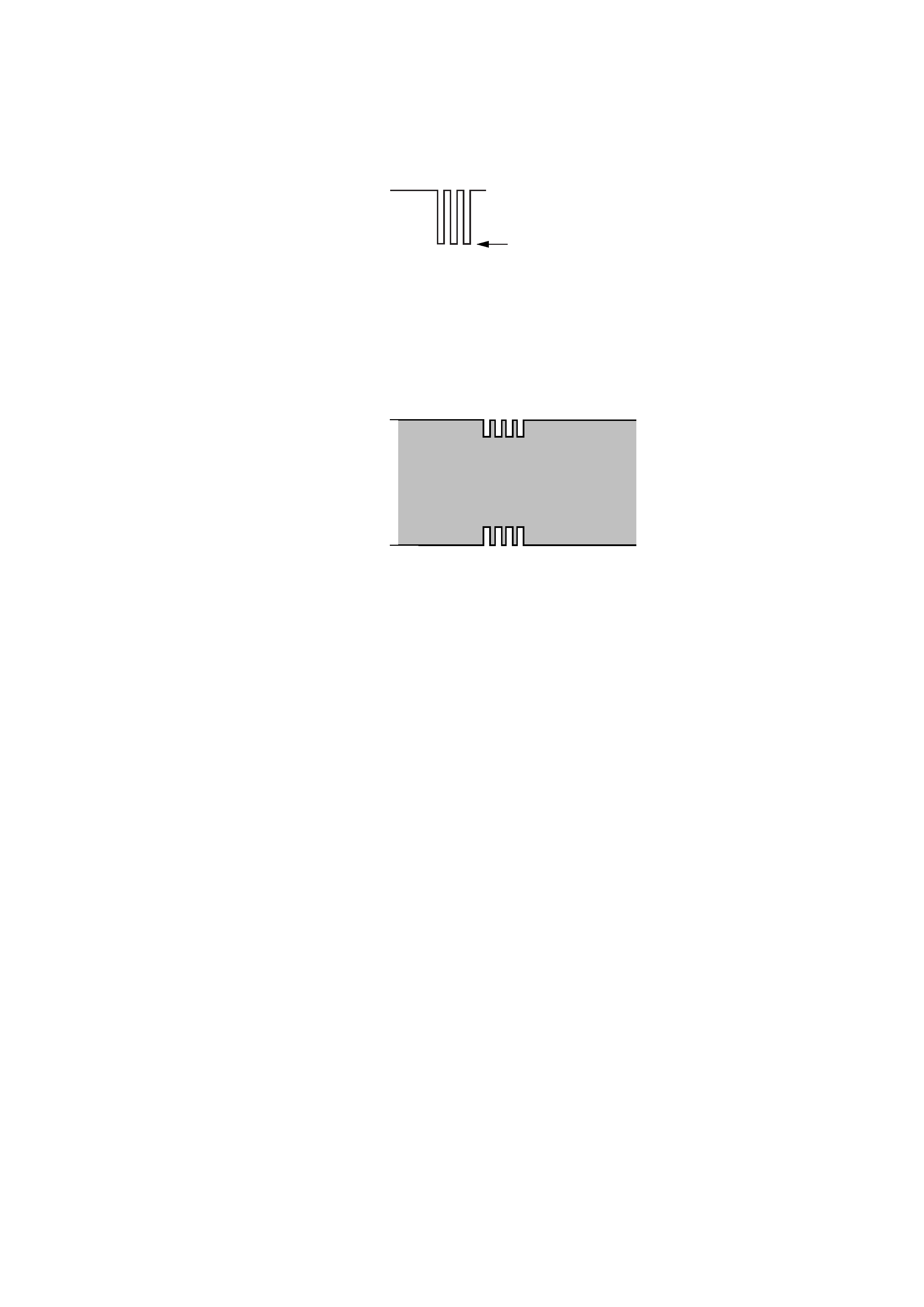
2-2. Modulation Method
Modulation is performed by the signal that is supplied from IC901 pin@¡ (pin#§).
If IC901 pin@¡ (pin#§) goes to "L", the resistor R910 (R941) cannot be connected in parallel so that the current flowing through Q901 and
Q902 (Q911 and Q913) decreases and amplitude of the output signal also decreases.
· Either the large antenna or the small antenna is selected. -- The two antennas do not oscillate at the same time.
IC901
pin@£, pin@¶, pin@¡ to the large antenna
IC901
pin@ª, pin#¡, pin#§ to the small antenna
* The large antenna oscillates normally to read the data from the memory chip when a video cassette is brought closer to the video
cassette recorder.
· The antenna (small) oscillates in the following condition:
* When the TITLE key is pressed in the modes other than Cassette-In/REC END/REC, the system enters the EDIT menu.
* During Title Search/Blank Search
* Cassette IN
Pressing TITLE Another tape is brought closer Pressing TITLE.
pin@¡ (pin#§)
Fig. 2-4
When the modulation signal is present, the
modulation signal goes to the "L" level.
pin3
CN900
Fig. 2-5