SERVICE MANUAL
Taiwan Model
SLV-ED22TW/ED88TW/ED99TW
Korea Model
SLV-ED22KR/ED55KR/ED99KR
Philippines Model
SLV-ED22PL/ED55PL/ED99PL
VIDEO CASSETTE RECORDER
SLV-ED22/ED55/ED88/ED99
RMT-V297/V297A/V297D/V299/V299C
· Refer to the SERVICE MANUAL of VHS MECHANICAL
ADJUSTMENTS VI for MECHANICAL ADJUSTMENTS.
(9-921-647-11)
Photo: SLV-ED99KR
S MECHANISM
* The abbreviations of ED22/ED55/ED88 and ED99 contained in this
service manual are indicated when these models are common to all
their corresponding models as given below.
Abbreviated
ED22
ED55
ED88
ED99
model name
All model
ED22KR
ED55KR
ED99KR
names
ED22PL
ED55PL
ED88TW
ED99PL
SLV-
ED22TW
ED99TW
SPECIFICATIONS
System
Format
VHS NTSC standard
Video recording system
Rotary head helical scanning FM system
Video heads
Double azimuth four heads (SLV-ED55/ED88/
ED99)
Double azimuth two heads (SLV-ED22)
Video signal
NTSC color , EIA standards
Tape speed
SP: 33.35 mm/s (1 3/ 8 inches/s)
EP: 11.11 mm/s ( 7/ 16 inches/s)
LP: 16.67 mm/s ( 11/ 16 inches/s),
playback only
Maximum recording/playback time
8 hrs. in EP mode (with T-160 tape)
Fast-forward and rewind time
Approx. 3 min. (with T-120 tape)
Tuner section
Channel coverage
VHF 2 to 13
UHF 14 to 69
CATV A-8 to A-1, A to W, W+1 to W+84
(SLV-ED22: KR, PL/ED55/ED99: KR, PL)
CATV A-6 to A-1, A, B, C to W+1, W+12 to W+84
(SLV-ED22TW/ED88/ED99TW)
Antenna
75-ohm antenna terminal for VHF/UHF
SLV-ED22: KR, PL/ED55/ED99: KR, PL
SP: 33.35 mm/s (1 3/ 8 inches/s)
EP: 11.11 mm/s ( 7/ 16 inches/s)
SLV-ED22TW/ED88/ED99TW:
Inputs and outputs
SLV-ED99:
LINE-1 IN and LINE-2 IN (SLV-ED99PL)
LINE-1 IN (SAT IN/STB IN), LINE-2 IN and
LINE-3 IN (SLV-ED99: KR, TW)
VIDEO IN, phono jack (1 each)
Input signal: 1 Vp-p, 75 ohms, unbalanced,
sync negative
AUDIO IN, phono jack (2 each)
Input level: 327 mVrms
Input impedance: more than 47 kilohms
Continued on next page

2
SAFETY CHECK-OUT
1. Check the area of your repair for unsoldered or poorly-sol-
dered connections. Check the entire board surface for solder
splashes and bridges.
2. Check the interboard wiring to ensure that no wires are
"pinched" or contact high-wattage resistors.
3. Look for unauthorized replacement parts, particularly transis-
tors, that were installed during a previous repair. Point them
out to the customer and recommend their replacement.
After correcting the original service problem, perform the following
safety checks before releasing the set to the customer:
4. Look for parts which, though functioning, show obvious signs
of deterioration. Point them out to the customer and recom-
mend their replacement.
5. Check the B+ voltage to see it is at the values specified.
SAFETY-RELATED COMPONENT WARNING!!
COMPONENTS IDENTIFIED BY MARK
0 OR DOTTED
LINE WITH MARK
0 ON THE SCHEMATIC DIAGRAMS
AND IN THE PARTS LIST ARE CRITICAL TO SAFE
OPERATION. REPLACE THESE COMPONENTS WITH
SONY PARTS WHOSE PART NUMBERS APPEAR AS
SHOWN IN THIS MANUAL OR IN SUPPLEMENTS PUB-
LISHED BY SONY.
SLV-ED22/ED55:
LINE-1 IN
VIDEO IN, phono jack (1)
Input signal: 1 Vp-p, 75 ohms, unbalanced,
sync negative
AUDIO IN, phono jack (1)
Input level: 327 mVrms
Input impedance: more than 47 kilohms
LINE-2 IN (SLV-ED55)
VIDEO IN, phono jack (1)
Input signal: 1 Vp-p, 75 ohms, unbalanced,
sync negative
AUDIO IN (MONO), phono jack (2)
Input level: 327 mVrms
Input impedance: more than 47 kilohms
LINE-1 OUT
VIDEO OUT, phono jack (1)
Output signal: 1 Vp-p, 75 ohms, unbalanced,
sync negative
AUDIO OUT, phono jack (1)
Standard output: 327 mVrms
Load impedance: 47 kilohms
Output impedance: less than 10 kilohms
Timer section
Clock
Quartz locked
Timer indication
12-hour cycle
Timer setting
8 programs per month (max.)
Power back-up
Built-in self-charging capacitor
Back-up duration: up to 8 hours at a time
General
Power requir ements
110 - 240 V AC, 50/60 Hz
(SLV-ED22PL/ED55PL/ED99PL)
100 V AC, 60 Hz
(SLV-ED22TW/ED88TW/ED99TW)
110 - 220 V AC, 60 Hz
(SLV-ED22KR/ED55KR/ED99KR)
Power consumption
21 W (SLV-ED99KR)
17 W (SLV-ED99PL)
15 W (SLV-ED22: KR, PL/ED55/ED88/ED99TW)
14 W (SLV-ED22TW)
Operating temperature
5
°C to 40°C
Storage temperature
20
°C to 60°C
Dimensions
Approx. 430
× 97 × 288 mm (w/h/d)
including projecting parts and controls
Mass
Approx. 4.1 kg
Supplied accessories
Remote commander (1)
Size AA (R6) batteries (2)
75-ohm coaxial cable with F-type connectors (1)
Plug adaptor (1) (SLV-ED22PL/ED55PL/ED99PL)
Design and specifications are subject to change
without notice.
LINE-2 OUT
AUDIO OUT, phono jack (2)
Standard output: 327 mVrms
Load impedance: 47 kilohms
Output impedance: less than 10 kilohms
SLV-ED88:
LINE-1 IN
VIDEO IN, phono jack (1)
Input signal: 1 Vp-p, 75 ohms, unbalanced,
sync negative
AUDIO IN, phono jack (2 each)
Input level: 327 mVrms
Input impedance: more than 47 kilohms
LINE-1 OUT
VIDEO OUT, phono jack (1)
Output signal: 1 Vp-p, 75 ohms, unbalanced,
sync negative
AUDIO OUT, phono jack (2)
Standard output: 327 mVrms
Load impedance: 47 kilohms
Output impedance: less than 10 kilohms
LINE-2 OUT
AUDIO OUT, phono jack (2)
Standard output: 327 mVrms
Load impedance: 47 kilohms
Output impedance: less than 10 kilohms
LINE-1 OUT
VIDEO OUT, phono jack (1)
Output signal: 1 Vp-p, 75 ohms, unbalanced,
sync negative
AUDIO OUT, phono jack (2)
Standard output: 327 mVrms
Load impedance: 47 kilohms
Output impedance: less than 10 kilohms

3
TABLE OF CONTENTS
Section
Title
Page
Section
Title
Page
SERVICE NOTE ...................................................................... 4
1.
GENERAL
Getting Started .............................................................. 1-1
Basic Operations ........................................................... 1-5
Additional Operations .................................................... 1-8
Editing ............................................................................ 1-12
Additional Information ................................................... 1-13
2.
DISASSEMBLY
2-1.
Upper Case Removal .................................................... 2-1
2-2.
Rear Panel Removal ..................................................... 2-1
2-3.
PSM17-501 Board Removal ......................................... 2-1
2-4.
Front Panel Section Removal ........................................ 2-1
2-5.
Mechanism Deck Removal............................................ 2-2
2-6.
MA-377 Board Removal ................................................ 2-2
2-7.
RF-048 Board Removal (ED22TW/ED88/ED99TW) .... 2-2
2-8.
Internal Views ................................................................ 2-3
2-9.
Circuit Boards Location ................................................. 2-4
3.
BLOCK DIAGRAMS
3-1.
Overall Block Diagram ................................................... 3-1
3-2.
Video Block Diagram ..................................................... 3-3
3-3.
Servo/System Control Block Diagram .......................... 3-5
3-4.
Audio Block Diagram ..................................................... 3-7
3-5.
Tuner Block Diagram ..................................................... 3-9
3-6.
Mode Control Block Diagram ........................................ 3-11
3-7.
Power Block Diagram .................................................... 3-13
4.
PRINTED WIRING BOARDS AND
SCHEMATIC DIAGRAMS
4-1.
Frame Schematic Diagram ............................................ 4-3
4-2.
Printed Wiring Boards and Schematic Diagrams ......... 4-5
MA-377 Printed Wiring Board ....................................... 4-5
MA-377 (Video, Audio) Schematic Diagram ................. 4-9
MA-377 (System Control) Schematic Diagram ............ 4-13
MA-377 (Servo Control) Schematic Diagram ............... 4-15
MA-377 (Hi-Fi Audio) Schematic Diagram .................... 4-17
MA-377 (Tuner) Schematic Diagram ............................ 4-19
MA-377 (I/O) Schematic Diagram ................................. 4-21
MA-377 (Mode Control) Schematic Diagram ................ 4-23
GK-12 Printed Wiring Board and
Schematic Diagram ....................................................... 4-25
RF-048 Printed Wiring Board and
Schematic Diagram ....................................................... 4-27
FJ-26, MF-321 Printed Wiring Boards and
Schematic Diagrams ..................................................... 4-29
DS-92, KK-24 Printed Wiring Boards and
Schematic Diagrams ..................................................... 4-31
PSM17-501 Printed Wiring Board ................................. 4-33
PSM17-501 Schematic Diagram ................................... 4-35
5.
INTERFACE, IC PIN FUNCTION DESCRIPTION
5-1.
System Control-Video Block Interface
(MA-377 BOARD IC101) ............................................... 5-1
5-2.
System Control-Servo Peripheral Circuit Interface
(MA-377 BOARD IC101) ............................................... 5-1
5-3.
System Control-Mechanism Block Interface
(MA-377 BOARD IC101) ............................................... 5-2
5-4.
System Control-Audio Block Interface
(MA-377 BOARD IC101) ............................................... 5-3
5-5.
Servo/System Control,
OSD Microprocessor Pin Function
(MA-377 BOARD IC101) ............................................... 5-4
5-6.
ZWEITON Processor Pin Function
(GK-12 BOARD IC001) ................................................. 5-5
6.
ERROR CODES ....................................................... 6-1
7.
ADJUSTMENTS
7-1.
Mechanical Adjustments ............................................... 7-1
7-2.
Electrical Adjustments ................................................... 7-1
2-1.
Pre-Adjustment Preparations ........................................ 7-1
2-1-1. Instruments to be Used ............................................ 7-1
2-1-2. Connection ............................................................... 7-1
2-1-3. Set-up of Adjustment ............................................... 7-1
2-1-4. Alignment Tapes ....................................................... 7-1
2-1-5. Specified I/O Level and Impedance
Input/Output terminal ............................................... 7-1
2-1-6. Adjusting Sequence ................................................. 7-2
2-2.
Power Supply Adjustment ............................................. 7-2
2-2-1. Power Supply Check ................................................ 7-2
2-3.
Servo System Adjustment ............................................. 7-2
2-3-1. RF Switching Position Adjustment ........................... 7-2
2-4.
Audio System Adjustments ........................................... 7-3
2-4-1. Hi-Fi Audio System Adjustment ............................... 7-3
1.
AF Switching Position Adjustment ........................... 7-3
2.
Frequency Response Check .................................... 7-3
3.
Overall Level Characteristic and
Distortion Factor Check ........................................... 7-4
4.
Overall S/N Check .................................................... 7-4
2-4-2. Normal Audio System Adjustment ........................... 7-4
1.
ACE Head Adjustment ............................................. 7-4
2.
E-E Output Level Check ........................................... 7-4
3.
Frequency Response Check .................................... 7-4
4.
Overall Level Characteristic and Distortion
Factor Check ............................................................ 7-5
5.
Overall S/N Check .................................................... 7-5
2-5.
Tuner System Adjustment ............................................. 7-5
2-5-1. Separation Adjustment ............................................. 7-5
2-6.
Par ts Arrangement Diagram for Adjustments ............... 7-6
8.
REPAIR PARTS LIST
8-1.
Exploded Views ............................................................. 8-1
8-1-1. Front Panel and Cabinet Assemblies ....................... 8-1
8-1-2. Chassis Assembly .................................................... 8-2
8-1-3. Mechanism Chassis Assembly (1) ........................... 8-3
8-1-4. Mechanism Chassis Assembly (2) ........................... 8-4
8-1-5. Mechanism Chassis Assembly (3) ........................... 8-5
8-2.
Electrical Parts List ....................................................... 8-6
4
SERVICE NOTE
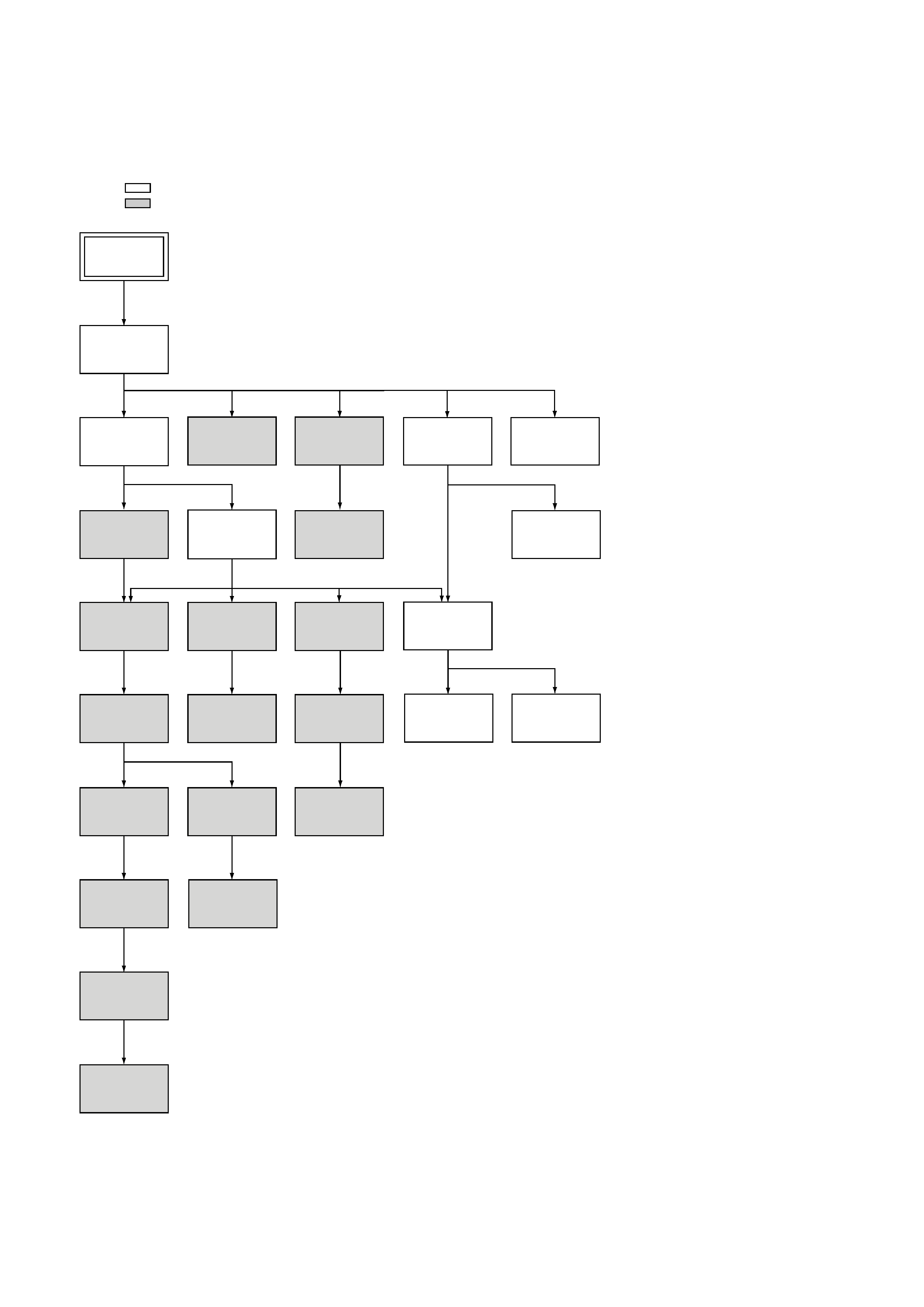
1. DISASSEMBLY
· This set can be disassembled in the order shown below.
Note: Pages in
indicated pages in the SERVICE MANUAL.
Pages in
indicated pages in the VHS MECHANICAL ADJUSTMENT MANUAL VI.
Set
Upper case
(Page 2-1)
Front Panel
Section
(Page 2-1)
PSM17-501
Board
(Page 2-1)
Pinch Press
Block Ass'y
(Page 14)
Ground Shaft
Ass'y
(Page 13)
Mechanism
Deck
(Page 2-2)
FL Complete
Ass'y
(Page 13)
Drum
Ass'y
(Page 13)
Rear
Panel
(Page 2-1)
RF-048
Board
(Page 2-2)
Rubber
Belt
(Page 15)
Rubber
Belt
(Page 15)
Slider
(Page 26)
Loading
Gear (T, S)
(Page 28)
Retainer
Plate
(Page 22)
Rubber
Belt
(Page 15)
Capstan
Motor
(Page 15)
FL Slider
Block Ass'y
(Page 22)
Pully Gear
Ass'y
(Page 29)
Cam Motor
Retainer
(Page 31)
Cam Gear
(Page 23)
Cam Motor
(Page 31)
Reel Direct
Ass'y
(Page 30)
MA-377
Board
(Page 2-2)
Rotary
Switch
(Page 2-2)
Tuner
Unit
1-1
SECTION 1
GENERAL
This section is extracted from SLV-
ED22KR/ED55KR/ED99KR instruction
manual. (3-058-932-11)
SLV-ED22/ED55/ED88/ED99
Getting Started
4
Getting Started
Step 1
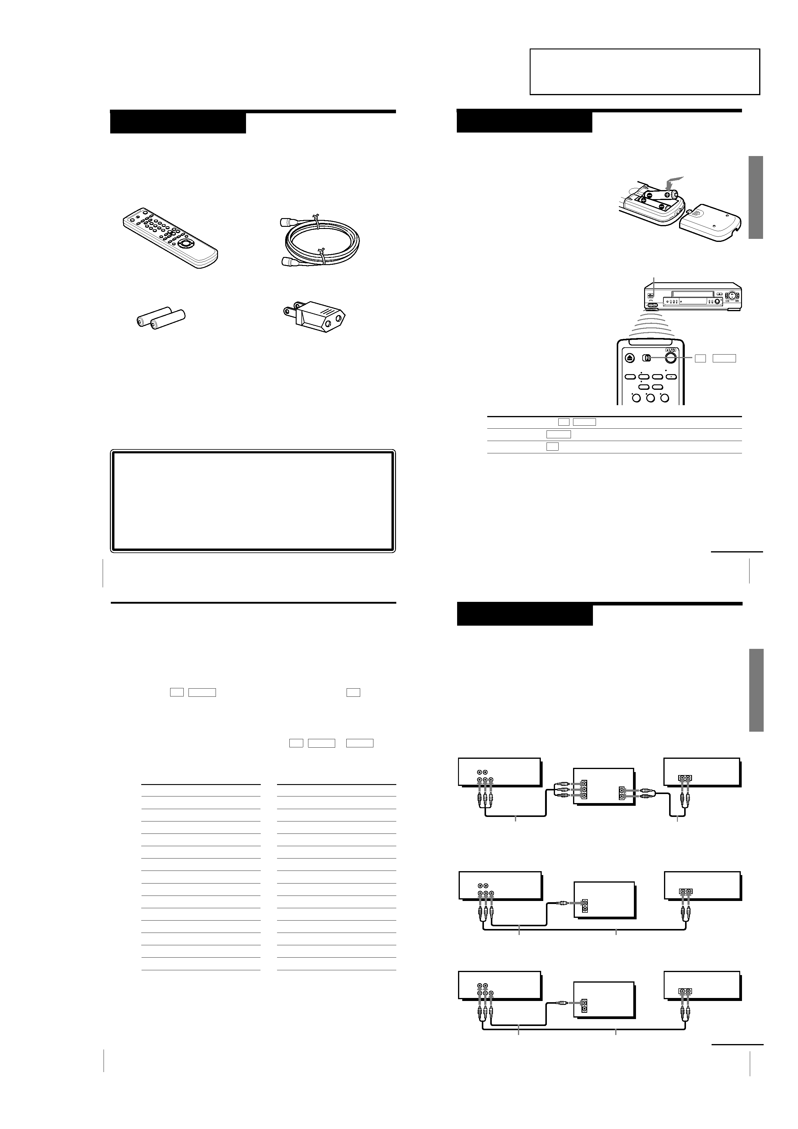
Unpacking
Check that you have received the following items with the VCR:
· Remote commander
· Size AA (R6) batteries
· 75-ohm coaxial cable with F-type
connectors
· Plug adaptor
Checking your model name
The instructions in this manual are for the 3 models: SLV-ED99PL,
ED55PL and ED22PL. Check your model number by looking at the
rear panel of your VCR. SLV-ED99PL is the model used for illustration
purpose. Any difference in operation is clearly indicated in the text,
for example,"SLV-ED22PL only."
5
Getting Started
Getting
Started
Inserting the batteries
Insert two size AA (R6) batteries by
matching the + and on the batteries
to the diagram inside the battery
compartment.
Insert the negative () end first, then
push in and down until the positive
(+) end clicks into position.
Using the remote commander
You can use this remote
commander to operate this VCR
and a Sony TV. Buttons on the
remote commander marked with
a dot (·) can be used to operate
your Sony TV. If the TV does not
have the g symbol near the
remote sensor, this remote
commander will not operate the
TV.
Step 2
Setting up the remote commander
To operate
the VCR
a Sony TV
Set TV / VIDEO to
VIDEO and point at the remote sensor on the VCR
TV and point at the remote sensor on the TV
Remote sensor
TV
/
VIDEO
Notes
· With normal use, the batteries should last about three to six months.
· If you do not use the remote commander for an extended period of time, remove
the batteries to avoid possible damage from battery leakage.
· Do not use a new battery with an old one.
· Do not use different types of batteries.
123
continued
Getting Started
6
Controlling other TVs with the remote commander
(SLV-ED99PL only)
The remote commander is preprogrammed to control non-Sony TVs. If your
TV is listed in the table below, set the appropriate manufacturer's code
number.
1 Set TV / VIDEO at the top of the remote commander to TV .
2 Hold ?/1 down, and enter your TV's code number(s) using the number
buttons. Then release
?/1.
Now you can use the
?/1, VOL +/, CH +/ and TV/VIDEO buttons to
control your TV. You can also use the buttons marked with a dot (
·) to
control a Sony TV. To control the VCR, reset TV / VIDEO to VIDEO .
Code numbers of controllable TVs
If more than one code number is listed, try entering them one at a time until
you find the one that works with your TV.
Step 2: Setting up the remote commander (continued)
Notes
· If the TV uses a different remote control system from the one programmed to work
with the VCR, you cannot control your TV with the remote commander.
· You may not be able to use some buttons to control non-Sony TVs due to the remote
commander's signal limitations.
· If you enter a new code number, the code number previously entered will be erased.
· When you replace the batteries of the remote commander, the code number may
automatically reset to 01 (Sony). If your TV is not a Sony, it is recommended to
manually set the appropriate code number every time you replace the batteries.
Manufacturer
Sony
Akai
AOC
Centurion
Colonad
Curis-Mathes
Emerson
Fisher
General Electric
Gold Star
Hitachi
JVC
Magnavoc
Marantz
Code number
01
04
04
12
03
12
03, 04, 14
11
06, 10
03, 04, 17
02
09
08
13
Manufacturer
MGA/Mitsubishi
Panasonic
Philips
Pioneer
Quasar
Radio Shack
RCA
Sanyo
Sears
Sharp
Sylvania
Teknika
Toshiba
Zenith
Code number
13
06, 19
08
16
06
05, 14
10
11
07, 11
05, 18
08
14
07
15
7
Getting Started
Getting
Started
Step 3
Hookup
Audio/video (A/V) hookup
If your TV has audio/video (A/V) input jacks, you will get a better picture
and sound when you hook up your VCR using these connections. If your TV
doesn't have A/V inputs, see the following page for antenna hookup.
For SLV-ED99PL only
For a true "home theater" experience, you should connect the audio outputs
of your VCR or TV to your stereo system.
A Use this hookup if your TV has stereo jacks
B Use this hookup if your TV doesn't have stereo jacks
VCR
Stereo receiver
Audio/video cable (not supplied)
TV
TV
VCR
Stereo receiver
Video cable (not supplied)
Audio cable (not supplied)
Audio cable (not supplied)
IN
VIDEO
AUDIO
AUDIO OUT
AUX IN
AUDIO VIDEO
LINE-2
OUT
LINE-1
OUT
VIDEO
AUDIO
IN
AUX IN
AUDIO VIDEO
LINE-2
OUT
LINE-1
OUT
TV
VCR
Stereo receiver
Video cable (not supplied)
Audio cable (not supplied)
VIDEO
AUDIO
IN
AUX IN
AUDIO VIDEO
LINE-2
OUT
LINE-1
OUT
or
continued