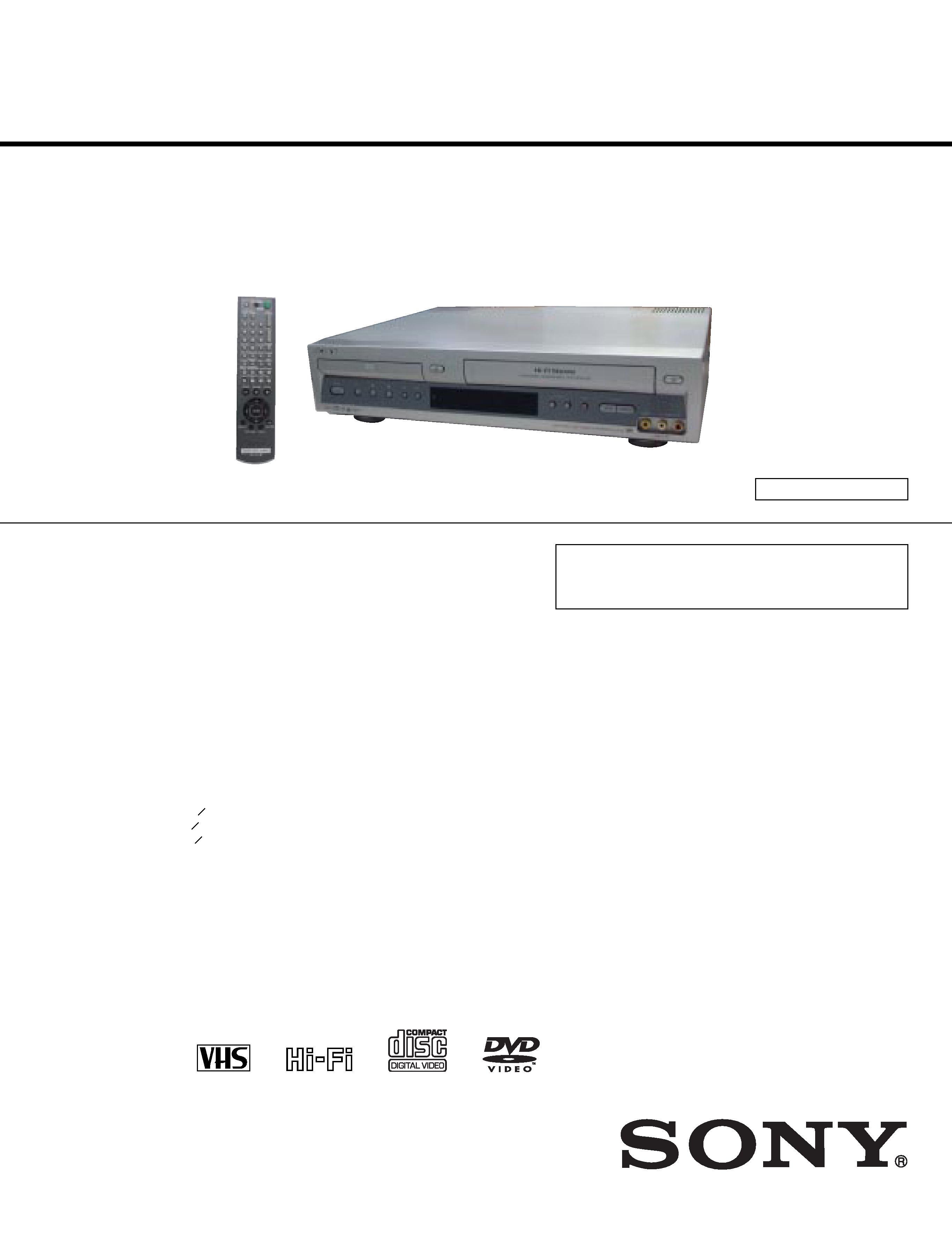
US Model
Canadian Model
SERVICE MANUAL
DVD PLAYER/
VIDEO CASSETTE RECORDER
Refer to the SERVICE MANUAL of VHS MECHANI-
CAL ADJUSTMENT MANUAL VII for MECHANICAL
ADJUSTMENTS. (9-921-790-11)
SPECIFICATIONS
SLV-D100
RMT-V501
System
Laser
Semiconductor laser
Format
VHS NTSC standard
Video recording system
Rotary head helical scanning FM system
Video heads
Double azimuth four heads
Video signal
NTSC color, EIA standards
Tape speed
SP: 33.35 mm/s (1
inches/s)
EP: 11.12 mm/s (
inches/s)
LP: 16.67 mm/s (
inches/s),
playback only
Maximum recording/playback time
8 hrs. in EP mode (with T-160 tape)
Rewind time
Approx. 1 min (with T-120 tape)
Tuner section
Channel coverage
VHF 2 to 13
UHF 14 to 69
CATV A-8 to A-1, A to W, W+1 to W+84
Antenna
75-ohm antenna terminal for VHF/UHF
Audio characteristics
Frequency response
DVD VIDEO (PCM 96 kHz): 2 Hz to 44 kHz (
±1.0
dB)/DVD VIDEO (PCM 48 kHz): 2 Hz to 22 kHz
(
±0.5 dB)/CD: 2 Hz to 20 kHz (±0.5 dB)
Signal-to-noise ratio (S/N ratio)
115 dB (LINE OUT (L/R) AUDIO jacks only)
Harmonic distortion
0.003 %
Dynamic range
DVD VIDEO: 103 dB/CD: 99 dB
Wow and flutter
Less than detected value (
±0.001% W PEAK)
The signals from LINE OUT L/R (AUDIO) jacks are
measured. When you play PCM sound tracks with a 96
kHz sampling frequency, the output signals from the
DIGITAL OUT (OPTICAL or COAXIAL) jack are
converted to 48 kHz sampling frequency.
Inputs and outputs
LINE IN 1 and LINE-2 IN
VIDEO IN, phono jack (1 each)
Input signal: 1 Vp-p, 75 ohms, unbalanced, sync
negative
AUDIO IN, phono jacks (2 each)
Input level: 327 mVrms
Input impedance: more than 47 kilohms
LINE OUT
VIDEO OUT, phono jack (1)
Output signal: 1 Vp-p, 75 ohms, unbalanced,
sync negative
AUDIO OUT, phono jacks (2)
Standard output: 327 mVrms
Load impedance: 47 kilohms
Output impedance: less than 10 kilohms
DIGITAL OUT
OPTICAL, Optical output jack
18 dBm (wave length: 660 nm)
COAXIAL, phono jack
Output signal: 0.5 Vp-p, 75 ohms
COMPONENT VIDEO OUT (Y, Pb, Pr)
Phono jack
Y: 1.0 Vp-p/Pb, Pr: 0.7 Vp-p, 75 ohms
Timer section
Clock
Quartz locked
Timer indication
12-hour cycle
Timer setting
8 programs (max.)
3
8
7
16
11
16
General
Power requirements
120 V AC, 60 Hz
Power consumption
29 W
Operating temperature
0
°C to 45°C (32°F to 113°F)
Storage temperature
20
°C to 60°C ( 4°F to 140°F)
Operating humidity
25% to 80%
Dimensions including projecting parts and controls
(w/h/d)
Approx. 430
× 100 × 330 mm
(Approx. 17
× 4 × 13 inches)
Mass
Approx. 4.5 kg (Approx. 9.9 lbs)
Supplied accessories
Remote commander (1)
Size AA (R6) batteries (2)
75-ohm coaxial cable with F-type connectors (1)
Audio/video cord (pinplug
× 3 ypinplug × 3) (1)
Design and specifications are subject to change
without notice.
TS-10 MECHANISM
-- 2 --
WARNING!!
WHEN SERVICING, DO NOT APPROACH THE LASER
EXIT WITH THE EYE TOO CLOSELY. IN CASE IT IS
NECESSARY TO CONFIRM LASER BEAM EMISSION,
BE SURE TO OBSERVE FROM A DISTANCE OF
MORE THAN 25 cm FROM THE SURFACE OF THE
OBJECTIVE LENS ON THE OPTICAL PICK-UP BLOCK.
CAUTION
Use of controls or adjustments or performance of procedures
other than those specified herein may result in hazardous
radiation exposure.
ATTENTION AU COMPOSANT AYANT RAPPORT
À LA SÉCURITÉ!
LES COMPOSANTS IDENTIFIÉS PAR UNE MARQUE 0
SUR LES DIAGRAMMES SCHÉMATIQUES ET LA LISTE
DES PIÈCES SONT CRITIQUES POUR LA SÉCURITÉ
DE FONCTIONNEMENT. NE REMPLACER CES COM-
POSANTS QUE PAR DES PIÈCES SONY DONT LES
NUMÉROS SONT DONNÉS DANS CE MANUEL OU DANS
LES SUPPLÉMENTS PUBLIÉS PAR SONY.
SAFETY-RELATED COMPONENT WARNING!!
COMPONENTS IDENTIFIED BY MARK 0 OR DOTTED
LINE WITH MARK 0 ON THE SCHEMATIC DIAGRAMS
AND IN THE PARTS LIST ARE CRITICAL TO SAFE
OPERATION. REPLACE THESE COMPONENTS WITH
SONY PARTS WHOSE PART NUMBERS APPEAR AS
SHOWN IN THIS MANUAL OR IN SUPPLEMENTS
PUBLISHED BY SONY.
CAUTION:
The use of optical instrument with this product will increase eye
hazard.
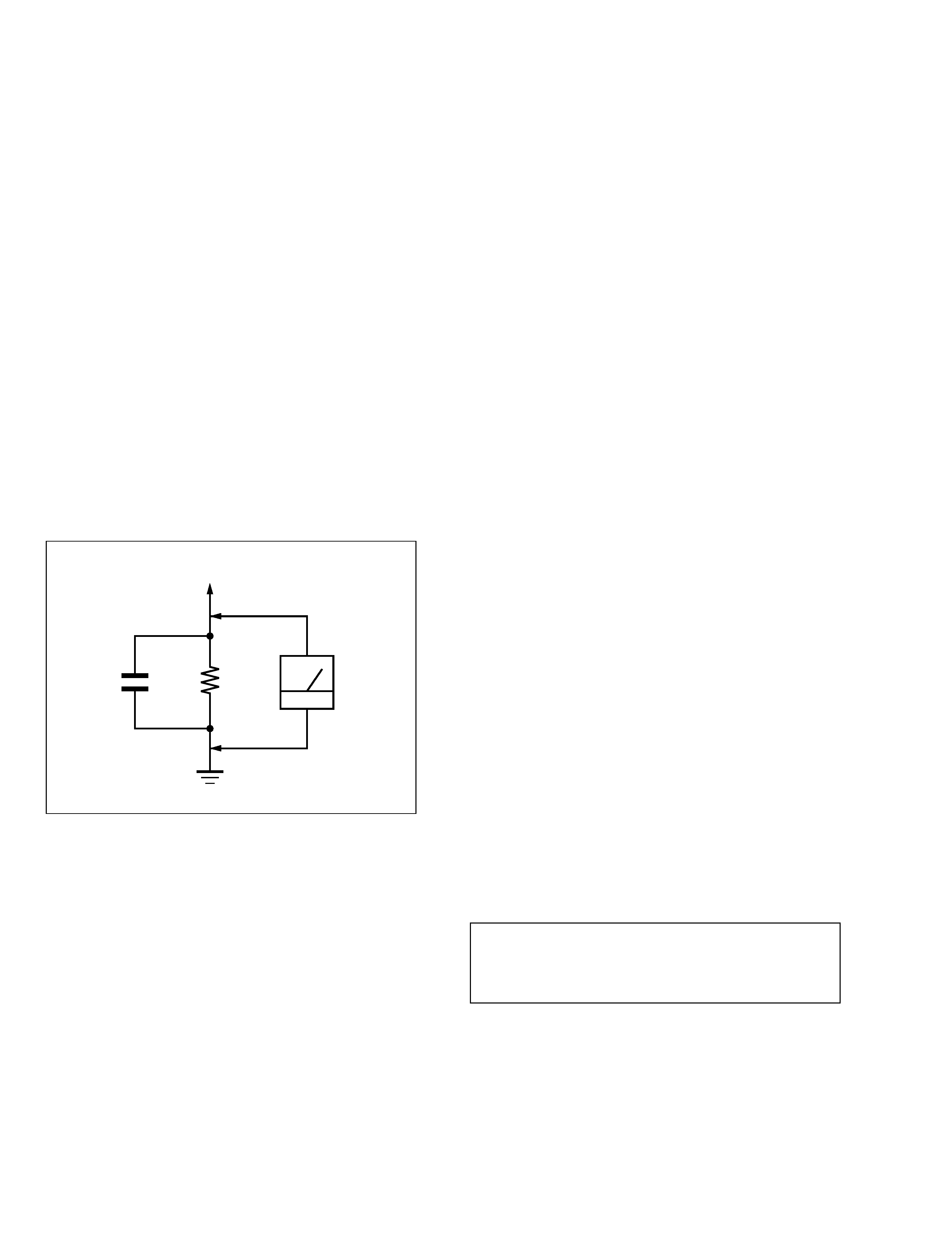
Fig. A.
Using an AC voltmeter to check AC leakage.
1.5 k
0.15 µF
AC
voltmeter
(0.75 V)
To Exposed Metal
Parts on Set
Earth Ground
LEAKAGE TEST
The AC leakage from any exposed metal part to earth ground
and from all exposed metal parts to any exposed metal part having
a return to chassis, must not exceed 0.5 mA (500 microamperes).
Leakage current can be measured by any one of three methods.
1. A commercial leakage tester, such as the Simpson 229 or RCA
WT-540A. Follow the manufacturers' instructions to use these
instruments.
2. A battery-operated AC milliammeter. The Data Precision 245
digital multimeter is suitable for this job.
3. Measuring the voltage drop across a resistor by means of a VOM
or battery-operated AC voltmeter. The "limit" indication is
0.75V, so analog meters must have an accurate low-voltage scale.
The Simpson 250 and Sanwa SH-63Trd are examples of a
passive VOM that is suitable. Nearly all battery operated digital
multimeters that have a 2V AC range are suitable. (See Fig. A)
1. Check the area of your repair for unsoldered or poorly-soldered
connections. Check the entire board surface for solder splashes
and bridges.
2. Check the interboard wiring to ensure that no wires are "pinched"
or contact high-wattage resistors.
3. Look for unauthorized replacement parts, particularly transistors,
that were installed during a previous repair. Point them out to the
customer and recommend their replacement.
4. Look for parts which, though functioning, show obvious signs of
deterioration. Point them out to the customer and recommend
their replacement.
5. Check the line cord for cracks and abrasion. Recommend the
replacement of any such line cord to the customer.
6. Check the B+ voltage to see it is at the values specified.
7. Check the antenna terminals, metal trim, "metallized" knobs,
screws, and all other exposed metal parts for AC leakage. Check
leakage as described below.
SAFETY CHECK-OUT
After correcting the original service problem, perform the following
safety checks before releasing the set to the customer:

-- 3 --
TABLE OF CONTENTS
Precaution
1
Safety Precautions ·································································· 4
2
Handling the Optical Pick-up ················································ 6
3
Pick-up Disassembly and Reassembly ·································· 7
1.
General
Getting Started ···································································· 1-1
Basic Operations ································································· 1-6
Advanced Hookups ···························································· 1-9
DVD Settings and Adjustements ······································ 1-10
DVD Additional Operations ············································· 1-13
VCR Additional Operations ············································· 1-18
Additional Infomation ······················································ 1-20
2.
Disassembly and Reassembly
2-1
Cabinet and PCB
2-1-1 Cabinet Top Removal ························································· 2-1
2-1-2 Bottom Cover Removal ······················································ 2-1
2-1-3 Ass'y Front Panel Removal ················································ 2-1
2-1-4 Function-Timer PCB Removal ··········································· 2-1
2-1-5 Chassis Removal ································································ 2-2
2-1-6 VCR Main PCB Removal ·················································· 2-2
2-2
DVD Deck
2-2-1 Tray Disc Removal ····························································· 2-3
2-2-2 Ass'y P/U Deck Removal ··················································· 2-4
2-2-3 Housing Ass'y Removal ····················································· 2-5
2-2-4 Sub Chassis Removal ························································· 2-6
2-2-5 Ass'y Brkt Deck Removal ·················································· 2-7
2-3
Circuit Board Locations ····················································· 2-8
3.
Block Diagram
4.
PCB Diagrams
4-1
VCR Main ·········································································· 4-3
4-2
DVD Main ·········································································· 4-7
4-3
Function-Timer ··································································· 4-9
5.
Schematic Diagrams
Block Identification of Main PCB ············································ 5-3
5-1
S.M.P.S. ·············································································· 5-5
5-2
Power Drive ········································································ 5-7
5-3
Function-Timer ··································································· 5-9
5-4
Logic ················································································· 5-11
5-5
A/V ··················································································· 5-13
5-6
Hi-Fi/MTS ········································································ 5-15
5-7
Input-Output ····································································· 5-17
5-8
DVD Main-Micom/AV Decoder ······································ 5-19
5-9
DVD Servo ······································································· 5-21
5-10 DVD Audio/Video ···························································· 5-23
6.
VCR Alignment and Adjustments
6-1
Reference ············································································ 6-1
6-1-1 Location of Adjustment Button of Remote Control ··········· 6-1
6-1-2 TEST Location for Adjustment Mode Setting ··················· 6-2
6-2
Mechanical Adjustment ······················································ 6-3
6-2-1 The Number and Position of Test Point ····························· 6-3
6-2-2 ACE Head Position (X-Point) Adjustment ························· 6-3
6-3
Head Switching Point Adjustment ····································· 6-4
7.
Troubleshooting ···················································· 7-1
8.
Repair Parts List
8-1
Exploded Views ·································································· 8-2
8-1-1 Cabinet Assembly ······························································· 8-2
8-1-2 VCR Mechanical Parts (Top Side) ····································· 8-3
8-1-3 VCR Mechanical Parts (Bottom Side) ······························· 8-4
8-1-4 DVD Mechanical Parts ······················································· 8-5
8-2
Electrical Parts List ···························································· 8-6
-- 4 --
Precautions
1 Safety Precautions
1. Be sure that all of the built-in protective devices are
replaced. Restore any missing protective shields.
2. When reinstalling the chassis and its assemblies, be sure
to restore all pretective devices, including : control knobs
and compartment covers.
3. Make sure that there are no cabinet openings through
which people--particularly children--might insert fingers
and contact dangerous voltages. Such openings include
the spacing between the picture tube and the cabinet
mask, excessively wide cabinet ventilation slots, and
improperly fitted back covers.
If the measured resistance is less than 1.0 megohm or
greater than 5.2 megohms, an abnormality exists that
must be corrected before the unit is returned to the
customer.
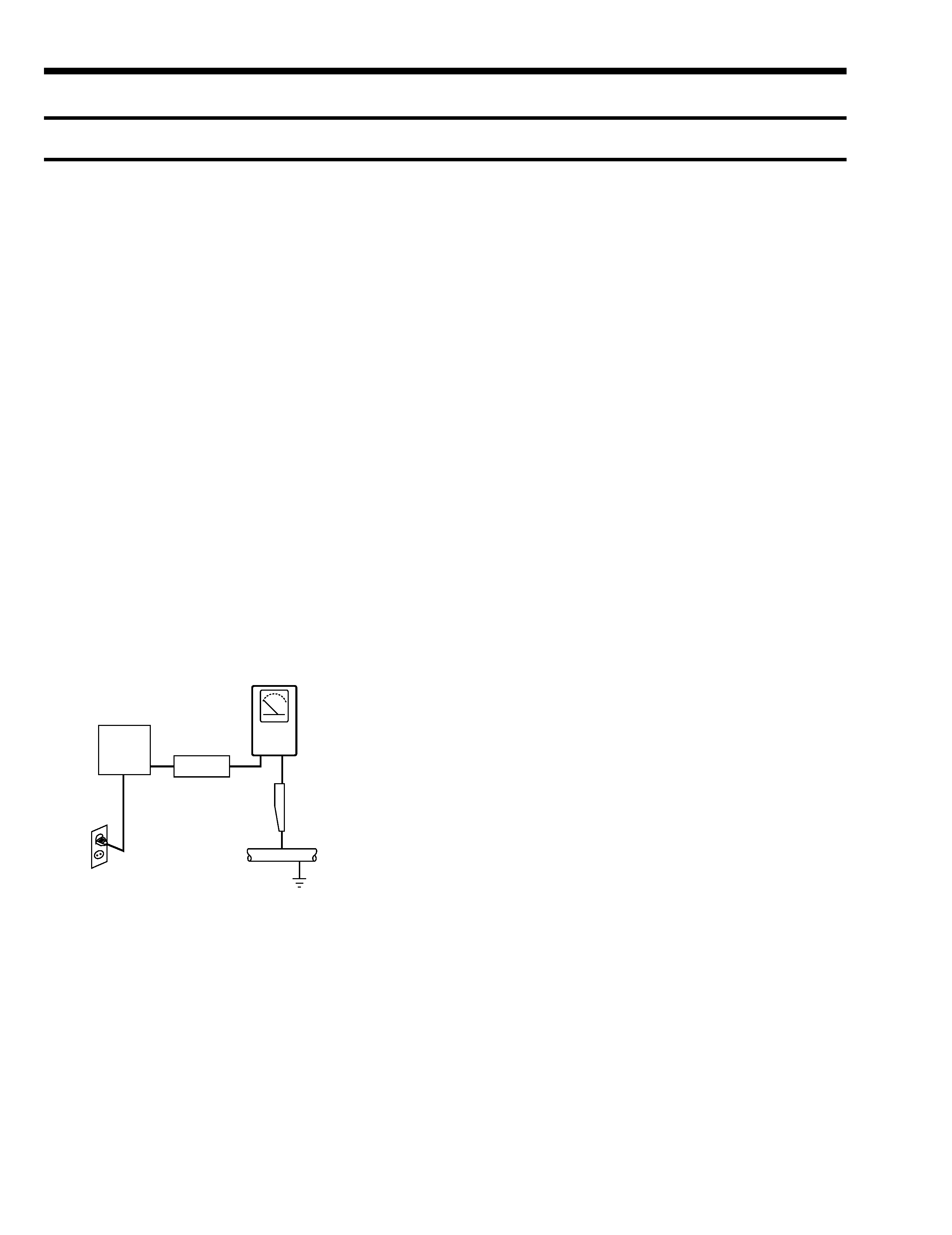
4. Leakage Current Hot Check (See Fig. 1-1) :
Warning : Do not use an isolation transformer during this
test. Use a leakage current tester or a metering system
that complies with American National Standards Institute
(ANSI C101.1, Leakage Current for Appliances), and
Underwriters Laboratories (UL Publication UL1410,
59.7).
5. With the unit completely reassembled, plug the AC line
cord directly the power outlet. With the unit's AC switch
first in the ON position and then OFF, measure the
current between a known erath ground (metal water pipe,
conduit, etc.) and all exposed metal parts, including :
antennas, handle brackets, metal cabinets, screwheads
and control shafts. The current measured should not
exceed 0.5 milliamp. Reverse the power-plug prongs in
the AC outlet and repeat the test.
6. Antenna Cold Check :
With the unit's AC plug disconnected from the AC
source, connect an electrical jumper across the two AC
prongs. Connect one lead of the ohmmeter to an AC
prong.
Connect the other lead to the coaxial connector.
7. Some semiconductor ("solid state") devices are easily
damaged by static electricity.
Such components are called Electrostatically Sensitive
Devices (ESDs); examples include integrated circuits and
some field-effect transistors. The following techniques
will reduce the occurrence of component damage caused
by static electricity.
8. Immediately before handling sny semiconductor
components or assemblies, drain the electrostatic charge
from your body by touching a known earth ground.
Alternatively, wear a discharging Wrist-strap device. (Be
sure to remove it prior to applying power--this is an
electric shock precaution.)
9. Design Alteration Warning :
Never alter or add to the mechanical or electrical design
of this unit. Example : Do not add auxiliary audio or
video connectors.
Such alterations might create a safety hazard.
Also, any design changes or additions will void the
manufacturer's warranty.
10. Never defeat any of the B+ voltage interlocks.
Do not apply AC power to the unit (or any of its
assemblies) unless all solid-state heat sinks are correctly
installed.
11. Always connect a test instrument's ground lead to the
instrument chassis ground before connecting the positive
lead; always remove the instrument's ground lead last.
Fig1. AC Leakage Test
DEVICE
UNDER
TEST
(READING SHOULD
NOT BE ABOVE
0.5mA)
LEAKAGE
CURRENT
TESTER
EARTH
GROUND
TEST ALL
EXPOSED METER
SURFACES
ALSO TEST WITH
PLUG REVERSED
(USING AC ADAPTER
PLUG AS REQUIRED)
2-WIRE CORD

-- 5 --
12. Observe the original lead dress, especially near the
following areas : Antenna wiring, sharp
edges, and especially the AC and high voltage power
supplies. Always inspect for pinched, out-of-place, or
frayed wiring. Do not change the spacing between
components and the printed circuit board. Check the AC
power cord for damage. Make sure that leads and
components do not touch thermally hot parts.
13. Product Safety Notice :
Some electrical and mechanical parts have special safety-
related characteristics which might not be obvious from
visual inspection. These safety features and the protection
they give might be lost if the replacement component
differs from the original--even if the replacement is rated
for higher voltage, wattage, etc.
Components that are critical for safety are indicated in the
circuit diagram by shading, (
or
).
Use replacement components that have the same ratings,
especially for flame resistance and dielectric strength
specifications. A replacement part that does not have the
same safety characteristics as the original might create
shock, fire or other hazards.