SPECIAL-EFFECTS
GENERATOR
SEG-1
2V990769-1
373-Printing
SONY CORPORATION OF AMERICA
4747 Van Dam Stnet, Long
Island City, New York 11101
PRINTED IN USA

TABLE OF CONTENTS
General
Description
. . . . . . . . . . . . . . . . . . . . . . . . . . . . .
1
Circuit Description .............................1
Transistor Voltage Chart. ..........................3
Illustrations
...............................4
Test Points and Waveforms, Signal Processing Board. ..........
4
Test Points and Waveforms, Sync Generator Board ............
5
Schematic Diagram, Signal Processing Board ..............
6
Printed Circuit, Signal Processing Board ................
7
Schematic Diagram, Sync Generator Board
...............
8
Printed Circuit, Sync Generator Board .................. 9
Parts List
...............................
10
Supplement ................................13
GENERAL DESCRIPTION
INTRODUCTION
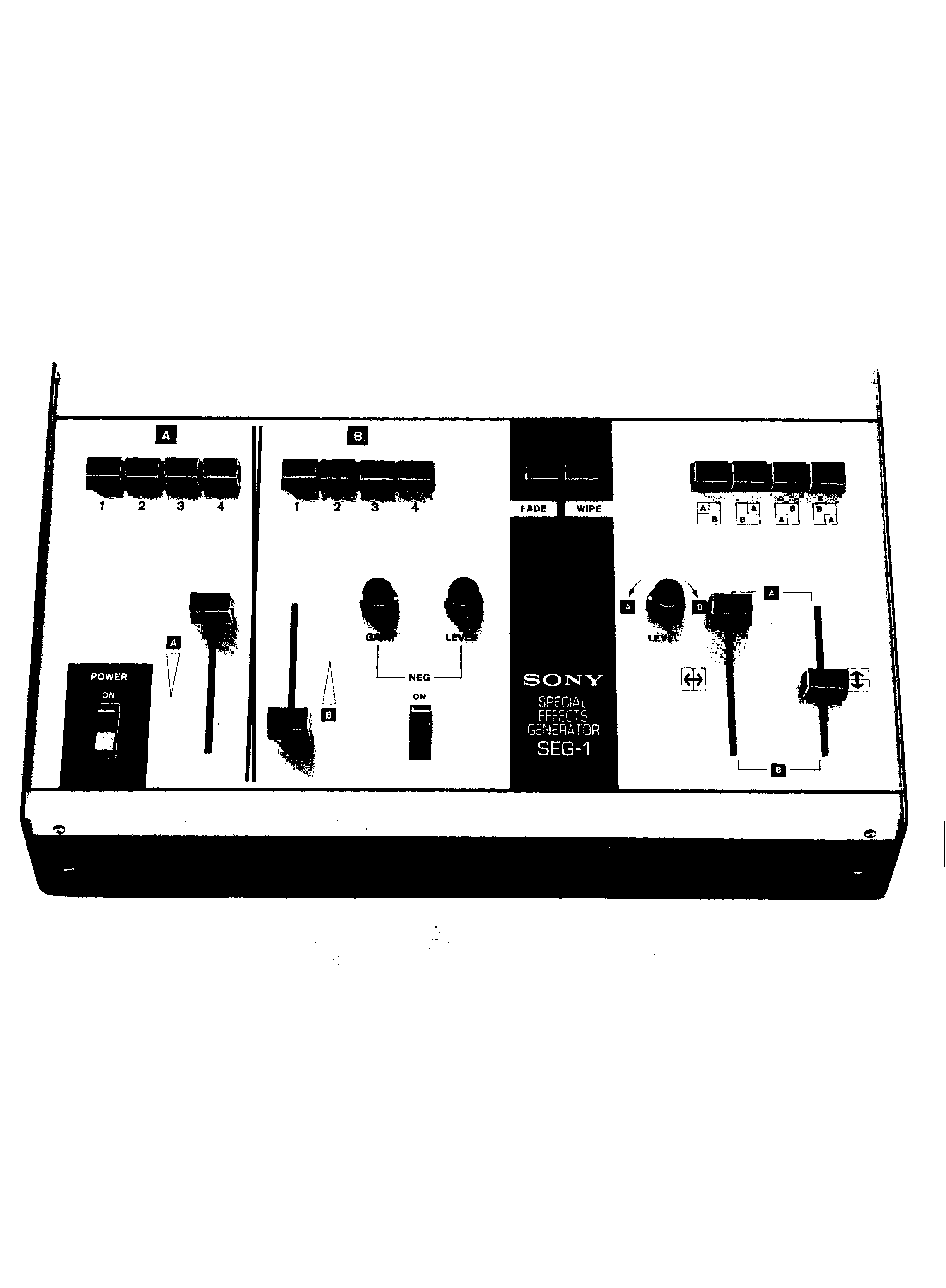
SONY Model SEG-1 is a special-effects generator
with facilities for switching, fading, superimposing,
and wiping two video signals. Inputs accept up to
four SONY video cameras and provisions are included
to monitor the output of each camera. One channel
may be inverted, if desired, to yield a negative pic-
ture. In addition, an internal sync generator supplies
2:l interlace sync, or sync may be supplied from an
external source.
The SEG-1 may be used with any SONY video camera,
monitor, and/or Videocorder. Refer to the Owner's
Instruction Manual for the complete operating pro-
cedure.
TECHNICAL
SPECIFICATIONS
Camera video inputs:
1.0 -1.4V p-p, sync neg. ,
7 5
impedance. Input 1
must be supplied with
composite video.
Number of camera inputs:
4, Hirschmann 6 Pin
receptacle
Monitor video outputs:
1.0 - 1.4V p-p, (dependent
upon input), sync negative,
75
impedance
Number of monitor outputs: 4, SO-239 UHF receptacle
Number of line outputs:
2, 1-Hirschmann 6 Pin
receptacle
1 -SO -239UHF
receptacle
Internal sync:
2:l interlace when SYNC
SELECT switch is set to
INT.
External sync:
Power requirements:
Power consumption:
Dimensions:
Weight:
Accepts vertical and hor-
izontal sync from CV-
Series Videocorders or
vertical sync (-4V p-p)
from an external 2:l EIA
sync generator.
See pin
connections below.
117V, 60Hz 3-wire parallel
ground plug
7 watts
5 1/4" H x 15 1/2" W x 10" D
8 ½ lb.
CIRCUIT DESCRIPTION
VIDEO INPUT
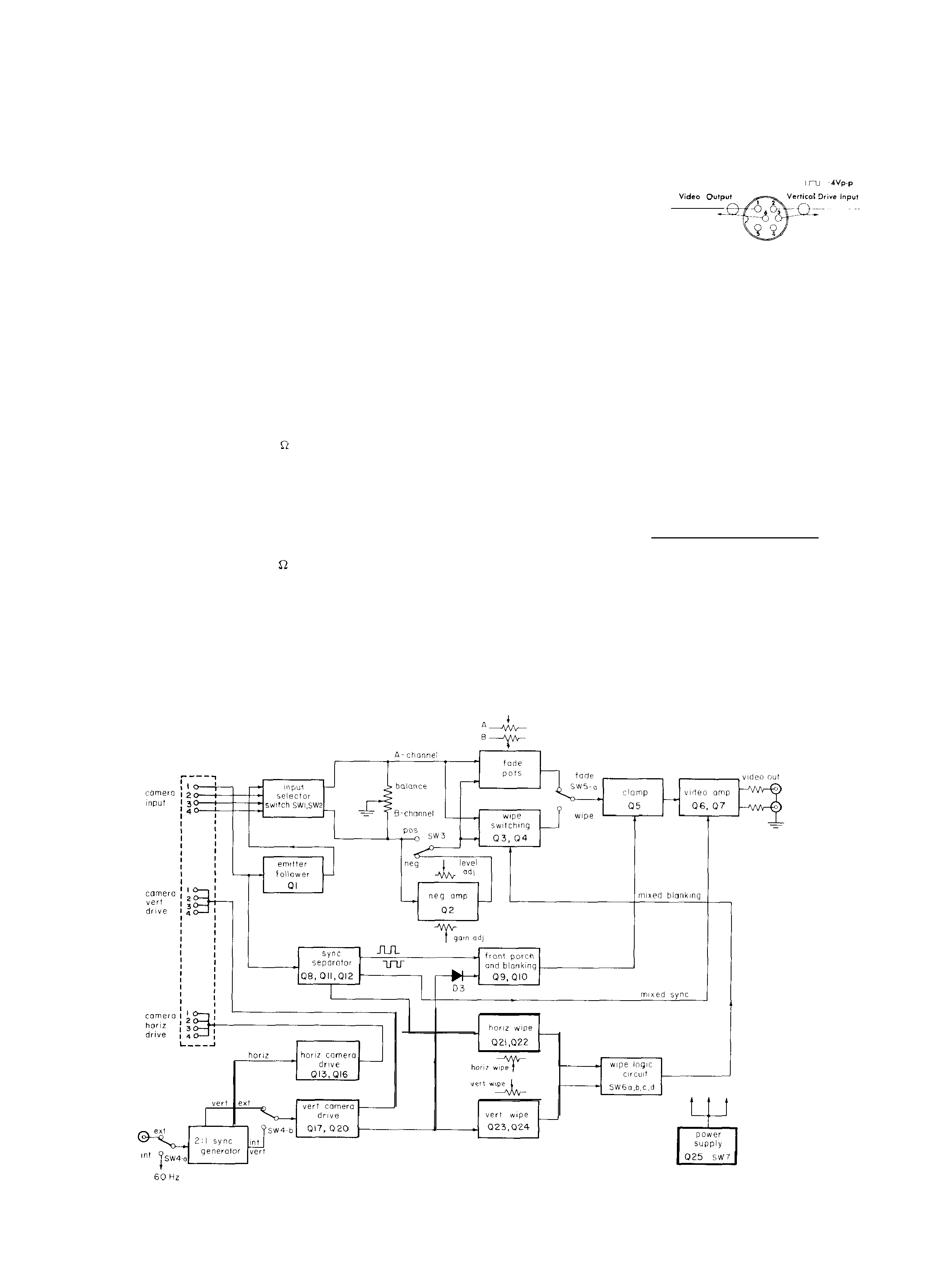
Figure 1 shows the block diagram of the SEG-1.
Up to four cameras, either 4 CV-Series or 4 DXC-Series
can be driven through Hirschmann connectors.
To de-
velop the sync pulse in the SEG-1, Camera #l must al-
ways be connected with composite video signals, while
either composite -- or non-composite -- video signal
is acceptable through Camera #2, #3 and #4.
Each cam-
era output can be monitored through four (4) source-
terminated SO-239 UHF receptacles.
Any combination of input selector switches is
accepted.
Video signals are balanced between A- and B-
channel by potentiometer VRl. If the output video
Fig. 1. Block Diagram of
SEG-1
1

levels of A- and B-channel cameras are very differ-
ent, the camera lens f-stop should be readjusted.
VIDEO INVERTER
To produce a negative picture, an inverting
one-stage amplifier, Q2, is employed in channel B.
Gain and level adjustments are accomplished by
VR2 and VR3 respectively. Either a negative or a
positive picture can be obtained on channel B by
means of SW-3.
DISSOLVE
The two selected signals are independently
attenuated by dissolve potentiometers VR4 and
VR5, mixed by R24 and R25 and, with SW5-a in
the FADE position, presented to the video ampli-
fier.
WIPES
When mode switch SW5-a is set to WIPE,
analog gates Q3 and Q4 switch rapidly between
the two selected channels in accordance with the
logic signals on their bases. The switched video
signals are mixed by R27 and R28. Logic signals
are arranged so that whenever one transistor is
turned on (turning off its video signal), the other
is turned off. This guarantees that one channel
or the other feeds the monitor at all times.
WIPE LOGIC
The logic signals that control these transistors
are derived from the horizontal and vertical sync
pulses. Each horizontal pulse triggers a one-shot
multivibrator (Q21/Q22) whose
time is deter-
mined by the setting of the horizontal wipe pot VR6.
At one extreme, a transition between channels is
produced at the left side of the screen. At the
other pot extreme, a long (60~µs) pulse is pro-
duced that delays the transition until the right
side of the screen.
Vertical wipe pot VR7 does a similar job at a
slower (O-16 ms. ) rate: Vertical one-shot Q23/Q24,
produces variable width pulses, triggered by the
vertical pulse, for horizontal direction wipes. By
using in combination independently adjustable pots
VR6 (horizontal wipe) and VR7 (vertical wipe) and
wipe selector switch, SW-6, it is possible to obtain
four corner wipes, as well as vertical and horizon-
tal wipes. The variable-duration pulses produced
by the two wipe one-shots are manipulated by resis-
tor-transistor-logic (RTL) inverters IC-1, RTL NOR
gate IC-2 and switches SW-6 to arrange the vertical,
horizontal and corner wipes.
CLAMPING
The video signal selected by mode switch SW-5
is clamped to ground during blanking time by Q5.
The horizontal blanking pulse includes front and back
porch, while the vertical blanking pulse has only a
back porch.
The horizontal blanking pulse is developed from
Camera #l and is a composite video signal.
Sync
separator Q8 produces mixed sync, which is a pos-
itive going 6 volt pulse. By means of a one-shot
multivibrator (Q 9 /Q10), a 60-µs delayed pulse occurs
about 2 µs in front of the sync pulse to form the front
porch.
The sync pulses are delayed by Cl6 to form the
horizontal back porch. The horizontal front porch,
mixed sync, horizontal back porch and the vertical
blanking pulse are added with diodes Dl -D3 to give
mixed blanking. This signal is sent to clamping
transistor, Q5.
VIDEO AMPLIFIER
A two-stage feedback amplifier (Q6/Q7) is
employed as the final stage. This gives low output
impedance to drive two 75-ohm lines. Mixed sync
from Camera #l is inserted at the output of the
video amplifier.
CAMERA DRIVE
Two modes of camera drive, external and
internal, are available.
In the SEG-1, a two-to-
one interlace sync generator is installed which is
phase locked to either incoming vertical pulses
(through a Hirschmann male receptacle) or to
internal 60 Hz line frequency.
After the sync generator, both the horizontal
and the vertical pulses are shaped by Q13 -Q16
and Ql7 -Q20 respectively. These pulse-shaping
amplifiers can drive a 19 (75
4) ohm load with a
4-volt negative-going pulse.
Due to the phase difference of horizontal
driving pulses, a combination of DXC-Series and
CVC-Series cameras is not recommended.
TRANSISTOR VOLTAGE CHART
SIGNAL PROCESSING BOARD
TRANSISTOR
B
C
E
Q1
2. 80
7. 60
2. 30
Q2
6. 90
0. 28
7. 60
Q3
0
0. 05
0
Q4
0
0. 05
0
Q5
0. 16
0. 75
0
Q6
2.10
7. 0
1. 65
Q7
7.20
1.20
8. 0
Q8
6. 20
0. 45
6. 0
Q9
0. 08
5. 0
0
QlO
6. 70
0. 73
6. 0
Q11
0. 01
5. 50
0
Q12
5. 50
6. 10
4. 8
Q13
0. 65
0. 45
0
Q14
6. 60
6. 80
7.1
Q15
6. 80
0. 82
7.1
Q16
0. 32
6. 40
0
Q17
0.10
6. 10
0
Ql8
0. 63
0. 28
0
Q19
0. 08
6. 40
0
Q20
6. 40
6. 80
5. 90
Q21
0. 08
2.40
0
Q22
7.10
4. 20
7. 50
Q23
0. 06
2. 05
0
Q24
7. 0
3. 50
7. 60
Q25
8. 0
11. 0
7. 60
All voltages above measured with a 20,000 ohms-per-volt VOM.
SYNC GENERATOR BOARD
LOCATION *
c-4
E-3
F-2
F-2
H-2
J-2
J-2
c-5
c-5
E-5
F-4
G-4
C-6
C-6
D-6
E-6
C-8
C-8
D-7
E-7
G-6
G-5
G-8
G-8
L-4
TRANSISTOR
B
C
E
LOC A TION*
Q1
-0.66
0. 58
0
B-2
Q2
0. 66
0. 55
0
c-2
Q3
0
0. 58
0. 55
D-2
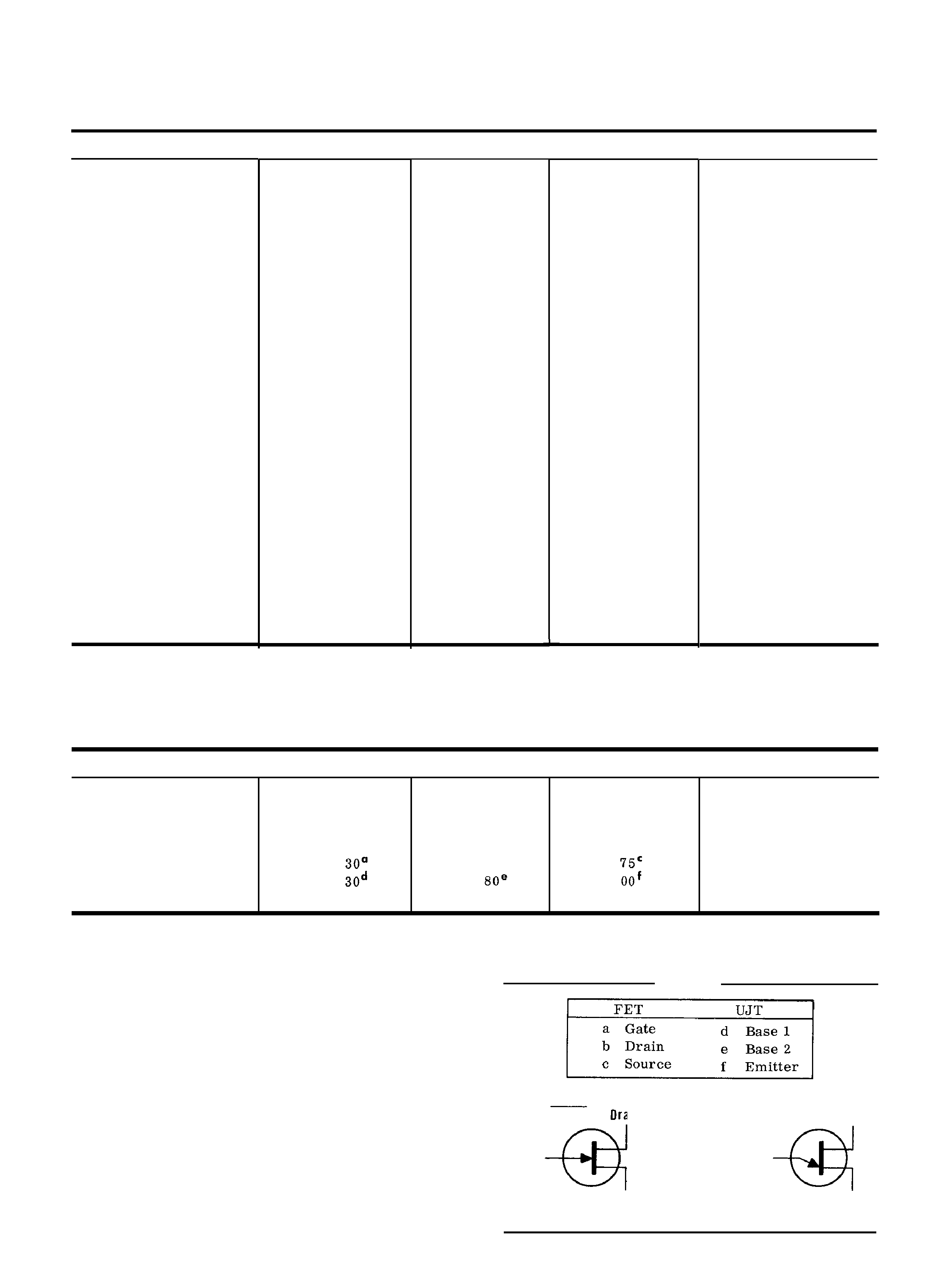
Q4 (FET)
5.
0. 58"
1.
D-2
Q5 (UJT)
0.
4.
3.
E-2
All voltages above measured with a VTVM.
SEG-1 CONTROL SETTINGS:
Channel
A Level Control = Maximum (upper position)
Channel B Level Control = Maximum (lower position)
LEVEL Control
= Center
FADE -WIPE Selector
= Fade
SYNC SELECT Switch
= INT
*Refers to Schematic Diagram Coordinates
NOTES:
FET
UJT
Drain
Gate
Base
2
Emitter
Source
Base 1
( N-Type)
3