-- 2 --
TABLE OF CONTENTS
1. SERVICING NOTE .......................................................... 3
2. GENERAL .......................................................................... 4
3. TEST MODE ..................................................................... 13
4. DIAGRAMS
4-1. Circuit Boards Location ...................................................... 14
4-2. Block Diagrams
· DA Section ....................................................................... 15
· DSP Section ..................................................................... 17
· Display Section ................................................................ 19
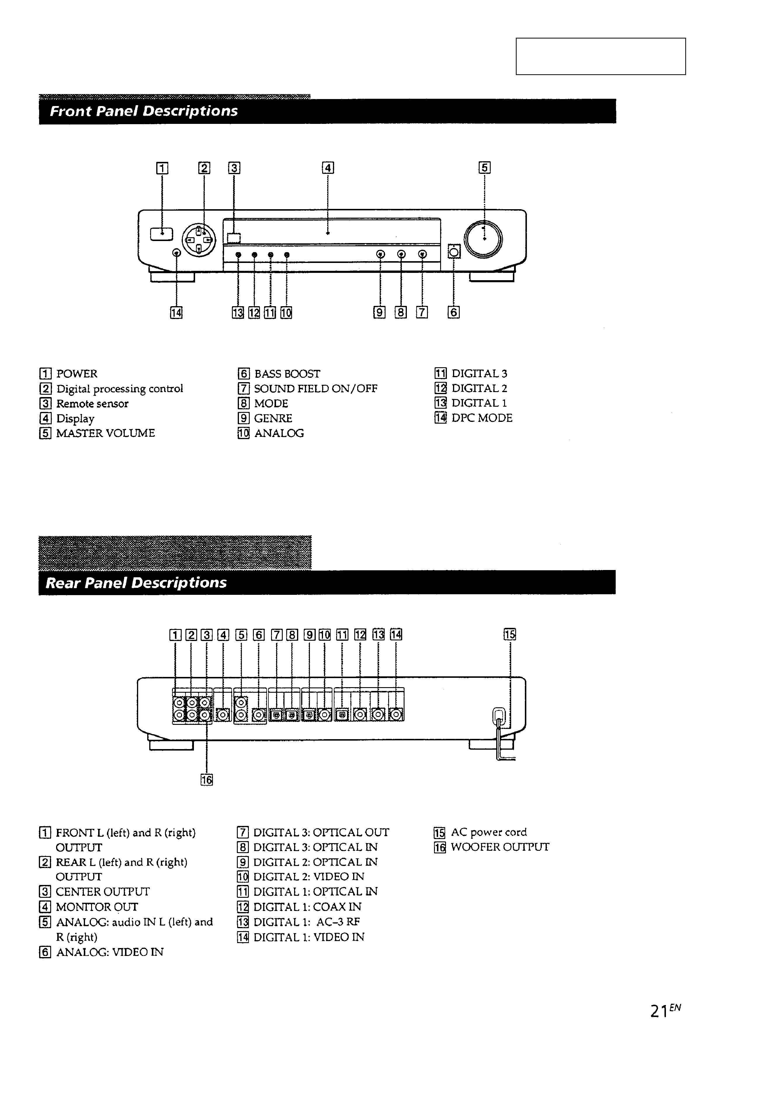
· Panel Section .................................................................... 21
· Power Section .................................................................. 21
4-3. Printed Wiring Board -- Main Section -- .......................... 23
4-4. Schematic Diagram -- D/A Section -- .............................. 27
4-5. Schematic Diagram -- Control Section -- ......................... 31
4-6. Schematic Diagram -- Dolby AC-3 Section -- ................. 35
4-7. Printed Wiring Board -- Display Section -- ...................... 38
4-8. Schematic Diagram -- Display Section -- ........................ 41
4-9. IC Block Diagrams .............................................................. 44
4-10. IC Pin Functions ................................................................ 48
5. EXPLODED VIEWS
5-1. Case Section ........................................................................ 60
5-2. Main Section ....................................................................... 61
6. ELECTRICAL PARTS LIST ........................................ 62
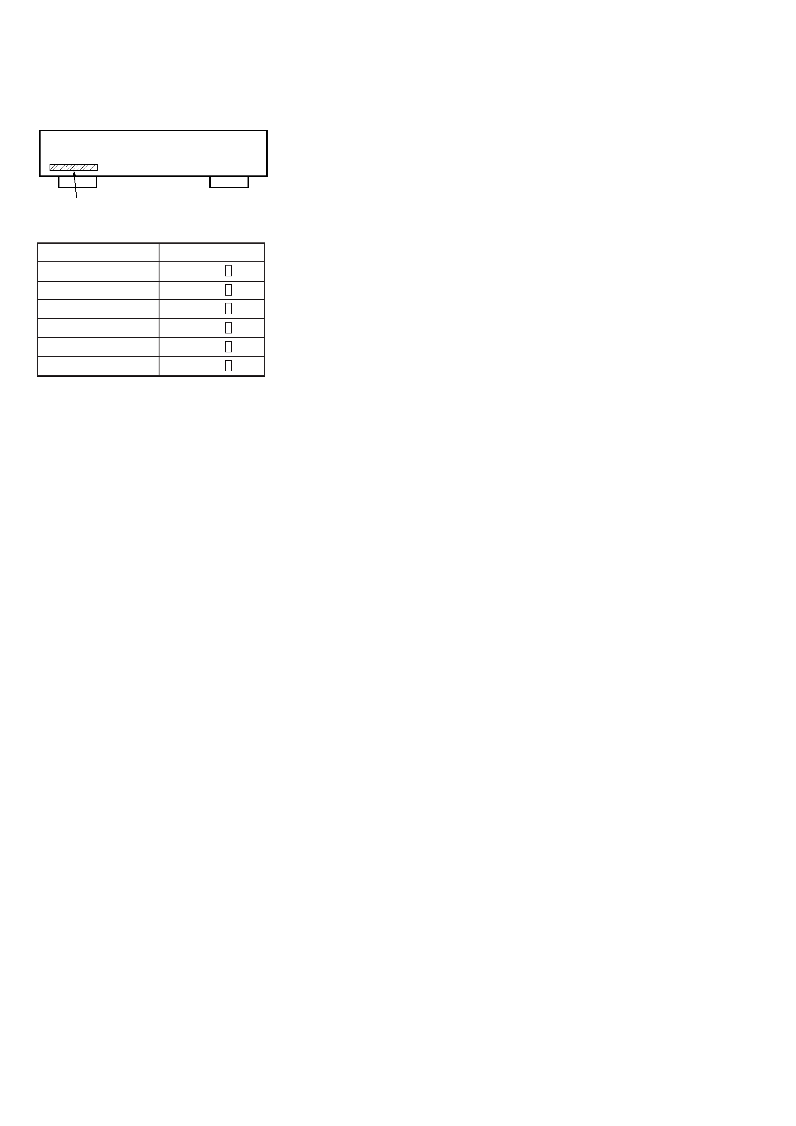
MODEL IDENTIFICATION
-- BACK PANEL --
Notes on chip component replacement
· Never reuse a disconnected chip component.
· Notice that the minus side of a tantalum capacitor may be
damaged by heat.
ATTENTION AU COMPOSANT AYANT RAPPORT
À LA SÉCURITÉ!!
LES COMPOSANTS IDENTIFIÉS PAR UNE MARQUE
!SUR
LES DIAGRAMMES SCHÉMATIQUES ET LA LISTE DES
PIÈCES SONT CRITIQUES POUR LA SÉCURITÉ DE
FONCTIONNEMENT. NE REMPLACER CES COMPOSANTS
QUE PAR DES PIÈCES SONY DONT LES NUMÉROS
SONT DONNÉS DANS CE MANUEL OU DANS LES
SUPPLÉMENTS PUBLIÉS PAR SONY.
SAFETY-RELATED COMPONENT WARNING !!
COMPONENTS IDENTIFIED BY MARK
! OR DOTTED LINE
WITH MARK
! ON THE SCHEMATIC DIAGRAMS AND IN
THE PARTS LIST ARE CRITICAL TO SAFE OPERATION.
REPLACE THESE COMPONENTS WITH SONY PARTS
WHOSE PART NUMBERS APPEAR AS SHOWN IN THIS
MANUAL OR IN SUPPLEMENTS PUBLISHED BY SONY.
Parts No.
· Abbreviation
CND : Canadian model.
SP
: Singapore model.
CH
: Chinese model.
AUS : Australian model.
· For detailed Malaysia model refer to E model.
· For detailed German, East European model refer to AEP model.
US model
E, SP model
AEP, UK model
AUS model
CND model
CH model
4-992-696-0
4-992-696-1
4-992-696-2
4-992-696-3
4-992-696-4
4-992-696-5
MODEL
PARTS No.
-- 3 --
SAFETY CHECK-OUT
After correcting the original service problem, perform the follow-
ing safety checks before releasing the set to the customer:
Check the antenna terminals, metal trim, "metallized" knobs, screws,
and all other exposed metal parts for AC leakage. Check leakage as
described below.
LEAKAGE
The AC leakage from any exposed metal part to earth Ground and
from all exposed metal parts to any exposed metal part having a
return to chassis, must not exceed 0.5 mA (500 microampers). Leak-
age current can be measured by any one of three methods.
1. A commercial leakage tester, such as the Simpson 229 or RCA
WT-540A. Follow the manufacturers' instructions to use these
instruments.
2. A battery-operated AC milliammeter. The Data Precision 245
digital multimeter is suitable for this job.
3. Measuring the voltage drop across a resistor by means of a VOM
or battery-operated AC voltmeter. The "limit" indication is 0.75
V, so analog meters must have an accurate low-voltage scale.
The Simpson 250 and Sanwa SH-63Trd are examples of a pas-
sive VOM that is suitable. Nearly all battery operated digital
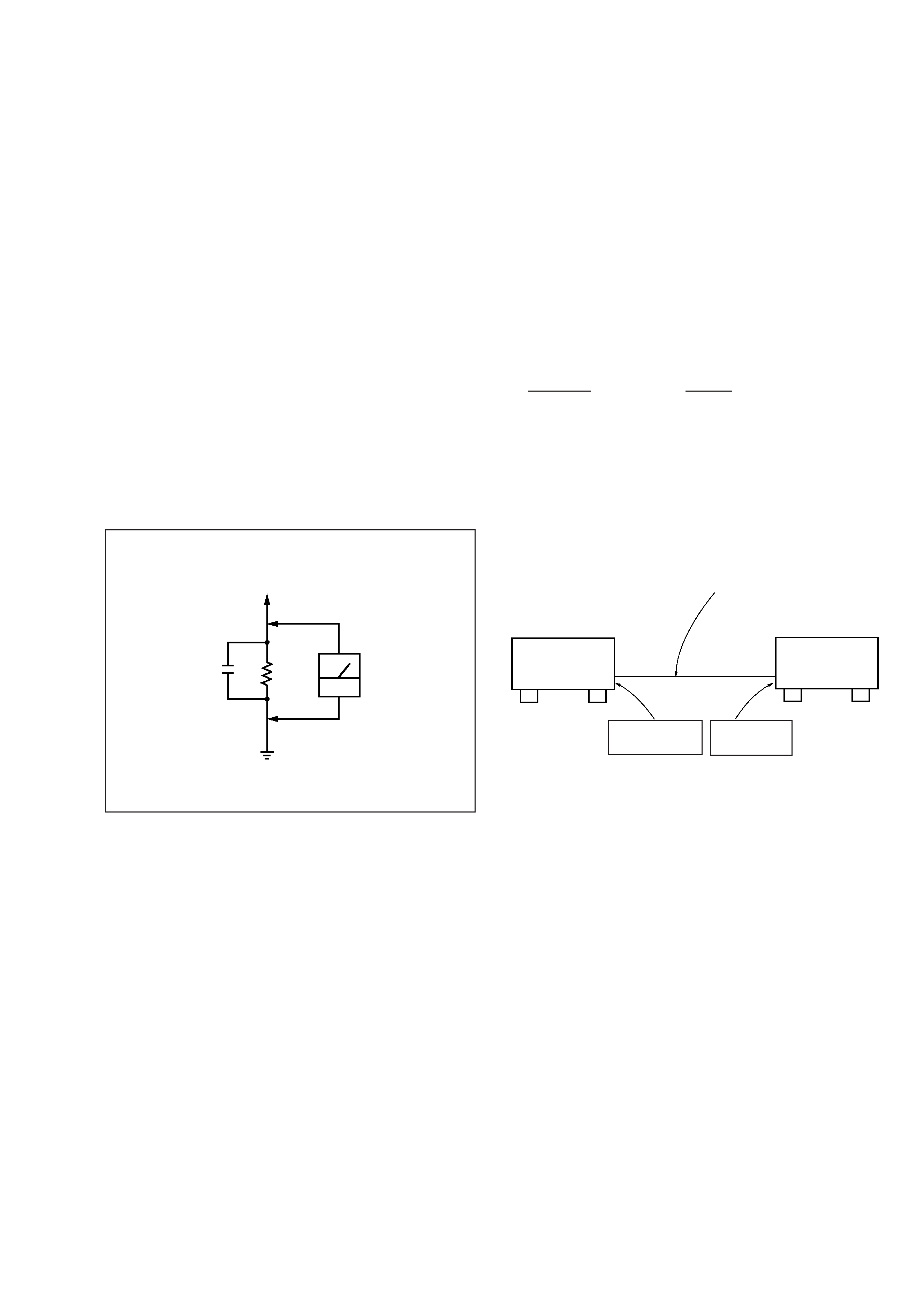
multimeters that have a 2V AC range are suitable. (See Fig. A)
Fig. A. Using an AC voltmeter to check AC leakage.
To Exposed Metal
Parts on Set
0.15
µF
1.5k
AC
voltmeter
(0.75V)
Earth Ground
SECTION 1
SERVICING NOTE
RV101 of MAIN Board
RV101 of the MAIN board requires no adjustments. Please note
that it should be dixed to mechanical center position when you moved
and do not know origin position.
L702 of PLL board
Do not touch the L702 on the PLL Board because it is not needed to
adjust.
Connection and Test Disc
Connection of this unit to a AC-3 Dolby surround equipment will
realize outstanding sound playback.
Check if the respective surround channel outputs are playing back
normally by the following method.
Jig :
Discription
Part No.
AC-3 TEST LD
J-2501-132-A
Connected Equipment:
AC-3 LD player
(This unit is also compatible with the digital versatile disc player
(DVD). The DVD must be checked with the LD player using all
the circuits of this unit.)
Connecting Method:
AC-3 RF
output terminal
AC-3 RF
input terminal
AC-3 RF output terminal Coaxial digital
connecting cable VMC-10G, etc. (Optional)
AC-3 compatible
LD player
Unit
Checking Method:
Play back a test disc of the LD player, and check if the contents
recorded on the disc case (printed on the disc case) are played
back normally.
-- 4 --
SECTION 2
GENERAL
This section is extracted from
instruction manual.
-- 5 --