SERVICE MANUAL
SPECIFICATIONS
SDM-P232W
TFT LCD Color Computer Display
US Model
Canadian Model
AEP Model
LCD panel
Panel type: a-Si TFT Active Matrix
Picture size: 23.0 inch
Input signal format
RGB operating frequency*
Horizontal:
2892 kHz (analog RGB)
2875 kHz (digital RGB)
Vertical:
4885 Hz (analog RGB)
60 Hz (digital RGB)
Resolution
Horizontal: Max.1920 dots
Vertical: Max.1200 lines
Input signal levels
Analog RGB video signal:
0.7 Vp-p, 75
, positive
SYNC signal:
TTL level, 2.2 k
positive or negative
(Separate horizontal and vertical,
or composite sync)
0.3 Vp-p, 75
, negative
(Sync on green)
Digital RGB (DVI) signal:
TMDS (Single link)
Power requirements
100240 V, 5060 Hz,
Max. 1.0 A
Power consumption
Max. 80 W
Operating temperature
535
°C
Dimensions (width/height/depth)
Display (upright):
Approx. 566
446
× 251 mm
(22 3/8
17 5/8
10 inches)
(with stand)
Approx. 566
380
114 mm
(22 3/8
15
4 1/2 inches)
(without stand)
Mass
Approx. 12.7 kg (27 lb 16 oz)
(with stand)
Approx. 10.2 kg (22 lb 8 oz)
(without stand)
Plug & Play
DDC2B
* Recommended horizontal and vertical timing condition
·
·
·
Horizontal sync width duty should be more than 4.8% of total
horizontal time or 0.8
µs, whichever is larger.
Horizontal blanking width should be more than 2.5
µsec.
Vertical blanking width should be more than 450
µsec.
Design and specifications are subject to change without notice.
×
××
×
×
×
×
SDM-P232W(E)
2
LEAKAGE TEST
The AC leakage from any exposed metal part to earth ground and from all
exposed metal parts to any exposed metal part having a return to chassis,
must not exceed 0.5 mA (500 microamperes).
Leakage current can be measured by any one of three methods.
1. A commercial leakage tester, such as the Simpson 229 or RCA WT-
540A. Follow the manufacturers' instructions to use these instruments.
2. A battery-operated AC milliammeter. The Data Precision 245 digital
multimeter is suitable for this job.
3. Measuring the voltage drop across a resistor by means of a VOM or
battery-operated AC voltmeter. The "limit" indication is 0.75 V, so
analog meters must have an accurate low-voltage scale. The Simpson 250
and Sanwa SH-63Trd are examples of a passive VOMs that are suitable.
Nearly all battery operated digital multimeters that have a 2 V AC range
are suitable. (See Fig. A)
After correcting the original service problem, perform the following safety
checks before releasing the set to the customer:
1. Check the area of your repair for unsoldered or poorly-soldered
connections. Check the entire board surface for solder splashes and
bridges.
2. Check the interboard wiring to ensure that no wires are "pinched" or
contact high-wattage resistors.
3. Check that all control knobs, shields, covers, ground straps, and
mounting hardware have been replaced. Be absolutely certain that you
have replaced all the insulators.
4. Look for unauthorized replacement parts, particularly transistors, that
were installed during a previous repair. Point them out to the customer
and recommend their replacement.
5. Look for parts which, though functioning, show obvious signs of
deterioration. Point them out to the customer and recommend their
replacement.
6. Check the line cords for cracks and abrasion. Recommend the
replacement of any such line cord to the customer.
7. Check the connector shell, metal trim, "metallized" knobs, screws, and
all other exposed metal parts for AC Leakage. Check leakage as de-
scribed right.
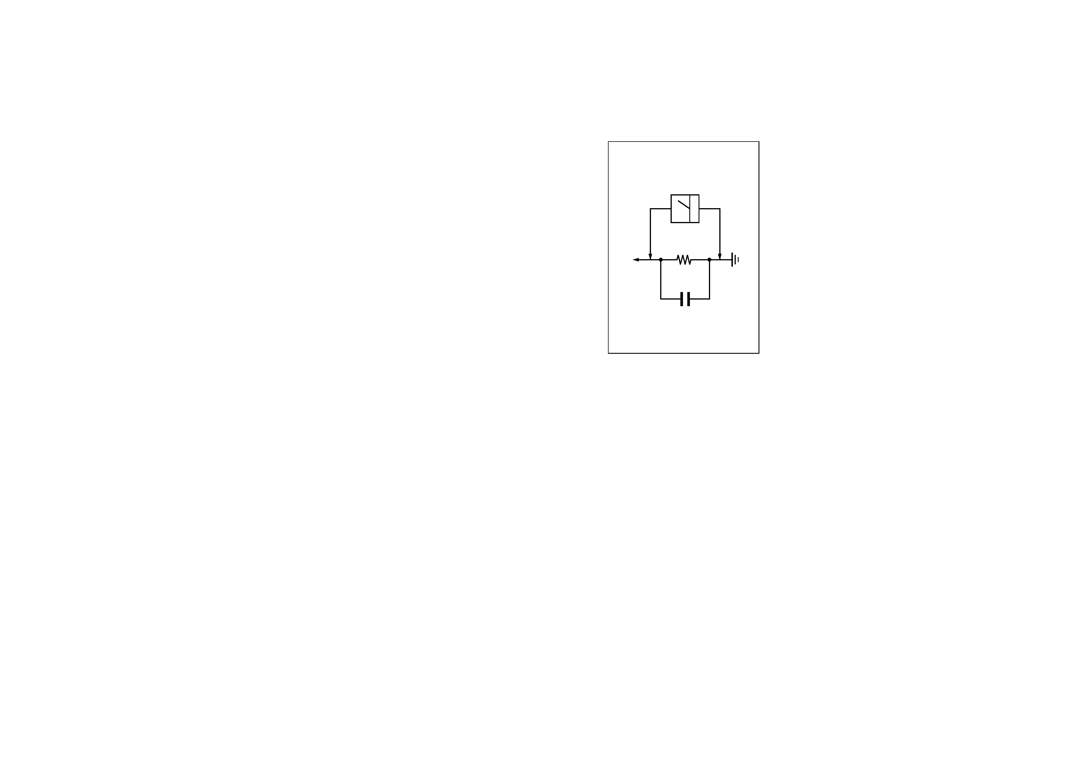
Fig. A. Using an AC voltmeter to check AC leakage.
1.5 k
0.15
µF
AC
Voltmeter
(0.75 V)
To Exposed Metal
Parts on Set
Earth Ground
SAFETY CHECK-OUT

SDM-P232W(E)
3
WARNING!!
SAFETY-RELATED COMPONENT WARNING!!
COMPONENTS IDENTIFIED BY SHADING AND MARK
! ON THE
SCHEMATIC DIAGRAMS, EXPLODED VIEWS AND IN THE
PARTS LIST ARE CRITICAL FOR SAFE OPERATION. REPLACE
THESE COMPONENTS WITH SONY PARTS WHOSE PART
NUMBERS APPEAR AS SHOWN IN THIS MANUAL OR IN
SUPPLEMENTS PUBLISHED BY SONY. CIRCUIT ADJUST-
MENTS THAT ARE CRITICAL FOR SAFE OPERATION ARE
IDENTIFIED IN THIS MANUAL. FOLLOW THESE PROCEDURES
WHENEVER CRITICAL COMPONENTS ARE REPLACED OR IM-
PROPER OPERATION IS SUSPECTED.
AVERTISSEMENT!!
ATTENTION AUX COMPOSANTS RELATIFS À LA SÉCURITÉ!!
LES COMPOSANTS IDENTIFIÉS PAR UNE TRAME ET UNE
MARQUE
! SONT CRITIQUES POUR LA SÉCURITÉ. NE LES
REMPLACER QUE PAR UNE PIÈCE PORTANT LE NUMÉRO
SPECIFIÉ. LES RÉGLAGES DE CIRCUIT DONT L'IMPORTANCE EST
CRITIQUE POUR LA SÉCURITÉ DU FONCTIONNEMENT SONT
IDENTIFIÉS DANS LE PRÉSENT MANUEL.
SUIVRE CES
PROCÉDURES LORS DE CHAQUE REMPLACEMENT DE
COMPOSANTS
CRITIQUES,
OU
LORSQU'UN
MAUVAIS
FONCTIONNEMENT EST SUSPECTÉ.

SDM-P232W(E)
4
POWER SAVING FUNCTION
AUTOMATIC PICTURE QUALITY ADJUSTMENT
FUNCTION
(ANALOG RGB SIGNAL ONLY)
This monitor meets the power-saving guidelines set by VESA,
ENERGY STAR, and NUTEK. If the monitor is connected to a
computer or video graphics board that is DPMS (Display Power
Management Signaling) compliant, the monitor will
automatically reduce power consumption as shown below.
*
When your computer enters the "active off" mode, the input signal is
cut and "No input signal" appears on the screen. After 20 seconds, the
monitor enters the power saving mode.
** "Deep sleep" is a power saving mode defined by the Environmental
Protection Agency.
Power mode
Power consumption
1
(power)
indicator
normal
operation
80 W (max.)
green
active of f*
(deep sleep)**
approx. 1 W
orange
1 (power) off
a pprox. 1 W
red
main power off
0 W
off
When the monitor receives an input signal, it
automatically adjusts the picture's position and
sharpness (phase/pitch), and ensures that a clear
picture appears on the screen.
The factory preset mode
When the monitor receives an input signal, it automatically
matches the signal to one of the factory preset modes stored in the
monitor's memory to provide a high quality picture at the center
of the screen. If the input signal matches the factory preset mode,
the picture appears on the screen automatically with the
appropriate default adjustments.
If input signals do not match one of the factory
preset modes
When the monitor receives an input signal that does not match one
of the factory preset modes, the automatic picture quality
adjustment function of this monitor is activated to ensure that a
clear picture always appears on the screen (within the following
monitor frequency ranges):
Horizontal frequency:
2892 kHz
Vertical frequency:
4885 Hz
Consequently, the first time the monitor receives input signals
that do not match one of the factory preset modes, the monitor
may take a longer time than normal to display the picture on the
screen. This adjustment data is automatically stored in memory so
that next time, the monitor will function in the same way as when
the monitor receives the signals that match one of the factory
preset modes.
If you adjust the phase, pitch, and picture position
manually
For some input signals, the automatic picture quality adjustment
function of this monitor may not completely adjust the picture
position, phase, and pitch. In this case, you can set these
adjustments manually (MANUAL, INSTRUCTION page 15).
If you set these adjustments manually, they are stored in memory
as user modes and automatically recalled whenever the monitor
receives the same input signals.
SDM-P232W(E)
5
SELF DIAGNOSIS
This monitor is equipped with a self-diagnosis function. If there is
a problem with your monitor or computer(s), the screen will go
blank and the 1 (power) indicator will light up green. If the 1
(power) indicator is lit in orange, the computer is in power saving
mode. Try pressing any key on the keyboard or moving the
mouse.
If the picture disappears from the screen and the
1 (power) indicator is green
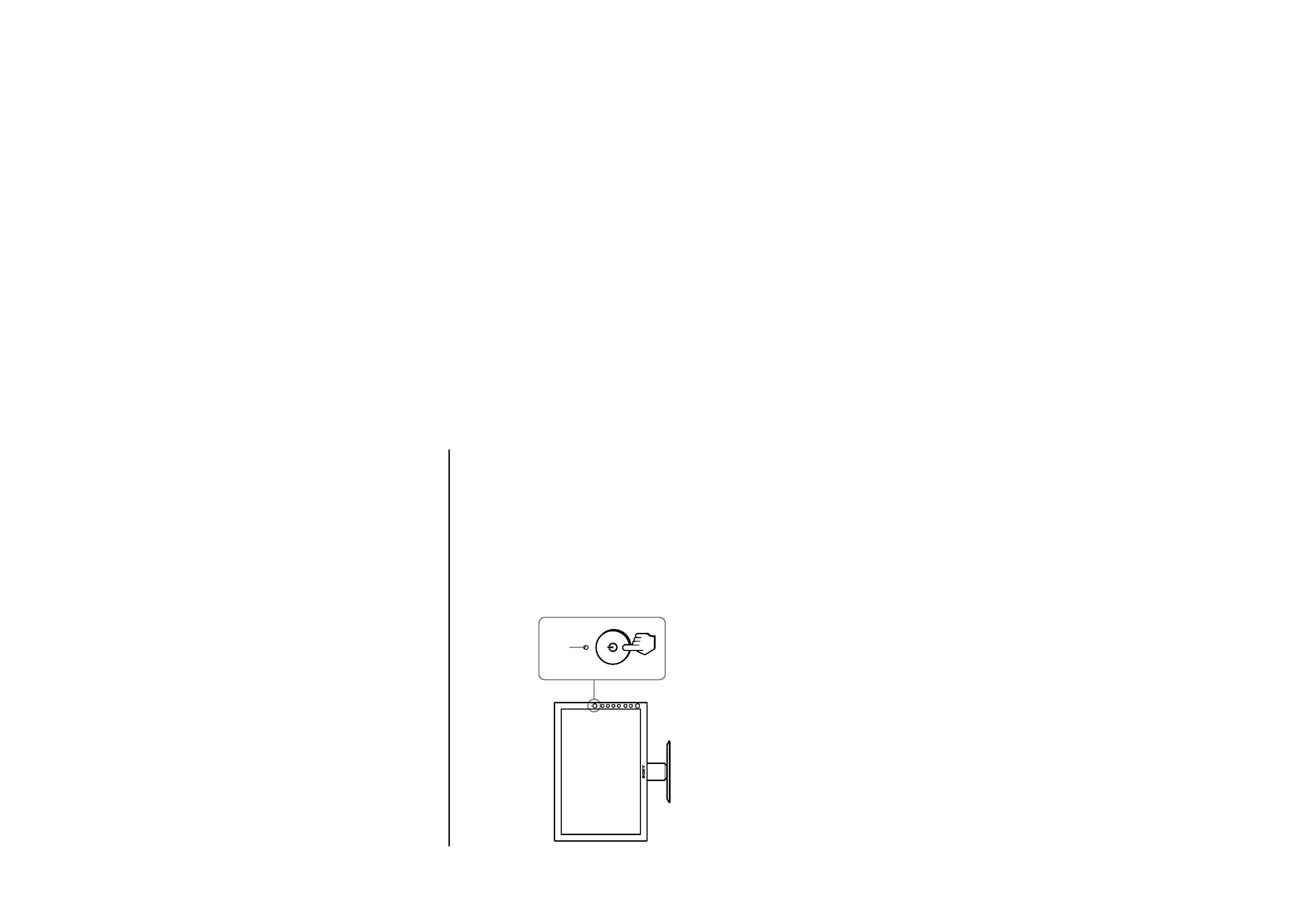
1
Turn off the 1 (power) switch and disconnect the
video signal cables from the monitor.
2
Turn the monitor on by pressing the 1 (power)
switch.
If all four color bars appear (white, red, green, blue), the monitor
is working properly. Reconnect the video input cables and check
the condition of your computer(s).
If the color bars do not appear, there is a potential monitor failure.
Inform your authorized Sony dealer of the monitor's condition.
If the 1 (power) indicator lights up in orange
Try pressing any key on the keyboard or moving the
mouse.
The computer's power saving mode is shut off and the 1 (power)
indicator lights up in green, and the picture appears on the screen.
1 (power)
indicator