CHASSIS
SERVICE MANUAL
SPECIFICATIONS
SDM-N80
SLM1
US Model
Canadian Model
AEP Model
Chassis No. SCC-L37A-A
TFT LCD COLOR COMPUTER DISPLAY
LCD panel
Panel type: a-Si TFT Active Matrix
Picture size: 18.1 inch (46 cm)
Input signal format
RGB operating frequency*
Horizontal: 28 107 kHz (analog
RGB signal)
28-92 kHz (digital RGB signal)
Vertical: 48 85 Hz**
Resolution**
Horizontal: Max.1280 dots
Vertical: Max.1024 lines
Video input connector
Analog RGB: HD15
Digital/analog RGB: DVI-I 29 pins
Input signal levels
Analog RGB video signal
0.700 Vp-p, 75
, positive
SYNC signal
TTL level, 2 k
,
positive or negative
(Separate horizontal and vertical,
or composite sync)
0.3 Vp-p, 75
,negative
(Sync on green)
Digital RGB (DVI) video signal
TMDS (Single link)
Audio output
1 W
× 2
Headphones jack
Stereo minijack
Accepts impedance of 16 48
AUDIO IN jacks
Stereo minijack
× 2
Accepts impedance of 47 k
Accepts level 0.5 Vrms
Power requirements
100 240 V, 50 60 Hz, 0.7 0.4 A
Power consumption
Max. 67 W
Operating temperature
5 35
°C
Dimensions (w/h/d)
Display (upright):
Approx. 432
400
195 mm
(17 1/8
× 15 3/4 × 7 3/4 inches)
Media engine:
Approx. 94
× 212 × 204 mm
(3 3/4
× 8 3/8 × 8 1/8 inches)
Mass
Display:
Approx. 6.5 kg (14 lb 5 oz)
Media engine:
Approx. 1.5 kg (3 lb 5 oz)
Plug & Play
DDC2B
* Recommended horizontal and vertical timing condition
Horizontal sync width duty should be more than 4.8% of total
horizontal time or 0.8
µs, whichever is larger.
Horizontal blanking width should be more than 2.5
µsec.
Vertical blanking width should be more than 450
µsec.
**A 1600
× 1200 resolution signal is acceptable only when it is a
digital RGB signal and its vertical frequency is 60 Hz.
Design and specifications are subject to change without notice.
SDM-N80 (E)
2
LEAKAGE TEST
The AC leakage from any exposed metal part to earth ground and from all
exposed metal parts to any exposed metal part having a return to chassis,
must not exceed 0.5 mA (500 microamperes).
Leakage current can be measured by any one of three methods.
1. A commercial leakage tester, such as the Simpson 229 or RCA WT-
540A. Follow the manufacturers' instructions to use these instruments.
2. A battery-operated AC milliammeter. The Data Precision 245 digital
multimeter is suitable for this job.
3. Measuring the voltage drop across a resistor by means of a VOM or
battery-operated AC voltmeter. The "limit" indication is 0.75 V, so
analog meters must have an accurate low-voltage scale. The Simpson 250
and Sanwa SH-63Trd are examples of a passive VOMs that are suitable.
Nearly all battery operated digital multimeters that have a 2 V AC range
are suitable. (See Fig. A)
After correcting the original service problem, perform the following safety
checks before releasing the set to the customer:
1. Check the area of your repair for unsoldered or poorly-soldered
connections. Check the entire board surface for solder splashes and
bridges.
2. Check the interboard wiring to ensure that no wires are "pinched" or
contact high-wattage resistors.
3. Check that all control knobs, shields, covers, ground straps, and
mounting hardware have been replaced. Be absolutely certain that you
have replaced all the insulators.
4. Look for unauthorized replacement parts, particularly transistors, that
were installed during a previous repair. Point them out to the customer
and recommend their replacement.
5. Look for parts which, though functioning, show obvious signs of
deterioration. Point them out to the customer and recommend their
replacement.
6. Check the line cords for cracks and abrasion. Recommend the
replacement of any such line cord to the customer.
7. Check the B+ and HV to see if they are specified values. Make sure your
instruments are accurate; be suspicious of your HV meter if sets always
have low HV.
8. Check the antenna terminals, metal trim, "metallized" knobs, screws, and
all other exposed metal parts for AC Leakage. Check leakage as
described below.
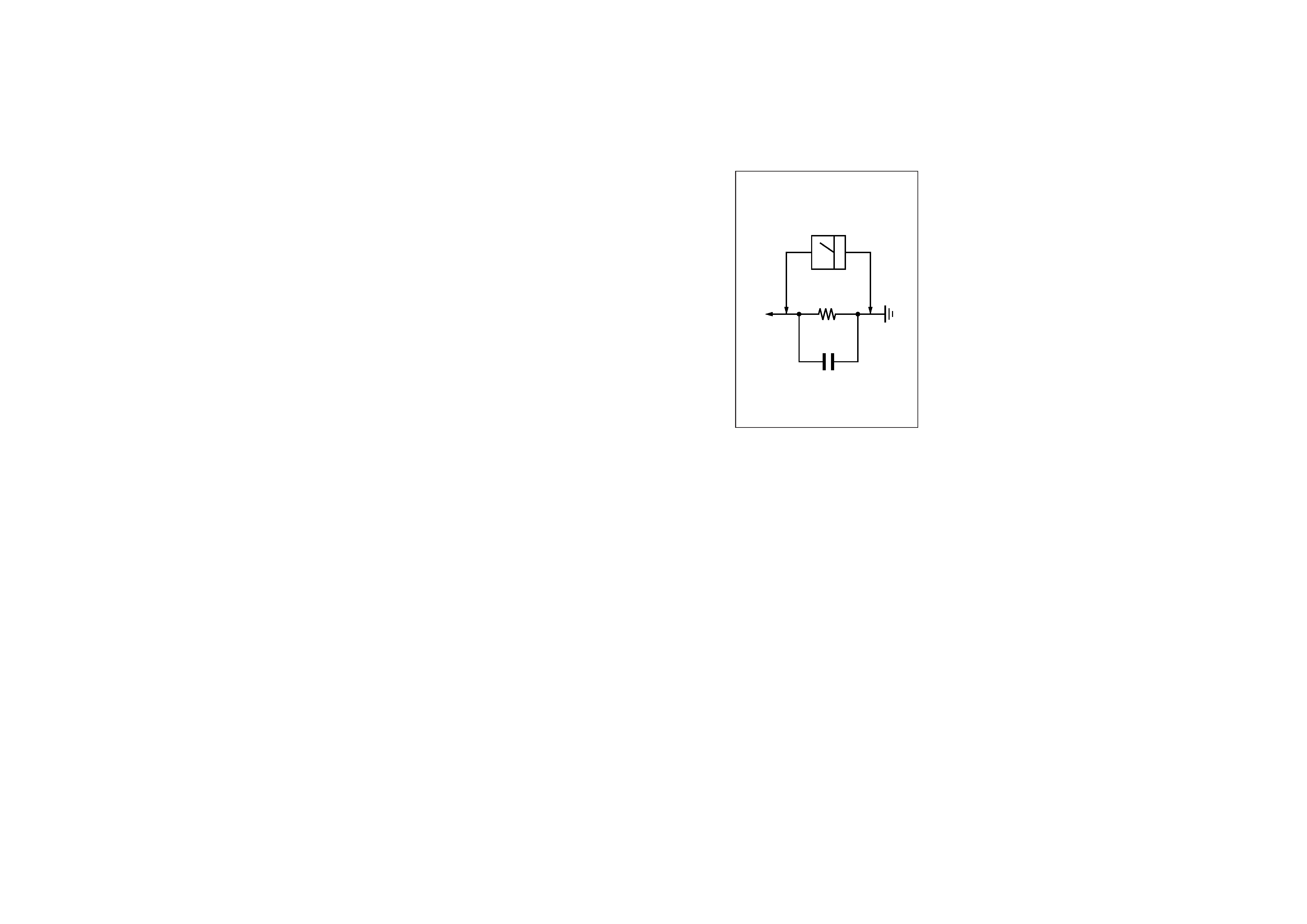
Fig. A. Using an AC voltmeter to check AC leakage.
1.5 k
0.15
µF
AC
Voltmeter
(0.75 V)
To Exposed Metal
Parts on Set
Earth Ground
SAFETY CHECK-OUT

SDM-N80 (E)
3
WARNING!!
NEVER TURN ON THE POWER IN A CONDITION IN WHICH THE
DEGAUSS COIL HAS BEEN REMOVED.
SAFETY-RELATED COMPONENT WARNING!!
COMPONENTS IDENTIFIED BY SHADING AND MARK
¡ ON THE
SCHEMATIC DIAGRAMS, EXPLODED VIEWS AND IN THE
PARTS LIST ARE CRITICAL FOR SAFE OPERATION. REPLACE
THESE COMPONENTS WITH SONY PARTS WHOSE PART
NUMBERS APPEAR AS SHOWN IN THIS MANUAL OR IN
SUPPLEMENTS PUBLISHED BY SONY. CIRCUIT ADJUST-
MENTS THAT ARE CRITICAL FOR SAFE OPERATION ARE
IDENTIFIED IN THIS MANUAL. FOLLOW THESE PROCEDURES
WHENEVER CRITICAL COMPONENTS ARE REPLACED OR IM-
PROPER OPERATION IS SUSPECTED.
AVERTISSEMENT!!
NE JAMAIS METTRE SOUS TENSION QUAND LA BOBINE DE
DEMAGNETISATION EST ENLEVÉE.
ATTENTION AUX COMPOSANTS RELATIFS À LA SÉCURITÉ!!
LES COMPOSANTS IDENTIFIÉS PAR UNE TRAME ET UNE
MARQUE
¡ SONT CRITIQUES POUR LA SÉCURITÉ. NE LES
REMPLACER QUE PAR UNE PIÈCE PORTANT LE NUMÉRO
SPECIFIÉ. LES RÉGLAGES DE CIRCUIT DONT L'IMPORTANCE EST
CRITIQUE POUR LA SÉCURITÉ DU FONCTIONNEMENT SONT
IDENTIFIÉS DANS LE PRÉSENT MANUEL.
SUIVRE CES
PROCÉDURES LORS DE CHAQUE REMPLACEMENT DE
COMPOSANTS
CRITIQUES,
OU
LORSQU'UN
MAUVAIS
FONCTIONNEMENT EST SUSPECTÉ.
SDM-N80 (E)
4
POWER SAVING FUNCTION
This monitor meets the power-saving guidelines set by VESA,
ENERGY STAR, and NUTEK. If the monitor is connected to a computer
or video graphics board that is DPMS (Display Power Management Signaling) compliant, the monitor will automatically enter the power
saving mode. It automatically enters the low power consumption mode when the user sensor detects the absence of a user.
*Figures reflect power consumption when the computer connected to the USB upstream connector on the monitor is turned off.
Power consumption state
Power consumption
AC power indicator
(power) indicator
normal operation
W
green
green
1 low power consumption mode
W*
green
green and orange alternate
2 power saving mode
W*
orange
orange
(power): off
W
red
off
AC power: off
0 W
off
off
< 67
< 8.5
< 1.3
< 1

SDM-N80 (E)
5
1 Low power consumption mode (user sensor)
When the user sensor in the monitor detects the absence of a user,
the monitor enters low power consumption mode after about 20
seconds. The icon of user sensor appears and flashes on the screen
before the monitor enters this mode. In low power consumption
mode, the monitor is in a power saving state and shuts off power
to all circuitry (except for that of the sensors) regardless of the
setting of the computer.
The monitor returns to normal operation mode when the presence
of a user is detected by the user sensor.
When the monitor enters the power saving mode (as set according
to the computer's settings), the power saving mode takes
precedence over the low power consumption mode. In this case,
the monitor stays in the power saving mode regardless of the
presence or absence of a user.
To return the monitor to normal operation mode, reset the
computer's power saving mode.
If the user sensor does not seem to function properly, refer to the
instructions on the next page.
2 Power saving mode
DPMS defines the active off state according to the state of the
sync signals supplied from the computer. This monitor's power
consumption is input at approximately 1.3 W or less in this state
if the power saving function is set to ON.
When your computer enters the power saving mode, the input
signal is cut and NO INPUT SIGNAL appears on the screen.
After a few seconds, the monitor enters power saving mode.
* "Deep sleep" is a power saving mode defined by the Environmental
Protection Agency.
Notes
· The power saving function may not work normally depending on the
pattern of supplied sync signals. In such a case, set the power saving
function to OFF.
· When you connect a computer whose power is connected to the USB
upstream connector on the monitor, the monitor will not enter the
power saving mode.
Power saving
state
Sync signal state
active off (deep sleep)*
horizontal: off / vertical: off