MODIFICATION # No. DATE
CONTENTS
#1
2001.10 Add P/N of pending parts.(P.4-2)
#2
2001.10 Parts number error correction.(P.5-8)
#3
2001.12 Add P/N of pending parts.(P.5-14)
MODEL NAME:
#4
2001.12 Addition of parts number of Black Model in exploded views. (P.4-1, 4-2)
SDM-M51D
SERVICE MANUAL
PARTS No.: 9-978-699-03
* Blue characters are linking.
HISTORY
SDM-M51D
SERVICE MANUAL
US Model
Canadian Model
AEP Model
SPECIFICATIONS
LCD panel
Input signal format
Resolution
Video input connector
Input signal levels
Audio output
Headphones jack
Audio in jack
Panel type: a-Si TFT Active Matrix
Picture size: 15.1 inch
RGB operating frequency*
Horizontal: 28-64 kHz
Vertical: 48-75 Hz
Horizontal: Max. 1024 dots
Vertical: Max. 768 lines
Analog RGB: HD15
Digital/Analog RGB: DVI-I 29 pins
Analog RGB video signal:
0.7 Vp-p, 75, positive
SYNC signal:
TTL level, 2.2k,
Positive or negative
(Separate horizontal and vertical,
or composite sync)
0.3 Vp-p, 75, negative
(Sync on green)
Digital RGB video signal:
TMDS (single link)
1W x 2
Stereo minijack
Accepts impedance of 16-48
Stereo minijack
Accepts impedance of 47 k
Accepts level 0.5 Vrms
Power requirements
100-240 V, 50-60 Hz,
0.4 - 0.2A (including AC adapter)
Power consumption
Max. 22W (including AC adapter)
Operating temperature
5-35
Dimensions (width/height/depth)
Display (upright):
Approx. 387 x 345 x 180 mm
(15¼ x 13 x 7 inches)
(with stand)
Approx. 387 x 296 x 48 mm
(15¼ x 11¾ x 115/16 inches)
(without stand)
Mass
Approx. 4.6 kg (10 1b 14 oz) (with
stand)
Plug & Play
DDC2B
* Recommended horizontal and vertical timing condition
· Horizontal sync width duty should be more than 4.8% of total
horizontal time or 0.8 s, whichever is larger.
· Horizontal blanking width should be more than 2.5 sec.
· Vertical blanking width should be more than 450sec.
Design and specifications are subject to change without notice.
TFT LCD COLOR COMPUTER DISPLAY

SDM-M51D
Power saving function
This monitor meets the power-saving guidelines set by VESA,
ENERGY STAR, and NUTEK. If the monitor is connected to a
computer or video graphics board that is DPMS (Display Power
Management Signaling) compliant, the monitor will automatically
reduce power consumption in three stages as shown below.
*
"deep sleep" is the power saving mode defined by the Environmental
Protection Agency.
** When your computer enters the "active off" mode, the input signal is
cut and NO INPUT SIGNAL appears on the screen. After 20 seconds,
the monitor enters the power saving mode.
*** If the horizontal or vertical sync signal is received by the monitor, the
power indicator may alternately blink green and orange.
Automatic picture quality
adjustment function
When the monitor receives an input signal, it automatically
matches the signal to one of the factory preset modes stored in the
monitor's memory to provide a high quality picture at the center
of the screen. (See Appendix for a list of the factory preset
modes.)
For input signals that do not match one of the factory preset
modes, the automatic picture quality adjustment function of this
monitor automatically adjusts the picture position, phase, and
pitch, and ensures that a clear picture appears on the screen for
any timing within the monitor's frequency range (horizontal: 28
64 kHz, vertical: 48 75 Hz).
Consequently, the first time the monitor receives input signals
that do not match one of the factory preset modes, the monitor
may take a longer time than normal for displaying the picture on
the screen. This adjustment data is automatically stored in
memory so that next time, the monitor will function in the same
way as when the monitor receives the signals that match one of
the factory preset modes.
In all modes as above, if the picture is adjusted, the adjustment
data is stored as a user mode and automatically recalled whenever
the same input signal is received.
Note
While the automatic picture quality adjustment function is activated, only
the 1 (power) switch will operate.
Power mode
Power
consumption*
1
(power)
indicator
normal
operation
22 W (max.)
green
active off**
(deep sleep)*
2 W (max.)
orange***
power off
2 W (max.)
off
SDM-M51D(E)
-2-
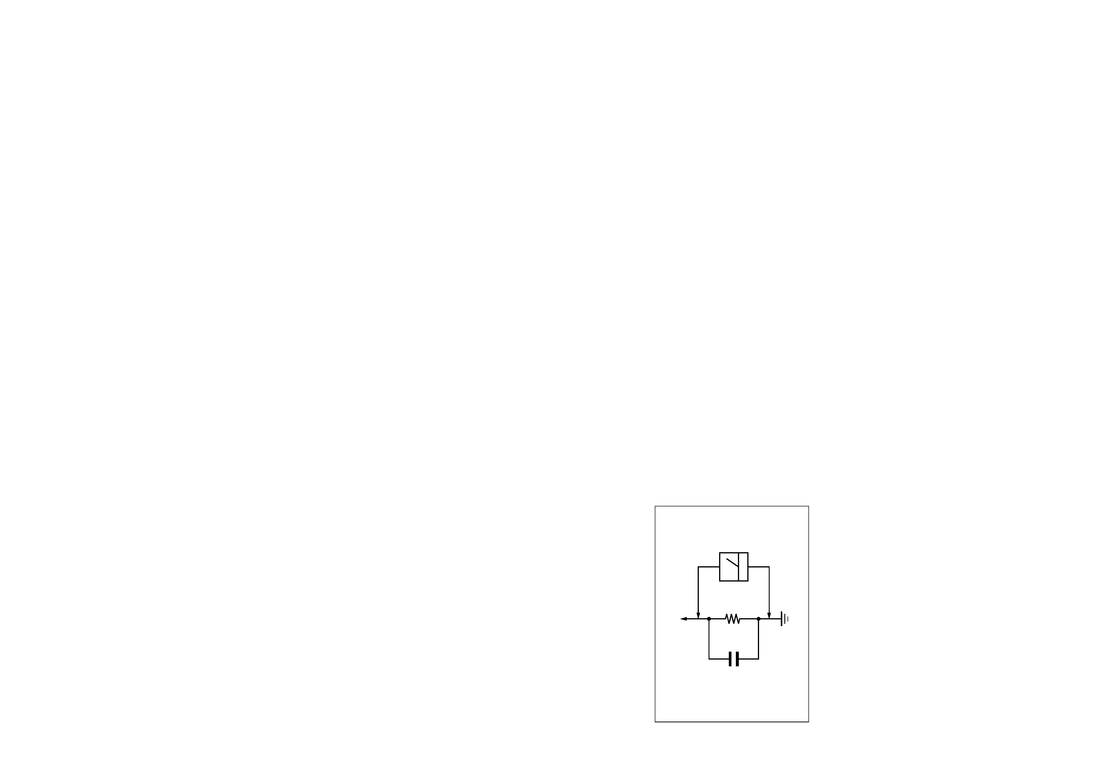
Fig. A. Using an AC voltmeter to check AC leakage.
SAFETY CHECK-OUT
1.5 k
0.15
µF
AC
Voltmeter
(0.75 V)
To Exposed Metal
Parts on Set
Earth Ground
SDM-M51D
LEAKAGE TEST
The AC leakage from any exposed metal part to earth ground
and from all exposed metal parts to any exposed metal part hav-
ing a return to chassis, must not exceed 0.5 mA (500
microampers).
Leakage current can be measured by any one of three methods.
1. A commercial leakage tester, such as the Simpson 229 or
RCA WT-540A. Follow the manufacturers' instructions to
use these instruments.
2. A battery-operated AC milliammeter. The Data Precision
245 digital multimeter is suitable for this job.
3. Measuring the voltage drop across a resistor by means of a
VOM or battery-operated AC voltmeter. The "limit" indica-
tion is 0.75 V, so analog meters must have an accurate low-
voltage scale. The Simpson 250 and Sanwa SH-63Trd are
examples of a passive VOMs that are suitable. Nearly all
battery operated digital multimeters that have a 2 V AC
range are suitable. (See Fig. A)
WARNING!!
NEVER TURN ON THE POWER IN A CONDITION IN
WHICH THE DEGAUSS COIL HAS BEEN REMOVED.
SAFETY-RELATED COMPONENT WARNING!!
COMPONENTS IDENTIFIED BY SHADING AND MARK
¡ ON THE SCHEMATIC DIAGRAMS, EXPLODED
VIEWS AND IN THE PARTS LIST ARE CRITICAL FOR
SAFE OPERATION. REPLACE THESE COMPONENTS
WITH SONY PARTS WHOSE PART NUMBERS AP-
PEAR AS SHOWN IN THIS MANUAL OR IN SUPPLE-
MENTS PUBLISHED BY SONY. CIRCUIT ADJUST-
MENTS THAT ARE CRITICAL FOR SAFE OPERATION
ARE IDENTIFIED IN THIS MANUAL. FOLLOW THESE
PROCEDURES WHENEVER CRITICAL COMPONENTS
ARE REPLACED OR IMPROPER OPERATION IS SUS-
PECTED.
After correcting the original service problem, perform the fol-
lowing safety checks before releasing the set to the customer:
1. Check the area of your repair for unsoldered or poorly-sol-
dered connections. Check the entire board surface for solder
splashes and bridges.
2. Check the interboard wiring to ensure that no wires are
"pinched" or contact high-wattage resistors.
3. Check that all control knobs, shields, covers, ground straps,
and mounting hardware have been replaced. Be absolutely
certain that you have replaced all the insulators.
4. Look for unauthorized replacement parts, particularly tran-
sistors, that were installed during a previous repair. Point
them out to the customer and recommend their replacement.
5. Look for parts which, though functioning, show obvious
signs of deterioration. Point them out to the customer and
recommend their replacement.
6. Check the line cords for cracks and abrasion. Recommend
the replacement of any such line cord to the customer.
7. Check the B+ and HV to see if they are specified values.
Make sure your instruments are accurate; be suspicious of
your HV meter if sets always have low HV.
8. Check the antenna terminals, metal trim, "metallized"
knobs, screws, and all other exposed metal parts for AC
Leakage. Check leakage as described below.
AVERTISSEMENT!!
NE JAMAIS METTRE SOUS TENSION QUAND LA
BOBINE DE DEMAGNETISATION EST ENLEVÉE.
ATTENTION AUX COMPOSANTS RELATIFS À LA
SÉCURITÉ!!
LES COMPOSANTS IDENTIFIÉS PAR UNE TRAME ET
UNE MARQUE
¡ SONT CRITIQUES POUR LA SÉCURITÉ.
NE LES REMPLACER QUE PAR UNE PIÈCE PORTANT LE
NUMÉRO SPECIFIÉ. LES RÉGLAGES DE CIRCUIT DONT
L'IMPORTANCE EST CRITIQUE POUR LA SÉCURITÉ DU
FONCTIONNEMENT SONT IDENTIFIÉS DANS LE
PRÉSENT MANUEL. SUIVRE CES PROCÉDURES LORS
DE CHAQUE REMPLACEMENT DE COMPOSANTS CRI-
TIQUES, OU LORSQU'UN MAUVAIS FONCTIONNEMENT
EST SUSPECTÉ.
.
SDM-M51D(E)
-3-

TABLE OF CONTENTS
Section
Title
Page
1. DISASSEMBLY
1-1. Bezel Assy, and Back Cabinet Removal
1-2. TFT Panel and Chassis Removal
Inverter Board Removal
1-3. A Board Removal
2. ADJUSTMENTS
2-1. Adjustment (1)
2-2. Adjustment (2)
2-3. Table (1) & (2)
2-4. Timing Specification
3. SCHEMATIC DIAGRAMS
3-1. Note
3-2. Block Diagrams
3-3. (1) Schematic Diagram of A (a-e) Board
(2) Schematic Diagram of H Board
(3) Schematic Diagram of J Board
4. EXPLODED VIEWS
4-1. LCD Monitor
4-2. Packing Materials
5. ELECTRICAL PARTS LIST
SDM-M51D(E)
-4-
1-1
1-2
1-2
1-3
2-1
2-2
2-3
2-4
3-1
3-2
3-3
3-10
3-11
4-1
4-2
5-1