MICROFILM
SCT-ID10
SERVICE MANUAL
ID TELEPHONE CLOCK RADIO
SPECIFICATIONS
US Model
Canadian Model
Frequency range
FM : 87.5 108 MHz
AM : 530 1,605 kHz
Speaker
Approx. 6.6 cm (2 5/8 inches) dia., 8 ohms
Power output
100 mW (at 10% harmonic distortion)
Dial signal :
Tone, pulse selectable
Power requirements :
120V AC, 60Hz
For power backup :
9V DC, one 6F22 battery (Functions for clock radio only)
Battery life :
Approx. 35 hours using the Sony S-006P (U) battery
Dimensions :
Approx. 250 x 98.6 x 202 mm (w/h/d)
(9 7/8 x 4 x 8 inches) incl. projecting parts and controls
Mass
Approx. 880g (2 lb. 31 oz) not incl. battery
Supplied accessories
Telephone line cord (1 )
Handset cord (1 )
Design and specifications are subject to change without notice.
Ver 1.0
1998.03
2
SAFETY-RELATED COMPONENT WARNING!!
COMPONENTS IDENTIFIED BY MARK
! OR DOTTED LINE WITH
MARK
! ON THE SCHEMATIC DIAGRAMS AND IN THE PARTS
LIST ARE CRITICAL TO SAFE OPERATION.
REPLACE THESE COMPONENTS WITH SONY PARTS WHOSE
PART NUMBERS APPEAR AS SHOWN IN THIS MANUAL OR IN
SUPPLEMENTS PUBLISHED BY SONY.
TABLE OF CONTENTS
Specifications ........................................................................... 1
1. GENERAL
Location and Function of Controls .................................... 3
2. DISASSEMBLY
2-1. Key Board, Cabinet (Upper) Assy Removal .............. 7
2-2. Main Board, Transformer Board, Transformer
retainer Board, Battery Blind Board Removal ........... 7
2-3. Cabinet (Top) Removal .............................................. 8
Installation Power Cord .............................................. 8
3. DIAL POINTER INSTALLATION ............................ 9
4. TEST MODE ................................................................. 10
5. ELECTRICAL ADJUSTMENTS ............................ 11
6. DIAGRAMS
6-1. Explanation of IC Terminals ..................................... 12
6-2. Block Diagram .......................................................... 13
6-3. Printed Wiring Boards (Main Section) ..................... 15
6-4. Schematic Diagram (Main Section) ......................... 17
6-5. Printed Wiring Boards (Key Section) ....................... 19
6-6. Schematic Diagram (Key Section) ........................... 21
7. EXPLODED VIEWS
7-1. Base Unit Section ..................................................... 24
7-2. Handset Section ........................................................ 25
8. ELECTRICAL PARTS LIST .................................... 26
SAFETY CHECK-OUT (US model)
After correcting the original service problem, perform the
following safety check before releasing the set to the customer :
Check the antenna terminals, metal trim, "metallized" knobs,
screws, and all other exposed metal parts for AC leakage. Check
leakage as described below.
LEAKAGE TEST
The AC leakage from any exposed metal part to earth ground and
from all exposed metal parts to any exposed metal part having a
return to chassis, must not exceed 0.5mA (500 microampers).
Leakage current can be measured by any one of three methods.
1. A commercial leakage tester, such as the Simpson 229 or RCA
WT-540A. Follow the manufacturers' instructions to use these
instruments.
2. A battery-operated AC milliammeter. The Data Precision 245
digital multimeter is suitable for this job.
3. Measuring the voltage drop across a resistor by means of a VOM
or battery-operated AC voltmeter. The "limit" indication is 0.75V,
so analog meters must have an accurate low-voltage scale. The
Simpson 250 and Sanwa SH-63Trd are examples of a passive
VOM that is suitable. Nearly all battery operated digital
multimeters that have a 2V AC range are suitable. (See Fig. A)
AC
voltmeter
(0.75V)
To Exposed Metal
Parts on Set
Earth Ground
0.15
µF
1.5k
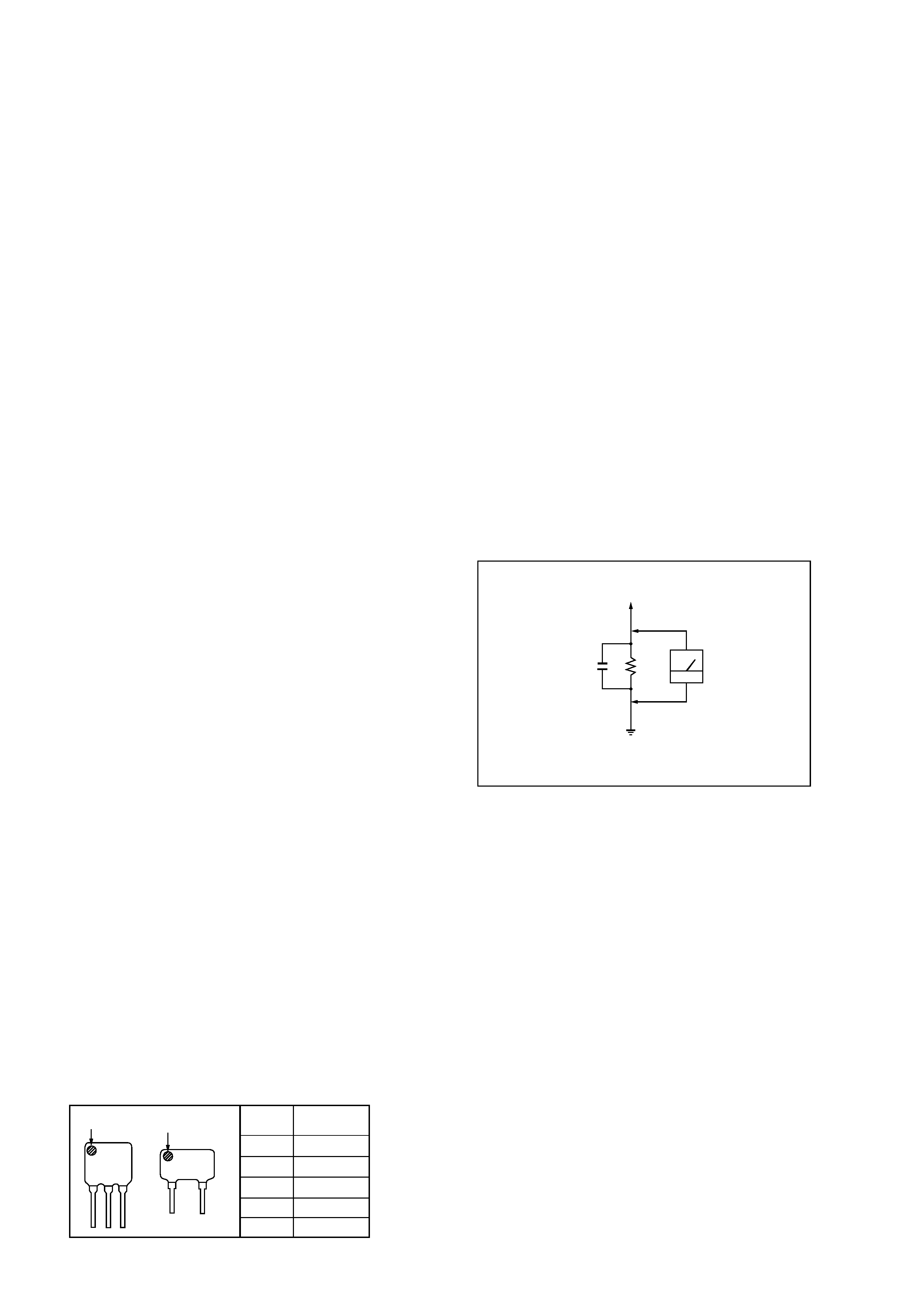
Fig. A. Using an AC voltmeter to check AC leakage.
Notes on chip component replacement
· Never reuse a disconnected chip component.
· Notice that the minus side of a tantalum capacitor may be dam-
aged by heat.
ATTENTION AU COMPOSANT AYANT RAPPORT
À LA SÉCURITÉ!
LES COMPOSANTS IDENTIFIÉS PAR UNE MARQUE
! SUR LES
DIAGRAMMES SCHÉMATIQUES ET LA LISTE DES PIÈCES SONT
CRITIQUES POUR LA SÉCURITÉ DE FONCTIONNEMENT. NE
REMPLACER CES COMPOSANTS QUE PAR DES PIÈCES SONY
DONT LES NUMÉROS SONT DONNÉS DANS CE MANUEL OU
DANS LES SUPPLÉMENTS PUBLIÉS PAR SONY.
· HOW TO CHANGE THE CERAMIC FILTER
This model is used two ceramic filters of CF3 and CF1.
You must use same type of color marked ceramic filters in order
to meet same specifications.
Therefore, the ceramic filter must change two pieces together since
it's supply two pieces in package as a spare parts.
mark
mark
CF1
CF3
red
10.70MHz
blue
10.67MHz
orange
10.73MHz
black
10.64MHz
white
10.76MHz
Mark
Center
frequency
3
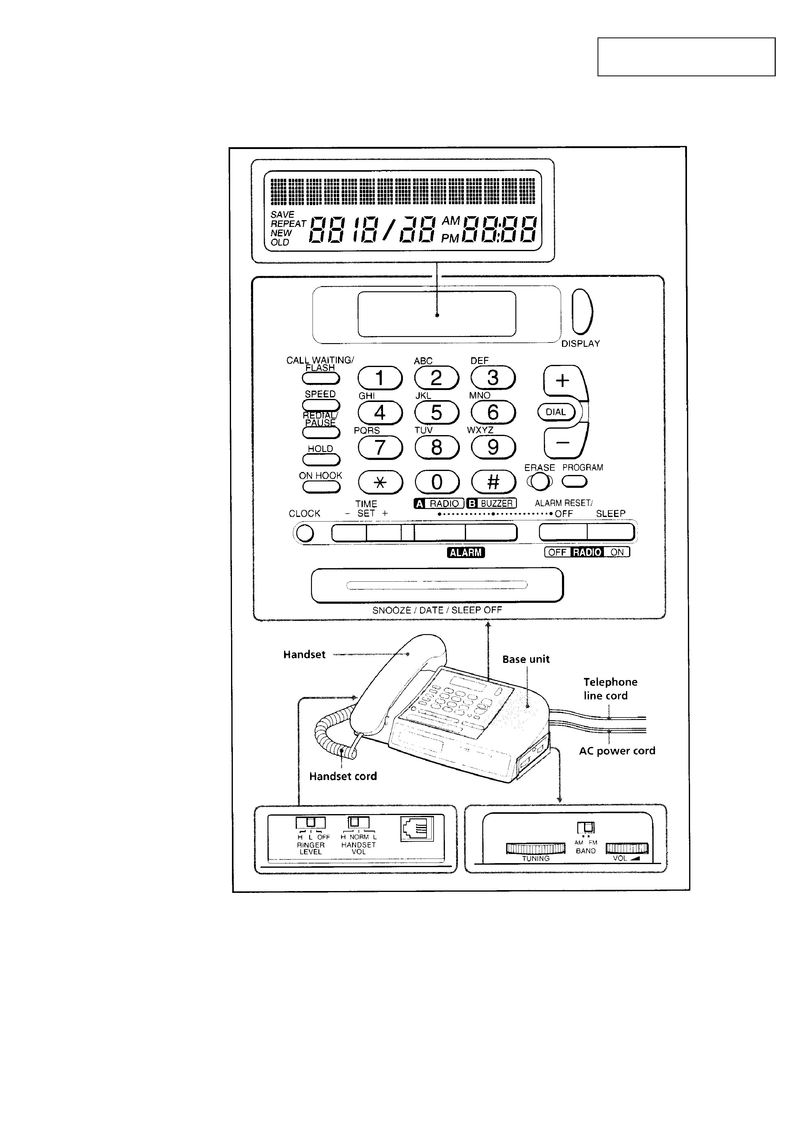
SECTION 1
GENERAL
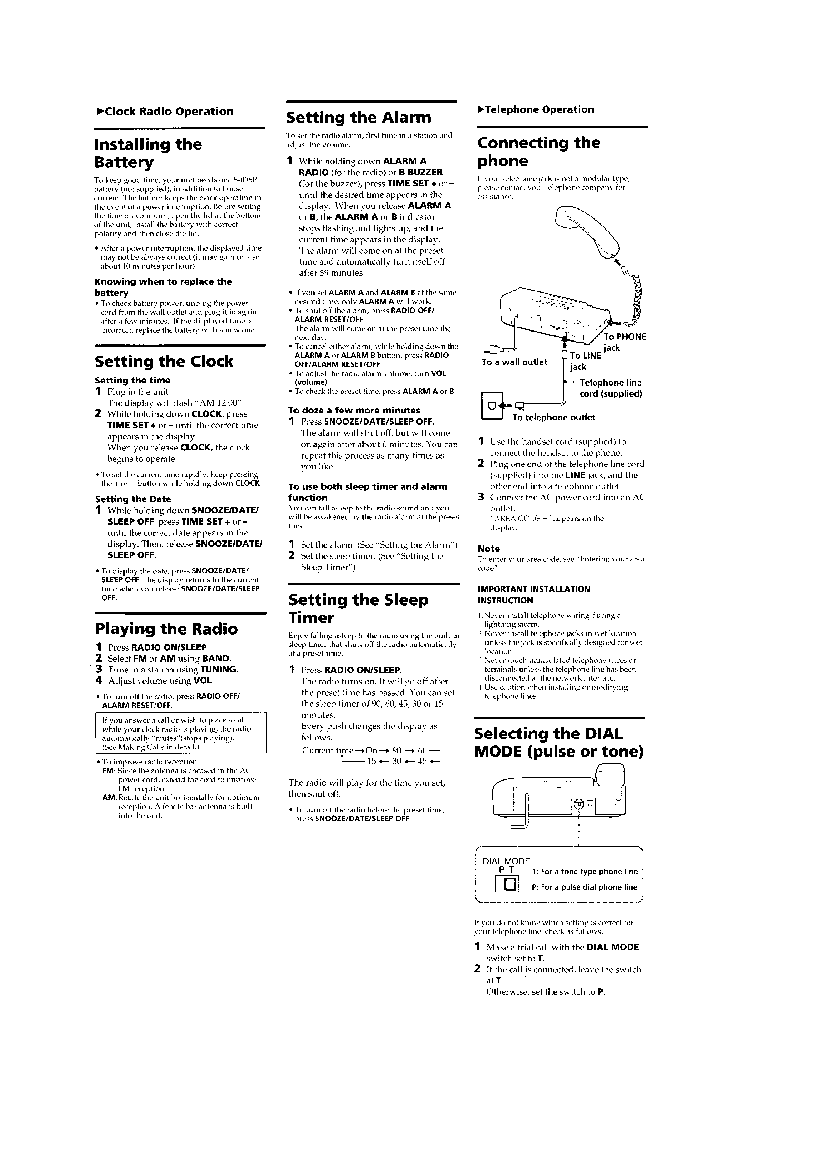
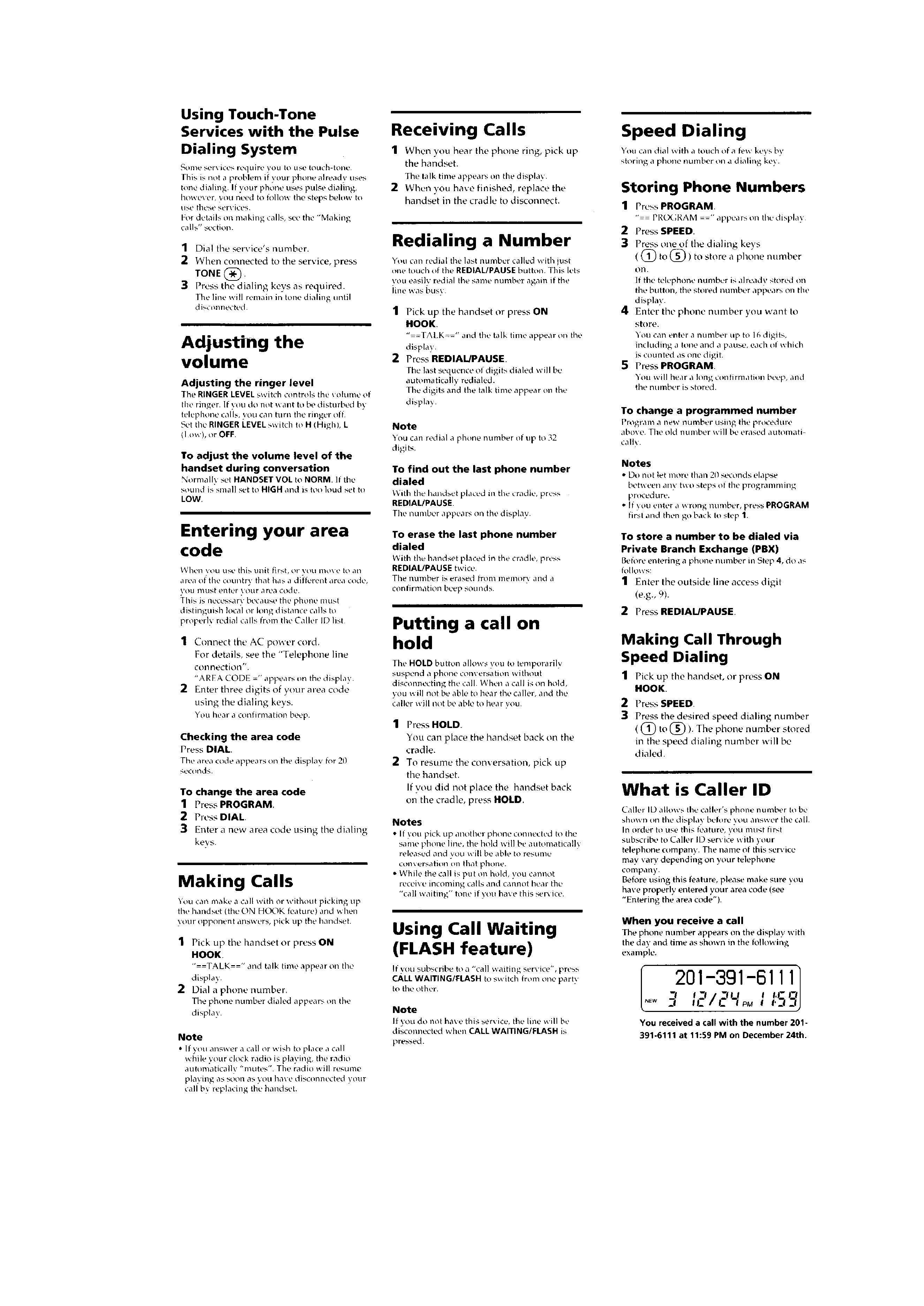
LOCATION AND FUNCTION OF CONTROLS
This section is extracted from
instruction manual.
TONE
OPER
4
5