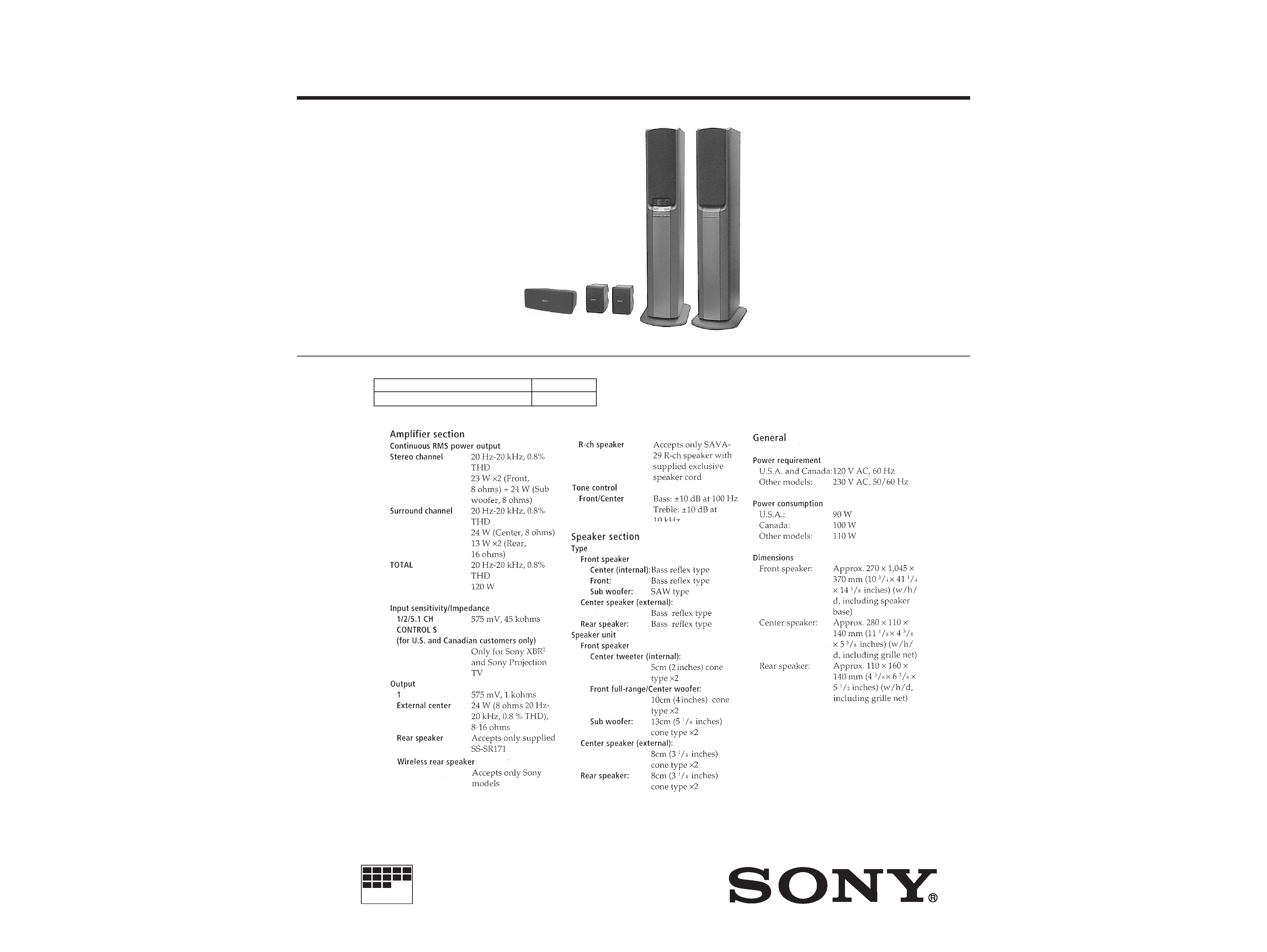
SAVA-29
US Model
Canadian Model
E Model
SERVICE MANUAL
HOME THEATER ACTIVE SPEAKER SYSTEM
MICROFILM
-- Continued on next page --
SPECIFICATIONS
(Center)
(Rear)
(L-ch)
(R-ch)
This unit is composed of the front speaker and the following units.
REAR SPEAKER
EXTERNAL CENTER SPEAKER
SS-SR171
SS-CN15AV
-- 2 --
TABLE OF CONTENTS
SAFETY-RELATED COMPONENT WARNING!!
COMPONENTS IDENTIFIED BY MARK
! OR DOTTED LINE WITH
MARK
! ON THE SCHEMATIC DIAGRAMS AND IN THE PARTS
LIST ARE CRITICAL TO SAFE OPERATION. REPLACE THESE
COMPONENTS WITH SONY PARTS WHOSE PART NUMBERS
APPEAR AS SHOWN IN THIS MANUAL OR IN SUPPLEMENTS
PUBLISHED BY SONY.
ATTENTION AU COMPOSANT AYANT RAPPORT
À LA SÉCURITÉ!
LES COMPOSANTS IDENTIFÉS PAR UNE MARQUE
! SUR LES
DIAGRAMMES SCHÉMATIQUES ET LA LISTE DES PIÈCES SONT
CRITIQUES POUR LA SÉCURITÉ DE FONCTIONNEMENT. NE
REMPLACER CES COMPOSANTS QUE PAR DES PIÈSES SONY
DONT LES NUMÉROS SONT DONNÉS DANS CE MANUEL OU
DANS LES SUPPÉMENTS PUBLIÉS PAR SONY.
TEST MODE ······································································ 3
1. GENERAL ·········································································· 4
2. DISASSEMBLY
2-1.
Removal Amplifier Block ··················································· 5
3. DIAGRAMS
3-1.
Circuit Boards Location ····················································· 6
3-2.
Schematic Diagram --Dolby Section -- ··························· 7
3-3.
Printed Wiring Board --Dolby Section -- ························· 9
3-4.
Schematic Diagram --Display Section -- ······················· 11
3-5.
Printed Wiring Board --Display Section -- ···················· 13
3-6.
Schematic Diagram --Power Section -- ························· 15
3-7.
Printed Wiring Board --Power Section -- ······················ 17
3-8.
Schematic Diagram --Power Transformer Section -- ···· 19
3-9.
Printed Wiring Board --Power Transformer Section -- ·· 21
3-10. Printed Wiring Board --Main Section -- ························ 23
3-11. Schematic Diagram--Main Section (1/2) -- ··················· 25
3-12. Schematic Diagram --Main Section (2/2) -- ················· 27
3-13. IC Pin Function ································································ 29
3-14. IC Block Diagrams ··························································· 30
4. EXPLODED VIEWS
4-1.
System (L) Assy ······························································· 32
4-2.
System (R) Assy ······························································· 33
4-3.
Amplifier Section ····························································· 34
4-4.
Rear Speaker Section ························································ 35
4-5.
Center Speaker Section ···················································· 36
5. ELECTRICAL PARTS LIST ······································· 37
After correcting the original service problem, perform the
following safety checks before releasing the set to the customer:
Check the antenna terminals, metal trim, "metallized" knobs, screws,
and all other exposed metal parts for AC leakage. Check leakage as
described below.
LEAKAGE
The AC leakage from any exposed metal part to earth ground and
from all exposed metal parts to any exposed metal part having a
return to chassis, must not exceed 0.5 mA (500 microampers).
Leakage current can be measured by any one of three methods.
1.
A commercial leakage tester, such as the Simpson 229 or RCA
WT-540A. Follow the manufacturers' instructions to use these
instruments.
2.
A battery-operated AC milliammeter. The Data Precision 245
digital multimeter is suitable for this job.
3.
Measuring the voltage drop across a resistor by means of a
VOM or battery-operated AC voltmeter. The "limit" indication
is 0.75 V, so analog meters must have an accurate low-voltage
scale. The Simpson 250 and Sanwa SH-63Trd are examples of
a passive VOM that is suitable. Nearly all battery operated
digital multimeters that have a 2V AC range are suitable. (See
Fig. A)
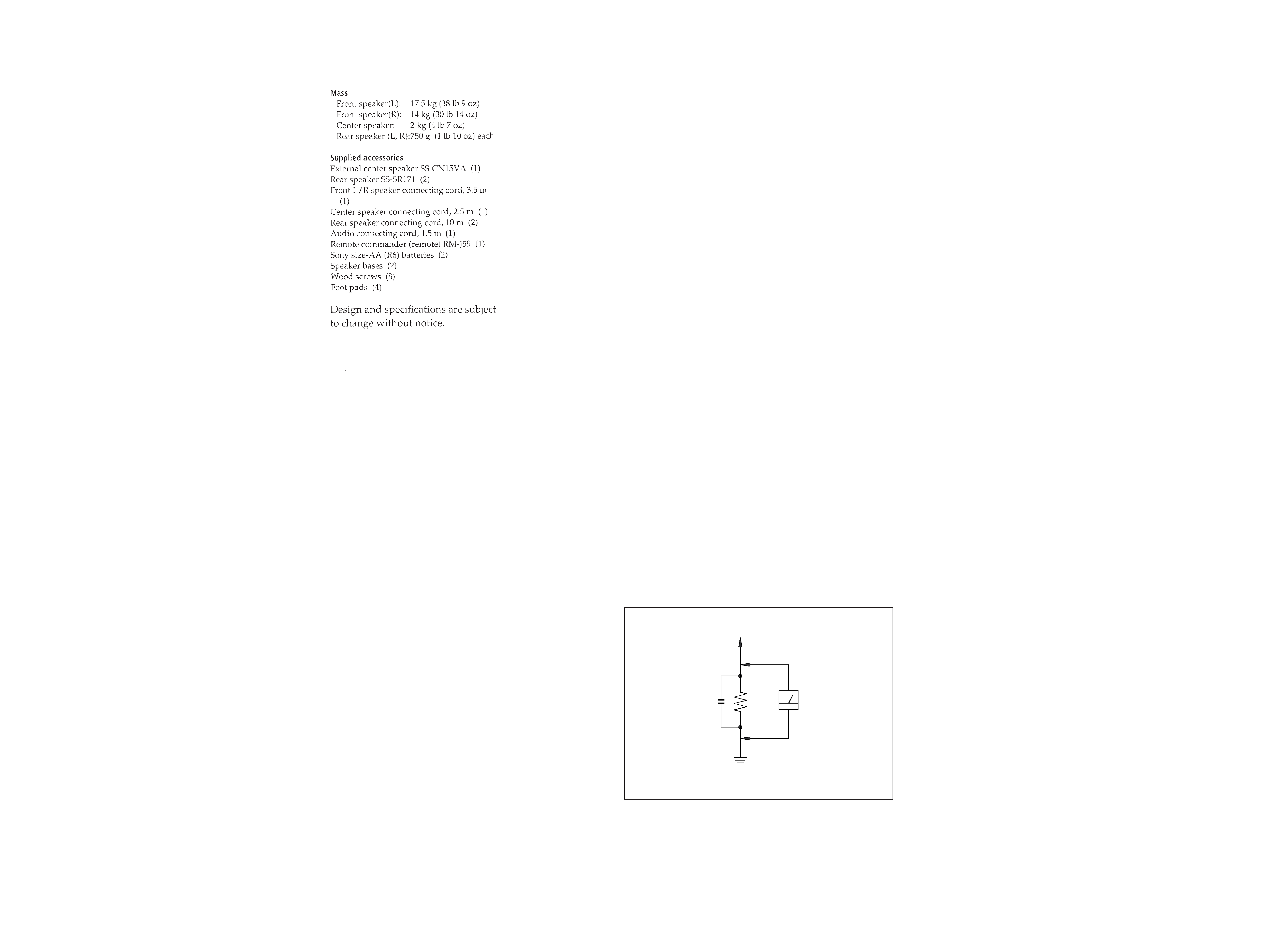
SAFETY CHECK-OUT
To Exposed Metal
Parts on Set
0.15
µF
1.5k
AC
voltmeter
(0.75V)
Earth Ground
Fig. A. Using an AC voltmeter to check AC leakage.
-- 3 --
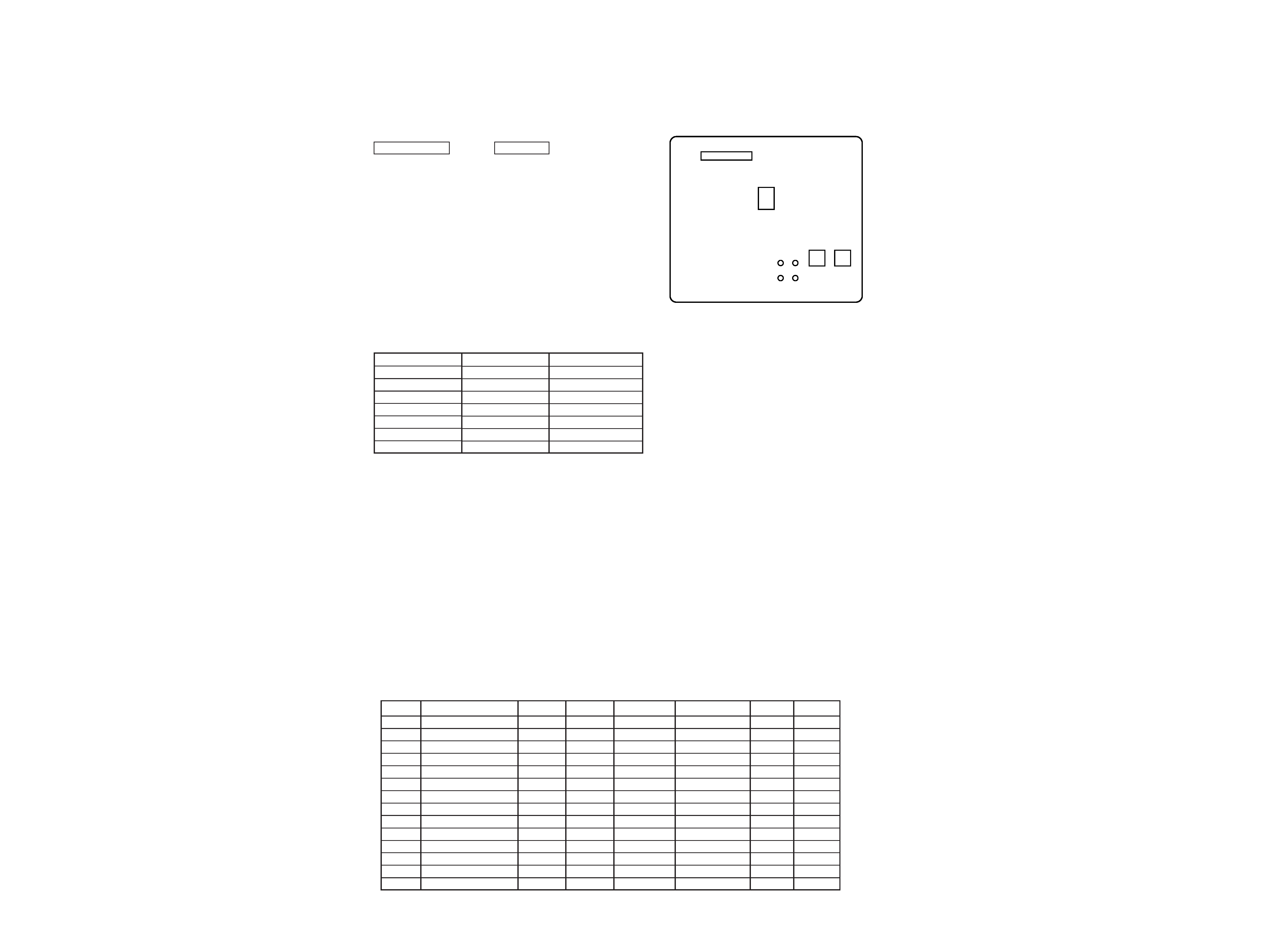
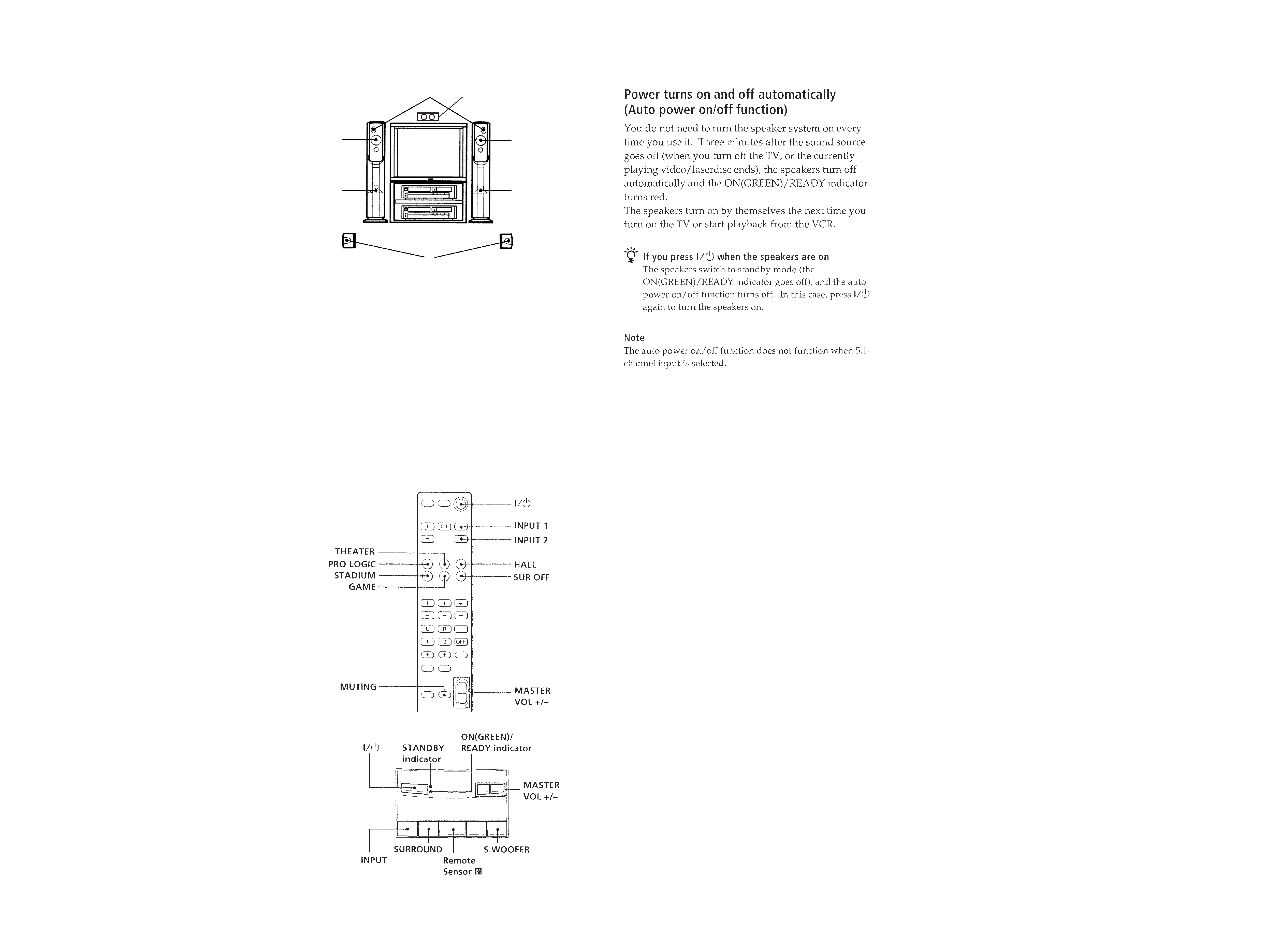
TEST MODE
MODE ALL FLUORESCENT INDICATOR TUBES
LIGHT
When the AC plug is inserted to the power outlet with pressing the
MASTER VOL + button and S.WOOFER button displayed model
name, after the all fluorescent indicator tubes light.
KEY CHECK MODE
1. Pull out the AC plug from the power outlet and turn the power
OFF.
2. Connect the lead wire to TP3 and TP4 on the KEY board.
3. Insert the AC plug to the power outlet and set to STANDBY
mode.
4. Let the lead wire short TP3 and TP4.
5. Fluorescent indicator tube displayed "KEY CHK 29" , and enter
the key check mode.
6. Pressing any buttons, the number of button will be displayed on
the fluorescent indicator tube.
7. After all buttons are pressed, it will be in the STANDBY mode.
Note:
1. The LED (D505)lights while pressing each button.
The LED lights in red when even number of buttons are pressed,
and it lights in green when odd number of buttons are pressed.
2. The LED lights even when the pressed button is pressed again.
CN552
IC513
TP2 TP4
TP1 TP3
S505
S506
Button
I / u
MASTER VOL
MASTER VOL +
INPUT
SURROUND
CENTER MODE
S.WOOFER
Button Number
1
2
3
4
5
6
7
LED Color
Red
Green
Red
Green
Red
Green
Red
AMP CHECK MODE
1. Pull out the AC plug from the power outlet and turn the power
OFF.
2. Connect the lead wire to TP1 and TP2 on the KEY board.
3. Insert the AC plug to the power outlet and set to STANDBY
mode.
4. Let the lead wire connected TP1 and TP2.
5. Fluorescent indicator tube displayed "AMP CHK 29" or "AMP
CHK 59", and enter the amp check mode.
6. The chek step advances in order as TP1 and TP2 are shorted.
7. To exit the test mode, disconnect the AC plug from power outlet.
AMP CHK 29 or 59
AMP CHK 1
AMP CHK 2
AMP CHK 3
AMP CHK 4
AMP CHK 5
AMP CHK 6
AMP CHK 7
AMP CHK 8
AMP CHK 9
AMP CHK 10
AMP CHK 11
AMP CHK 12
AMP CHK 13
STEP
0
1
2
3
4
5
6
7
8
9
10
11
12
13
INPUT
1
1
1
1
1
1
1
1
1
1
2
2
5.1
2
SW MODE
1
OFF
OFF
OFF
OFF
OFF
OFF
OFF
1
2
1
1
1
1
SUR MODE
PRO LOGIC
OFF
OFF
OFF
PRO LOGIC
PRO LOGIC
PRO LOGIC
GAME
OFF
OFF
PRO LOGIC
PRO LOGIC
PRO LOGIC
BASS
0
0
5
+5
5
+5
0
0
0
0
0
0
0
0
TREBLE
0
0
5
+5
5
+5
0
0
0
0
0
0
0
0
· Parts Location
[KEY BOARD] -- SOLDELING side --
VOL
MIN
MAX
MAX
MAX
MAX
MAX
MAX
MAX
MIN
MAX
MAX
MAX
MAX
MAX
* The step 13 is the AUTO POWER ON/OFF check.
*
-- 4 --
SECTION 1
GENERAL
1 LEFT CHANNEL SPEAKER/CENTER
CHANNEL WOOFER
2 CENTER CHANNEL TWEETERS
3 RIGHT CHANNEL SPEAKER/CENTER
CHANNEL WOOFER
4 SUPER WOOFER
5 REAR SPEAKER
6 EXTERNAL CENTER SPEAKER
1
2
3
4
4
5
2
6
REMOTE COMMANDER
FRONT SPEAKER (L-CH)
SAVA-29
-- 6 --
-- 5 --
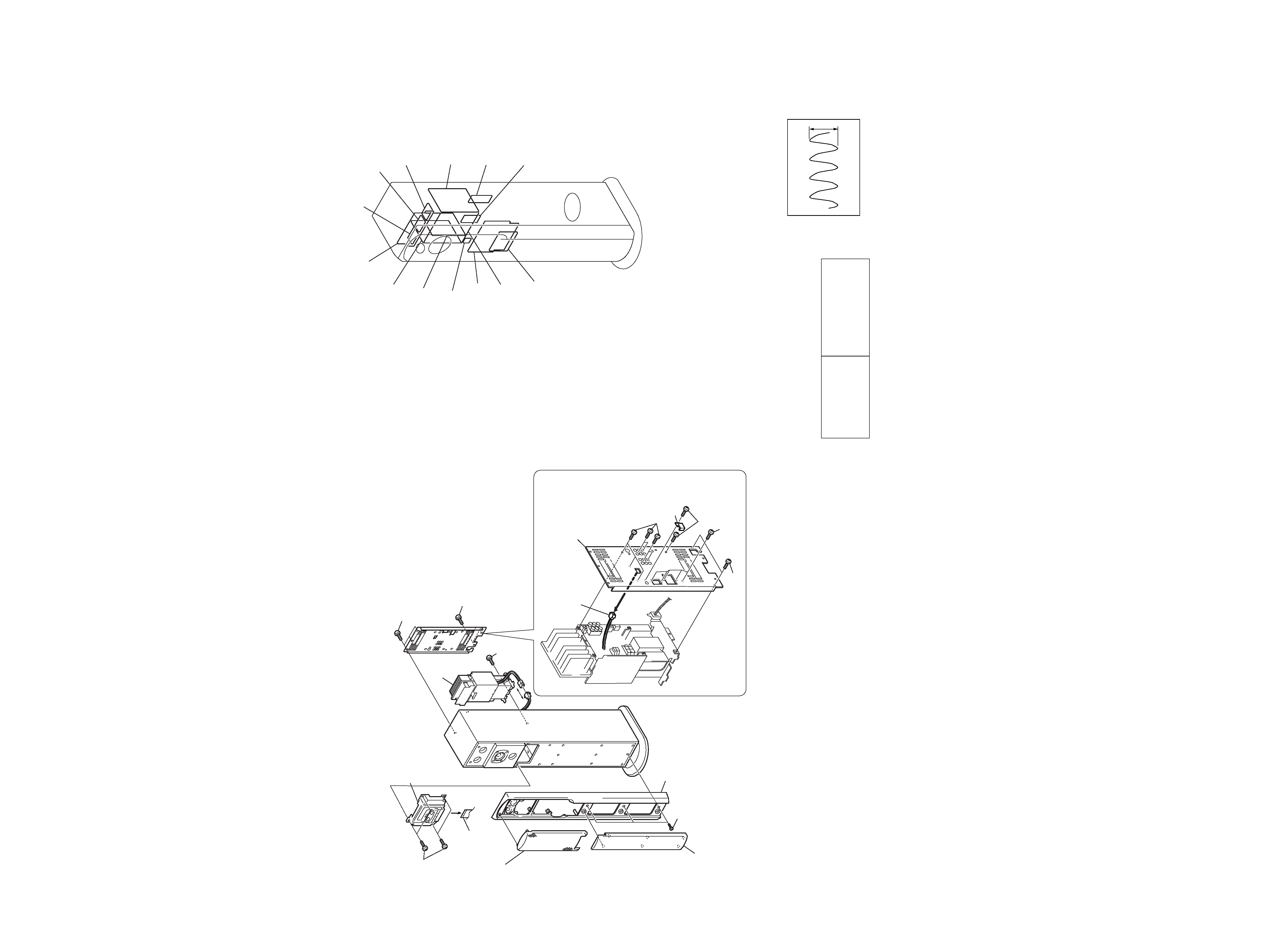
SECTION 2
DISASSEMBLY
SECTION 3
DIAGRAM
3-1. CIRCUIT BOARDS LOCATION
· Waveforms
For schematic diagrams.
Note:
· All capacitors are in µF unless otherwise noted. pF: µµF
50 WV or less are not indicated except for electrolytics
and tantalums.
· All resistors are in
and 1/4 W or less unless otherwise
specified.
·
%
: indicates tolerance.
·
¢
: internal component.
· 2 : nonflammable resistor.
· 1 : fusible resistor.
· C : panel designation.
· U : B+ Line.
· V : B Line.
· Voltages and waveforms are dc with respect to ground
under no-signal (detuned) conditions.
· Voltages are taken with a VOM (Input impedance 10 M
).
Voltage variations may be noted due to normal production
tolerances.
· Waveforms are taken with a oscilloscope.
· Circled numbers refer to waveforms.
THIS NOTE IS COMMON FOR PRINTED WIRING
BOARDS AND SCHEMATIC DIAGRAMS.
(In addition to this necessary note is printed in each
block.)
Note:
The components identified
by mark
! or dotted line with
mark
! are critical for safety.
Replace only with part
number specified.
Note:
Les composants identifiés par une
marque
! sont critiques pour la
sécurité.
Ne les remplacer que par une
piéce portant le numéro spécifié.
· Signal path.
F
: AUDIO
· Abbreviation
CND : Canadian
SP
: Singapore
MY
: Malaysia
For printed wiring boards.
Note:
· X : parts extracted from the component side.
· b : Pattern from the side which enables seeing.
2 IC501# (X2)
5.0 MHz
5.6Vp-p
4 Front panel assy
7 Display panel assy
6 Flat type wire
5 Four screws
(4
× 20)
1 Grill frame assy
2 Ornament frame
3 Three screws
(4
× 20)
!·
!¶ Screw
(M4
× 16)
9 Two screws
(M4
× 16)
8 Three screws
(4
× 25)
!ª Amplifier
! Connector
!§ Back panel
!º Seven screws
(+BVTP 3
× 8)
!¡ Two screws
(+BVTP 3
× 8)
!£ Five screws
(+BVTP 3
× 8)
!¢ Two screws
(M4
× 16)
!TM
POWER board
PS board
MAIN board
KEY board
DOLBY board
DISPLAY board
REG board
INPUT board
POW-SR board
T2 board
T1 board
POW-CSW board
POW-LR board
2-1. REMOVAL AMPLIFIER BLOCK (FRONT SPEAKER: L-CH)