Sony Corporation
2001
SA-F21
3-071-506-11 (3)
Active Speaker
System
Operating Instructions
Mode d`emploi
English
Playing the Disc (fig. D)
After connecting and setting up the player, you
can play the disc.
1 Turn on the components.
TV:
Turn on the TV and switch the input selector
on the TV to the player.
Player:
Turn on the player.
2 Press ?/1 (power) on the subwoofer.
The subwoofer is turned on and the power
indicator changes from red (standby) to
green.
3 Press MODE on the subwoofer repeatedly
until the MASTER VOL indicator lights up
in green.
4 Press LEVEL to turn down the volume to
the minimum.
5 Insert the disc in the player.
6 Press H on the player.
Playback starts. Adjust the volume with
LEVEL +/ on the subwoofer.
Using the headphones
Connect the headphones (not supplied) to the
HEADPHONES jack on the subwoofer.
To adjust the volume, press MODE on the
subwoofer repeatedly until the MASTER VOL
indicator lights up. Then press LEVEL +/.
z
The subwoofer automatically enters
standby mode (Auto Power On/Off function)
If no audio signal is input to the subwoofer for about 3
minutes, the subwoofer automatically enters standby
mode and the ?/1 (power) indicator changes to red.
When an audio signal is input, the subwoofer turns on
automatically and the ?/1 indicator changes to green.
The Auto Power On/Off function works only when no
audio signal is input for about 3 minutes. If you want to
turn off the subwoofer at once, press ?/1 (power) on the
subwoofer.
Adjusting the speakers
To select the volume to be adjusted
1 Press MODE repeatedly to turn on the
desired volume indicator (MASTER VOL for
entire volume or SW VOL for subwoofer
volume).
2 Press LEVEL +/ to adjust the volume.
If you are using the DVP-F21
If you set the TV/DVD switch on the remote to
DVD, you can adjust the entire volume with VOL
+/ on the remote.
z Some of the remote that can control Sony AV
amplifiers (receivers) may be able to control the
volume of this system.
To select a range to be adjusted
1 Press MODE repeatedly to turn on the
desired range indicator (BASS for the low
frequency range or TREBLE for the middle to
high frequency range).
2 Press LEVEL +/ to adjust the volume.
To switch the subwoofer mode to match
the bass output of the sound source
Press LEVEL + and at the same time on the
subwoofer to switch the subwoofer mode
between MOVIE and MUSIC. The color of the SW
VOL indicator will indicate the current mode.
The default setting is MOVIE.
Mode
Color
For sound sources such as
MOVIE
Green
Movies
MUSIC
Red
Music
To return the volume setting to the default
setting
While pressing LEVEL + and at the same time,
press ?/1 (power) on the subwoofer.
Specifications
AUDIO POWER SPECIFICATIONS
POWER OUTPUT AND TOTAL HARMONIC
DISTORTION:
With 4 ohm loads, both channels driven, from 40
20000 Hz; rated 12 watts per channel minimum
RMS power, with no more than 1 % total
harmonic distortion from 200 milli watts to rated
output.
Satellite speakers (SS-MS21)
Speaker system
Full range, antimagnetic
speaker
Speaker unit
8 cm (
3 1/4 in.), cone type
Enclosure type
Bass reflex
Rated impedance
4 ohms
Power handling capacity
Maximum input power
30 W
Sensitivity level
79 dB (1 W, 1 m)
Frequency range
150 to 20,000 Hz
Dimensions (approx.)
90
× 200 × 64 mm (3 5/8 ×
7 7/8
× 2 5/8 in.) (w/h/d)
including projecting parts
Mass (approx.)
630 g (1 lb. 6 oz.)/piece
Subwoofer system (SA-WMS21)
Speaker system
Active subwoofer,
antimagnetic
Speaker unit
13 cm (
5 1/8 in.), cone type
woofer, dual voice coil
Enclosure type
Bass reflex
Reproduction frequency range
40 to 150 Hz
Power Output
Satellite speaker
15 W
× 2
Subwoofer
15 W + 15 W
Input jack
INPUT
Pin jack
Output jack
SPEAKER IMP 4
Speaker jack
HEADPHONES
Stereo mini jack
General
Power requirements
120 V AC, 60 Hz
Power consumption
55 W
Dimensions (approx.)
190
× 266 × 375 mm (7 1/2 ×
10 1/2
× 14 7/8 in.) (w/h/d)
including projecting parts
Mass (approx.)
7.0 kg (15 lb. 7 oz.)
Design and specifications are subject to change
without notice.
D
1
2
3
4
5
6
7
8
Parts and controls
1
?
/1 (power) button/indicator
2
MODE (mode) button
3
MASTER VOL (master volume) indicator
4
SW VOL (subwoofer volume) indicator
5
BASS (bass) indicator
6
TREBLE (treble) indicator
7
LEVEL (level) +/ buttons
8
HEADPHONES (headphones) jack
ENERGY STAR is a U.S. registered mark. As an
ENERGY STAR Partner, Sony Corporation has
determined that this product meets the
ENERGY
STAR guidelines for energy efficiency.
Troubleshooting Guide
If you experience any of the following difficulties
while using the system, use this troubleshooting
guide to help remedy the problem before
requesting repairs. Should any problem persist,
consult your nearest Sony dealer.
The subwoofer automatically entered
standby mode.
, Auto Power On/Off function worked because
no audio signal had been input for about 3
minutes.
There is no sound from the speakers.
, The system is not connected correctly.
, The system is connected by incorrect
connecting cords.
, The volume is turned down to the minimum.
, The headphones are connected.
Sound is noisy.
, The system is not connected correctly.
, Audio equipment or such is placed close to an
equipment causing noise such as TV.
, The plugs and jacks are dirty.
Sound stops suddenly.
, The system is not connected correctly.
, Short-circuit occurred to the stripped speaker
cord.
Pièces constitutives et commandes
1
?
/1 touche/témoin (alimentation)
2
Touche MODE (mode)
3
Témoin MASTER VOL (volume principal)
4
Témoin SW VOL (volume caisson de
graves)
5
Témoin BASS (graves)
6
Témoin TREBLE (aigus)
7
Touches LEVEL (niveau) +/
8
Prise HEADPHONES (casque)
Français
Lecture du disque (fig.
D)
Après raccordement et réglage du lecteur, vous
pouvez lire un disque.
1 Mettez les appareils sous tension.
Téléviseur :
Mettez le téléviseur sous tension et réglez le
sélecteur d'entrée sur TV vers le lecteur.
Lecteur :
Mettez le lecteur sous tension.
2 Appuyez sur ?/1 (alimentation) du caisson
de graves.
Le caisson de graves est sous tension et le
témoin d'alimentation passe du rouge (veille)
au vert.
3 Appuyez plusieurs fois sur MODE sur le
caisson de graves jusqu'à ce que le témoin
MASTER VOL s'allume en vert.
4 Appuyez sur LEVEL pour réduire le
volume au minimum.
5 Insérez le disque dans le lecteur.
6 Appuyez sur H sur le lecteur.
La lecture commence. Réglez le volume à
l'aide de LEVEL +/ sur le caisson de graves.
Utilisation du casque
Branchez le casque (non fourni) sur la prise
HEADPHONES du caisson de graves.
Pour régler le volume, appuyez plusieurs fois sur
MODE sur le caisson de graves jusqu'à ce que le
témoin MASTER VOL s'allume. Appuyez ensuite
sur LEVEL +/.
z
Le caisson de graves passe
automatiquement en mode de veille (fonction
Auto Power On/Off)
Si aucun signal audio n'est transmis au caisson de graves
pendant environ 3 minutes, celui-ci passe
automatiquement en mode de veille et le témoin ?/1
(alimentation) passe au rouge. Lorsqu'un signal audio est
entré, le caisson de graves se met automatiquement sous
tension et le témoin ?/1 passe au vert.
La fonction Auto Power On/Off n'est opérationnelle que
lorsque aucun signal audio n'est transmis pendant
environ 3 minutes. Si vous souhaitez mettre le caisson de
graves hors tension immédiatement, appuyez sur ?/1
(alimentation) sur le caisson de graves.
Réglages des enceintes
Pour sélectionner le volume à régler
1 Appuyez plusieurs fois sur MODE pour
mettre sous tension le témoin de volume
souhaité (MASTER VOL pour l'ensemble du
volume ou SW VOL pour le volume du
caisson de graves).
2 Appuyez sur LEVEL +/ pour régler le
volume.
Si vous utilisez le DVP-F21
Si vous réglez l'interrupteur TV/DVD de la
télécommande sur DVD, vous pouvez réglez
l'ensemble du volume avec VOL +/ sur la
télécommande.
z
Certaines télécommandes utilisées pour les
amplificateurs AV Sony (récepteurs) peuvent aussi
commander le volume de ce système.
Pour sélectionner une gamme à régler
1 Appuyez plusieurs fois sur MODE pour
allumer le témoin de gamme souhaité (BASS
pour la gamme des basses fréquences ou
TREBLE pour la gamme des moyennes et
hautes fréquences).
2 Appuyez sur LEVEL +/ pour régler le
volume.
Pour commuter le mode du caisson de
graves afin de correspondre à la sortie des
graves de la source audio
Appuyez en même temps sur LEVEL + et du
caisson de graves pour faire passer le mode du
caisson de graves de MOVIE à MUSIC. La
couleur du témoin SW VOL indique le mode
courant. La réglage par défaut est MOVIE.
Mode
Couleur
Pour les sources
sonores
telles que
MOVIE
Vert
Films
MUSIC
Rouge
Musique
Pour revenir au réglage par défaut du
volume
Tout en appuyant en même temps sur LEVEL + et
, appuyez sur ?/1 (alimentation) du caisson de
graves.
Spécifications
SPÉCIFICATIONS D'ALIMENTATION AUDIO
SORTIE D'ALIMENTATION ET DISTORSION
HARMONIQUE TOTALE :
Avec des charges de 4 Ohms, deux canaux actifs,
de 4020000 Hz ; une puissance RMS minimale de
12 Watts par canal, avec au maximum 1 % de
distorsion harmonique totale entre 200 milliwatts
et la sortie nominale.
Enceintes satellites (SS-MS21)
Type
Enceinte antimagnétique,
gamme complète
Unité d'enceinte
8 cm (3 1/4 pouces), en cône
Système acoustique Bass reflex
Impédance nominale 4 ohms
Productivité
Puissance maxi. d'entrée
30 W
Sensibilité
79 dB (1 W, 1 m)
Gamme de fréquences
150 à 20 000 Hz
Dimensions (approximatives)
90
× 200 × 64 mm (3 5/8 ×
7 7/8
× 2 5/8 pouces) (l/h/p)
parties saillantes comprises
Masse (approximative)
630 g (1 lb. 6 oz.)/unité
Caisson de graves (SA-WMS21)
Type
Caisson de graves actif,
antimagnétique
Unité d'enceinte
13 cm (5 1/8 pouces), caisson
de grave en cône, double
bobine mobile de haut-
parleur
Système acoustique Bass reflex
Gamme de fréquences de reproduction
40 à 150 Hz
Puissance de sortie
Enceinte satellite
15 W
× 2
Caisson de graves
15 W + 15 W
Prise d'entrée
INPUT
Prise à broches
Prise de sortie
SPEAKER IMP 4
Prise d'enceinte
HEADPHONES
Mini prise stéréo
Généralités
Puissance requise
120 V CA, 60 Hz
Consommation électrique
55 W
Dimensions (approximatives)
190
× 266 × 375 mm (7 1/2 ×
10 1/2
× 14 7/8 pouces) (l/h/
p) parties saillantes
comprises
Masse (approximative)
7,0 kg (15 lb. 7 oz.)
La conception et les spécifications sont sujettes à
modification sans préavis.
ENERGY STAR est une marque déposée aux
États-Unis. En sa qualité de partenaire
ENERGY
STAR, Sony Corporation considère que ce
produit répond aux directives de
ENERGY
STAR en termes d'efficacité énergétique.
Dépannage
Si vous rencontrez l'une des difficultés suivantes
pendant l'utilisation du système, utilisez ce guide
de dépannage pour remédier au problème avant
de réclamer une réparation. Si le problème
persiste, consultez votre revendeur Sony.
Le caisson de graves passe
automatiquement en mode de veille.
, La fonction Auto Power On/Off s'est
déclenchée car aucun signal audio n'a été reçu
pendant environ 3 minutes.
Aucun son ne sort des enceintes.
, Le système n'est pas raccordé correctement.
, Le système est raccordé à l'aide de câbles
inadaptés.
, Le volume est réduit au minimum.
, Le casque est branché.
Le son est parasité.
, Le système n'est pas raccordé correctement.
, Un équipement audio, par exemple, est placé
à proximité d'un appareil provoquant des
parasites, comme un téléviseur.
, Les fiches et les prises sont sales.
Le son s'arrête tout à coup.
, Le système n'est pas raccordé correctement.
, Un court-circuit s'est produit sur le câble
dénudé de l'enceinte.
Printed in China
English
Warning
To prevent fire or shock hazard, do not expose
the unit to rain or moisture.
This symbol is intended to alert the user
to the presence of uninsulated
"dangerous voltage" within the
product's enclosure that may be of
sufficient magnitude to constitute a risk
of electric shock to persons.
This symbol is intended to alert the user
to the presence of important operating
and maintenance (servicing) instructions
in the literature accompanying the
appliance.
For customers in the U.S.A.
Owner's Record
The model and serial numbers are located at the rear of
the unit. Record the serial number in the space provided
below. Refer to them whenever you call upon your Sony
dealer regarding this product.
Model No. SA-F21
Serial No.______________
NOTE:
This equipment has been tested and found to comply
with the limits for a Class B digital device, pursuant to
Part 15 of the FCC Rules. These limits are designed to
provide reasonable protection against harmful
interference in a residential installation. This equipment
generates, uses, and can radiate radio frequency energy
and, if not installed and used in accordance with the
instructions, may cause harmful interference to radio
communications. However, there is no guarantee that
interference will not occur in a particular installation. If
this equipment does cause harmful interference to radio
or television reception, which can be determined by
turning the equipment off and on, the user is
encouraged to try to correct the interference by one or
more of the following measures:
Reorient or relocate the receiving antenna.
Increase the separation between the equipment and
receiver.
Connect the equipment into an outlet on a circuit
different from that to which the receiver is connected.
Consult the dealer or an experienced radio/TV
technician for help.
CAUTION
You are cautioned that any changes or modifications not
expressly approved in this manual could void your
authority to operate this equipment.
For customers in Canada
CAUTION
TO PREVENT ELECTRIC SHOCK, DO NOT USE THIS
POLARIZED AC PLUG WITH AN EXTENSION CORD,
RECEPTACLE OR OTHER OUTLET UNLESS THE
BLADES CAN BE FULLY INSERTED TO PREVENT
BLADE EXPOSURE.
Precautions
On safety
Should any solid object or liquid fall into the cabinet,
unplug the speaker system and have it checked by
qualified personnel before operating it any further.
On power sources
· AC power cord must be changed only at the qualified
service shop.
· Before operating the speakers, check that the operating
voltage is identical with your local power supply. The
operating voltage is indicated on the nameplate on the
rear of the speakers.
· The unit is not disconnected from the AC power
source as long as it is connected to the wall outlet, even
if the unit itself has been turned off.
· If you are not going to use the speakers for a long time,
be sure to disconnect the speakers from the wall outlet.
To disconnect the AC power cord, grasp the plug itself;
never pull the cord.
On placement
· Do not install the appliance in a confined space, such
as a bookcase or built-in cabinet.
· Do not place the speakers near heat sources, or in a
place subject to direct sunlight, excessive dust or
mechanical shock.
· Good ventilation is essential to prevent internal heat
buildup. Place the speakers in a location with adequate
air circulation, and in a way that does not block the
rear ventilation holes.
On operation
· When turning on or off the subwoofer or other
equipment, lower the volume of the subwoofer to
minimum.
· To avoid damaging the subwoofer:
Be careful in setting the volume control of the
subwoofer to avoid an excessive input power.
Do not open the enclosure or remold speaker units
and networks.
The grill net is not removable. Do not remove it.
On the speaker system
Although this speaker system is magnetically shielded,
there may be cases where the picture on some TV sets
becomes magnetically distorted. In such a case, turn off
the power of the TV set once, and after 15 to 30 minutes
turn it on again.
If there seems to be no improvement, locate the
speaker system further away from the TV set. Also, be
sure not to place objects in which magnets are attached
or used near the speaker system, such as audio racks, TV
stands, and toys. These may cause magnetic distortion to
the picture due to their interaction with the system.
On cleaning
Clean the cabinet, panel and controls with a soft cloth
slightly moistened with a mild detergent solution. Do
not use any type of abrasive pad, scouring powder or
solvent such as alcohol or benzine.
If you have any question or problem concerning your
speaker system, please consult your nearest Sony dealer.
Setting Up
Step 1: Unpacking
Check that you have the following items:
·Audio cord (with red and white plugs) (1)
·Speaker cords (2.5 m) (2)
·Speaker stands (2)
·Stand screws (8)
·Washers for stand screws (8)
Step 2: Connecting Speakers
Before you start, turn off the power and
disconnect the power cord of each component.
Refer to the instructions supplied with the
components to be connected.
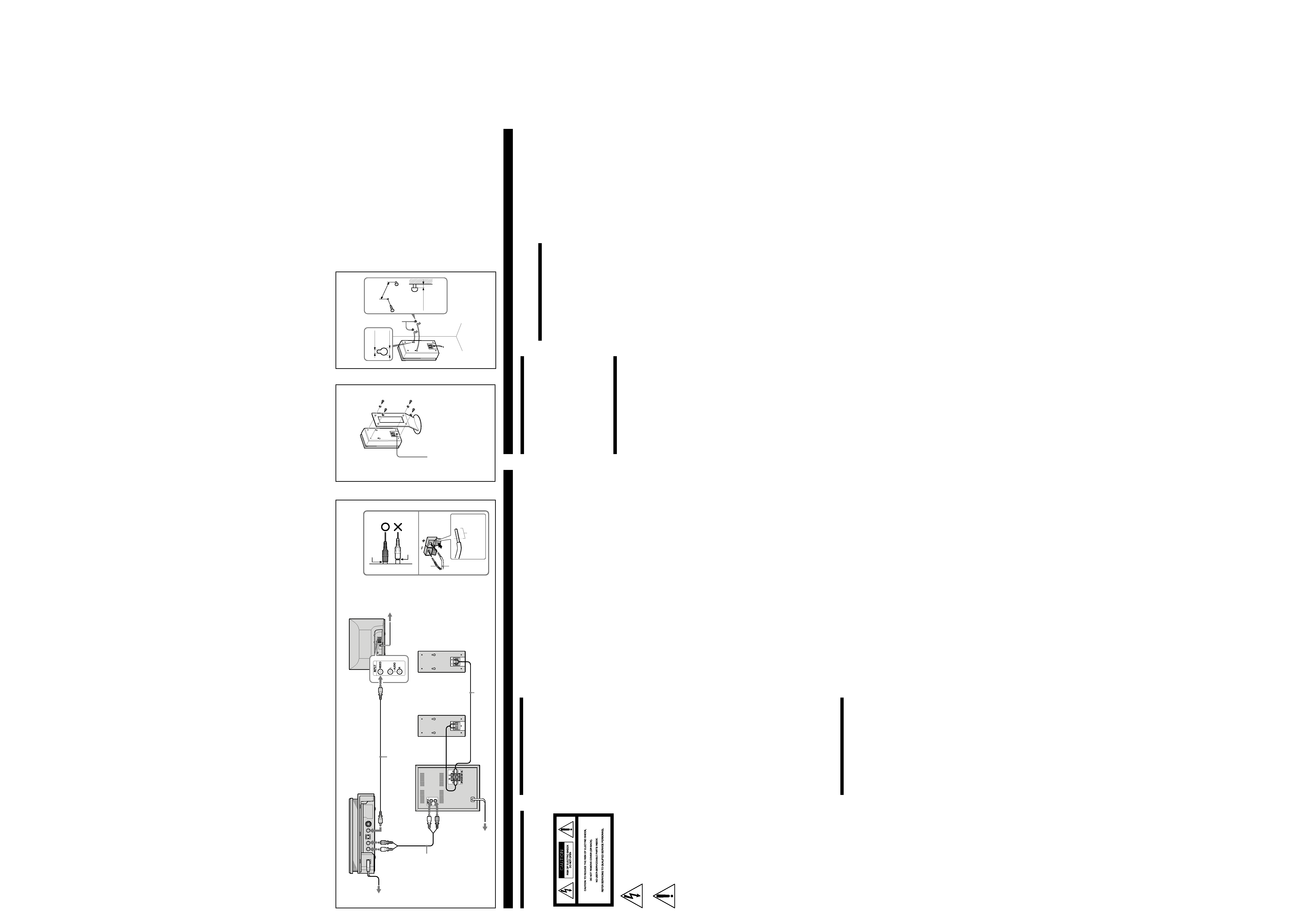
Connecting to the DVP-F21 (fig. A)
1 Connect the player to the TV.
Use a video cord (not supplied). First remove the
jack cover from the player, and then connect the
VIDEO OUT jack of the player with the video
input jack of the TV.
You can use the video/audio cord with red,
white and yellow plugs supplied with DVP-F21
instead of the video cord (not supplied). Connect
the yellow plug only.
If you connect a TV with S VIDEO input jack, use
an S VIDEO cord (not supplied). You will enjoy
high quality images.
2 Connect the player to the subwoofer.
Use the supplied audio cord (with red and white
plugs). Connect the AUDIO OUT L/R jacks of the
player to the INPUT L/R jacks of the subwoofer.
Connect the red plug to the red jack and white
plug to the white jack.
3 Connect the satellite speakers to the
subwoofer.
Use the supplied speaker cords. Connect the cord
with stripe to the # terminal.
Attach the jack cover to the player.
You can install the player in three ways;
horizontal, vertical or on the wall.
See "Step 3: Attaching the Jack Cover" in the
operating instructions supplied with the player.
Notes
· Plug cords securely to prevent unwanted noise. (fig.
A-1)
· Be sure to match the speaker cord to the appropriate
terminal: + to + and to . If the cords are reversed,
the sound will be distorted and will lack bass. (fig. A-
2)
Connecting to a component other than the
DVP-F21
Connect the SA-F21 in the same way as the DVP-
F21. Connect the audio output L/R (front L/R)
jacks of your player to the INPUT L/R jacks of
the subwoofer in step 2.
Step 3: Installing Speakers
For greater flexibility in the positioning of the
satellite speakers, use the supplied speaker
stands. (fig. B)
Speaker stands WS-FV10A, WS-TV10A, and WS-
WV10A are also available on option.
You can install the satellite speakers on the wall
using commercially available screws. (fig. C)
You need to determine the appropriate hanging
screws and/or other necessary hardware needed
to securely and safely fasten the speakers to the
wall. Please be sure you have selected fasteners
or screws that will fit in the hanging holes on the
rear of the speaker.
Placement of the screws should be at the same
height and should be 2 3/8 in. (59 mm) apart. The
screws or other fasteners should protrude by
3/16 in. to 7/32 in. (4 to 5 mm). You may also
mark placement of the screws or fasteners by use
of something like a template.
Hang the speakers on the screws and push the
speakers so that they fit against the wall.
Français
Avertissement
Pour prévenir tout risque d'incendie ou
d'électrocution, garder cet appareil à l'abri de
la pluie ou de l'humidité.
Pour les client au Canada
ATTENTION
POUR PREVENIR LES CHOCS ELECTRIQUES, NE PAS
UTILISER CETTE FICHE POLARISEE AVEC UN
PROLONGATEUR, UNE PRISE DE COURANT OU
UNE AUTRE SORTIE DE COURANT, SAUF SI LES
LAMES PEUVENT ETRE INSEREES A FOND SANS EN
LAISSER AUCUNE PARTIE A DECOUVERT.
Précautions
Sécurité
Si un objet ou du liquide pénètre à l'intérieur du boîtier,
débranchez le système acoustique et faites-le contrôler
par un personnel qualifié avant de le remettre en service.
Alimentation électrique
· Le cordon d'alimentation secteur ne peut être remplacé
que dans un centre de service après-vente qualifié.
· Avant de mettre les enceintes en service, vérifiez que la
tension de fonctionnement est identique à
l'alimentation secteur locale. La tension de
fonctionnement est indiquée sur la plaque signalétique
à l'arrière des enceintes.
· L'appareil n'est pas déconnecté de la source
d'alimentation secteur tant qu'il reste branché à la prise
murale, même si l'appareil proprement dit a été mis
hors tension.
· Si vous prévoyez de ne pas utiliser les enceintes
pendant une période prolongée, veillez à les
débrancher de la prise murale. Pour débrancher le
cordon d'alimentation secteur, ne tirez jamais sur le
cordon.
Installation
· N'installez pas l'appareil dans un espace confiné,
comme une bibliothèque ou un meuble encastré.
· N'installez pas les enceintes à proximité de sources de
chaleur ni à des endroits exposés au rayonnement
direct du soleil, à une poussière excessive ou à des
chocs mécaniques.
· Une bonne ventilation est essentielle pour empêcher
toute surchauffe interne. Installez les enceintes dans un
endroit bien ventilé et de manière à ne pas bloquer les
orifices de ventilation à l'arrière.
Fonctionnement
· Lors de la mise sous tension ou hors tension du caisson
de graves ou d'autres éléments, baissez le volume du
caisson de graves au minimum.
· Pour éviter d'endommager le caisson de graves :
Lors du réglage du volume du caisson de graves,
évitez une puissance d'entrée trop forte.
N'essayez pas d'ouvrir ou de recomposer les
enceintes ou les réseaux.
La grille n'est pas amovible. Ne la retirez pas.
Système acoustique
Bien que ce système soit magnétiquement blindé, il est
possible que l'image de certains téléviseurs soit
déformée. Dans ce cas, mettez le téléviseur hors tension,
puis remettez-le sous tension 15 à 30 minutes plus tard.
Si vous ne constatez pas d'amélioration, éloignez le
système du téléviseur. De même, n'utilisez pas et ne
posez pas d'objets dans lesquels sont fixés des aimants à
proximité du système, comme les racks audio, les
supports de téléviseurs et les jouets. En effet, ceci peut
provoquer une distorsion magnétique de l'image due à
leur interaction avec le système.
Nettoyage
Nettoyez le châssis, le panneau et les commandes à l'aide
d'un chiffon doux légèrement imbibé d'une solution
détergente douce. N'utilisez pas de tampons abrasifs, de
poudre à récurer ou de solvants tels que l'alcool ou la
benzine.
BC
A
2 3/8 in.
(59 mm)
Screws
Vis
#
3
TV
TV
Satellite speakers
Enceintes satellites
Subwoofer
Caisson de graves
CD/DVD Player DVP-F21
Notes
· When you install the speakers on the wall, make sure
that the wall is strong enough to hang the speakers.
· When you disconnect or connect the cords, take the
speakers down from the wall.
· For best possible surround sound, place the satellite
speakers on both sides of the TV or monitor equal
distances apart.
Step 4: Connecting the Power
Cord
Connect the power cord of each component to the
wall outlet.
Step 5: Setting Up for the CD/
DVD Player
You may need to make some setups for the
player. Refer to the instructions supplied with the
components to be connected.
If you are using the DVP-F21
When connecting to a wide screen TV, the image
may not fit your TV screen depending on the
disc. If you want to change the aspect ratio, select
"SCREEN SETUP" in the Setup Display and then
adjust the "TV TYPE"setting, see "Settings for the
Display (SCREEN SETUP)" in the operating
instructions supplied with the player.
A-1
A-2
1
2
3
3/16 7/32 in.
(4 5 mm)
Insert up to here.
Insérez jusqu'ici.
Video cord (not supplied)
Câble vidéo (non fourni)
Audio cord (supplied)
Câble audio (fourni)
Speaker cord (supplied)
Câble d'enceintes (fourni)
to AUDIO OUT L
vers AUDIO OUT L
to AUDIO OUT R
vers AUDIO OUT R
to VIDEO OUT/vers VIDEO OUT
Si vous avez des questions ou des problèmes à propos
de votre système, veuillez consulter votre revendeur
Sony le plus proche.
Installation
Étape 1 : déballage
Assurez-vous que vous disposez des éléments
suivants :
·Câble audio (avec fiches rouges et blanches) (1)
·Câbles d'enceintes (2,5 m) (2)
·Supports d'enceintes (2)
·Vis pour les supports (8)
·Rondelles pour les vis des supports (8)
Étape 2 : raccordement des
enceintes
Avant de commencer, mettez le système hors
tension et débranchez le câble d'alimentation de
chaque composant. Reportez-vous aux
instructions fournies avec les composants à
raccorder.
Raccordement au DVP-F21 (fig. A)
1 Raccordez le lecteur au téléviseur.
Utilisez un câble vidéo (non fourni). Retirez
d'abord la protection de la prise du lecteur, puis
raccordez la prise VIDEO OUT du lecteur à la
prise d'entrée vidéo du téléviseur.
Vous pouvez utiliser le câble vidéo/audio avec
les fiches rouges, blanches et jaunes fournies avec
le DVP-F21 à la place du câble vidéo (non fourni).
Raccordez la fiche jaune uniquement.
Si vous raccordez un téléviseur avec la prise
d'entrée S VIDEO, utilisez un câble S VIDEO
(non fourni). Vous obtiendrez des images de
haute qualité.
2 Raccordez le lecteur au caisson de graves.
Utilisez le câble audio fourni (avec les fiches
rouges et blanches). Raccordez les prises AUDIO
OUT L/R du lecteur aux prises INPUT L/R du
caisson de graves.
Raccordez la fiche rouge à la prise rouge et la
fiche blanche à la prise blanche.
3 Raccordez les enceintes satellites au
caisson de graves.
Utilisez les câbles d'enceintes fournis. Raccordez
le câble rayé à la borne #.
Fixez la protection de la prise au lecteur.
Vous pouvez installer le lecteur de trois façons :
horizontalement, verticalement ou sur une
cloison.
Reportez-vous à la section "Ètape 3: Mise en
place du couvercle de prises" dans le mode
d'emploi fourni avec le lecteur.
Remarques
· Branchez les câbles à fond pour éviter tout parasite
indésirable. (fig. A-1)
· Faites correspondre le fil de l'enceinte à la borne
appropriée : + avec + et - avec -. Si les fils sont inversés,
le son sera déformé et les graves seront insuffisants.
(fig. A-2)
Raccordement à un autre appareil que le
DVP-F21
Raccordez le SA-F21 de la même façon que le
DVP-F21. Raccordez les prises L/R (L/R avant)
de la sortie audio de votre lecteur aux prises
INPUT L/R du caisson de graves à l'étape 2.
Étape 3 : installations des
enceintes
Pour une plus grande liberté dans le
positionnement des enceintes satellites, utilisez
les supports d'enceintes fournis. (fig. B)
Les supports d'enceintes WS-FV10A, WS-TV10A
et WS-WV10A sont également disponibles en
option.
Vous pouvez fixer les enceintes satellites sur une
cloison à l'aide de vis disponibles dans le
commerce. (fig. C)
Pour fixer en toute sécurité les enceintes au mur,
vous devez définir quel type de vis de fixation et/
ou autres matériels sont nécessaires. Vérifiez que
vous avez choisi les attaches ou les vis
correspondant aux trous de fixation placés à
l'arrière de l'enceinte.
L'implantation des vis doit être horizontale et
elles doivent se trouver à 59 mm (2 3/8 pouces)
l'une de l'autre. Les vis ou autres types d'attache
doivent dépasser de 4 à 5 mm (3/16 à 7/32
pouces). Vous pouvez également marquer
l'implantation des vis ou des attaches à l'aide
d'un modèle.
Accrochez les enceintes sur les vis et poussez-les
pour les appuyer contre le mur.
Remarques
· Lorsque vous fixez les enceintes au mur, assurez-vous
que celui-ci est suffisamment résistant pour soutenir les
enceintes.
· Lorsque vous débranchez ou raccordez les cordons,
descendez les enceintes du mur.
· Pour obtenir le meilleur son surround possible, placez
les enceintes satellites de part et d'autre du téléviseur
ou du moniteur, à égale distance.
Étape 4 : raccordement du câble
d'alimentation
Raccordez le câble d'alimentation de chaque
composant à la prise murale.
Étape 5 : réglage pour le lecteur
CD/DVD
Il vous faudra peut-être procéder à quelques
réglages pour le lecteur. Reportez-vous aux
instructions fournies avec les composants à
raccorder.
Si vous utilisez le DVP-F21
En cas de raccordement à un téléviseur grand
écran, il se peut que l'image ne corresponde pas à
l'écran de votre téléviseur, en fonction du disque.
Si vous souhaitez modifier le rapport d'aspect,
sélectionnez "RÉGLAGE DE L'ECRAN" dans
l'écran d'installation, puis réglez "TYPE TÉLÉ" ;
reportez-vous à la section "Valeurs du menu
Display (RÉGLAGE DE L'ECRAN)" dans le mode
d'emploi fourni avec le lecteur.
Screw hole to attach the stand
such as WS-FV10A, WS-TV10A,
WS-WV10A (not supplied)
Trou de vis pour fixer un
support comme WS-FV10A, WS-
TV10A, WS-WV10A (non fourni)
3/16 in.
(4.5 mm)
3/8 in.
(9 mm)