MICROFILM
SERVICE MANUAL
RADIO CASSETTE-CORDER
E Model
Model Name Using Similar Mechanism
NEW
Tape Transport Mechanism Type
MF-W616-148
SPECIFICATIONS
CFS-616S
Ver 1.0 1999. 01
2
TABLE OF CONTENTS
1.
GENERAL ................................................................. 3
2.
DISASSEMBLY ......................................................... 4
3.
DIAL POINTER SETTING ..................................... 8
4.
MECHANICAL ADJUSTMENTS ....................... 9
5.
ELECTRICAL ADJUSTMENTS ......................... 9
Tape Deck Section ..........................................................
9
Tuner Section .................................................................. 10
6.
DIAGRAMS ................................................................. 13
6-1. Block Diagram TUNER Section ............................. 13
6-2. Block Diagram MAIN Section ................................ 15
6-3. Printed Wiring Board TUNER Section ................... 20
6-4. Schematic Diagram TUNER Section ....................... 21
6-5. Printed Wiring Boards MAIN Section .................... 24
6-6. Schematic Diagram MAIN Section ......................... 27
7.
EXPLODED VIEWS ................................................ 32
8.
ELECTRICAL PARTS LIST ............................... 42
SAFETY-RELATED COMPONENT WARNING!!
COMPONENTS IDENTIFIED BY MARK
! OR DOTTED
LINE WITH MARK
! ON THE SCHEMATIC DIAGRAMS
AND IN THE PARTS LIST ARE CRITICAL TO SAFE
OPERATION. REPLACE THESE COMPONENTS WITH
SONY PARTS WHOSE PART NUMBERS APPEAR AS
SHOWN IN THIS MANUAL OR IN SUPPLEMENTS PUB-
LISHED BY SONY.
Mark
Center frequency
red
10.70 MHz
blue
10.67 MHz
orange
10.73 MHz
black
10.64 MHz
white
10.76 MHz
HOW TO CHANGED THE CERAMIC FILTERS
This model is used two ceramic filters of CF1 and CF2.
You must used same type of color marked ceramic filters in order
to meet same specifications.
Therefore, the ceramic filter must changed two pieces together
since it's supply two pieces in one package as a spare parts.
CF1, 2
mark
3
SECTION 1
GENERAL
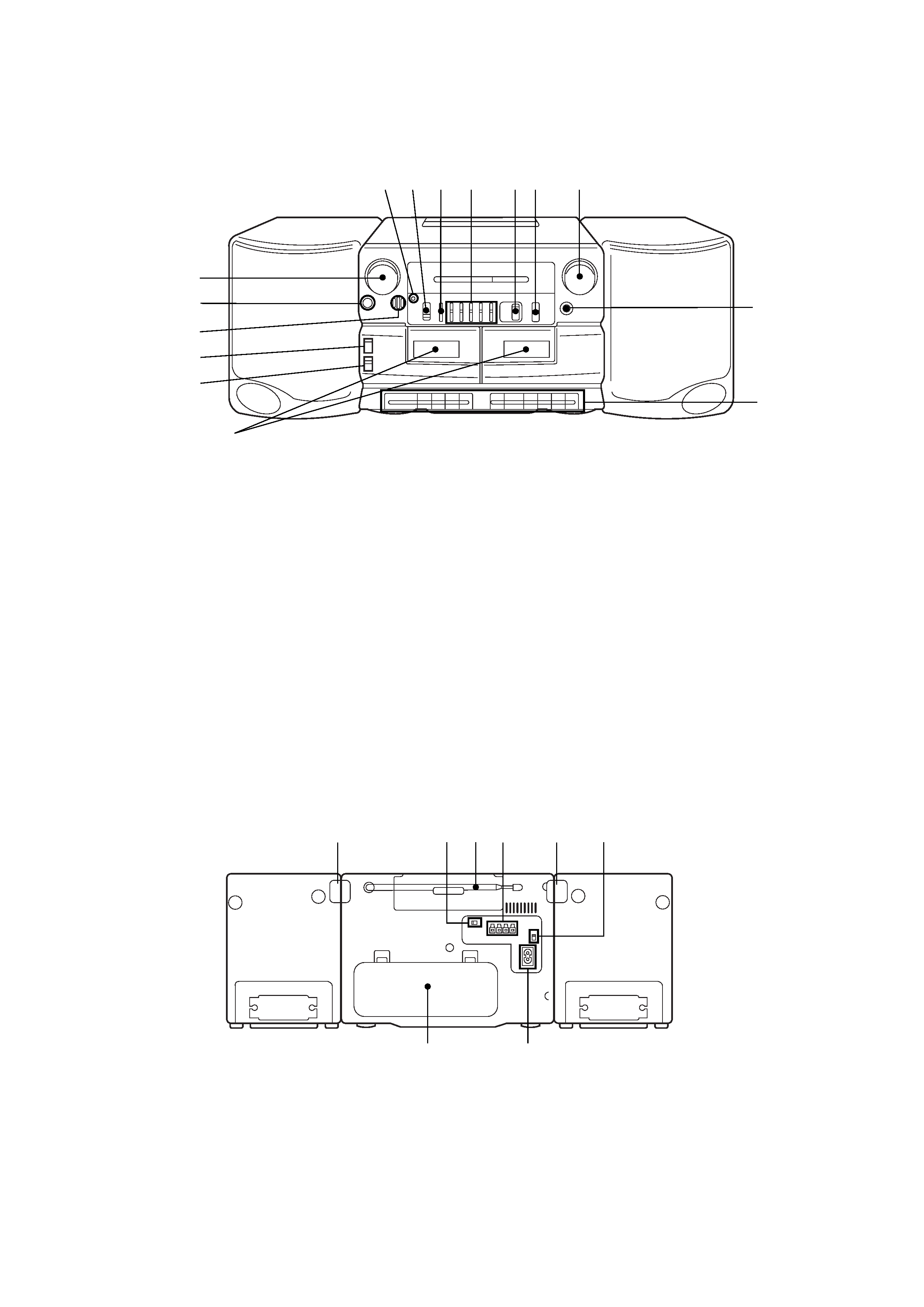
LOCATION OF CONTROLS
· Front view
1 Cassette compartments
2 DIRECTION switch
3 DIR MODE switch
4 MIC (microphone)
5 2 (PHONES (headphones)) jack (stereo mini-jack)
6 VOLUME knob
7 OPR/BATT (operation/battery) indicators
8 FUNCTION selector
RADIO
DUBBING HIGH
DUBBING NORM
TAPE/RADIO OFF
9 BALANCE control
0 5 BAND GRAPHIC EQUALIZER controls
!¡ PRESET MODE selector
!TM BAND selector
FM
SW1
SW2
MW
!£ TUNING knob
!¢ FINE TUNING knob
! Tape operating buttons
r
REC (record) button : Deck B only
( PLAY (playback) button
0 REW (rewind) button
) FF (fast-forward) button
p6 STOP/EJECT button
P
PAUSE button
1 LOCK tab (right side)
2 ISS switch
3 Telescopic aerial
4 SPEAKER terminals
5 LOCK tab (Left side)
6 VOLTAGE selector
7 /AC IN (AC power input) socket
8 Battery compartment
7 89
1
2
5
6
3
4
!
!£
0!¡!TM
!¢
· REAR view
56
7
8
12 3 4
4
CABINET (REAR) SECTION
BATT (/+) BOARD
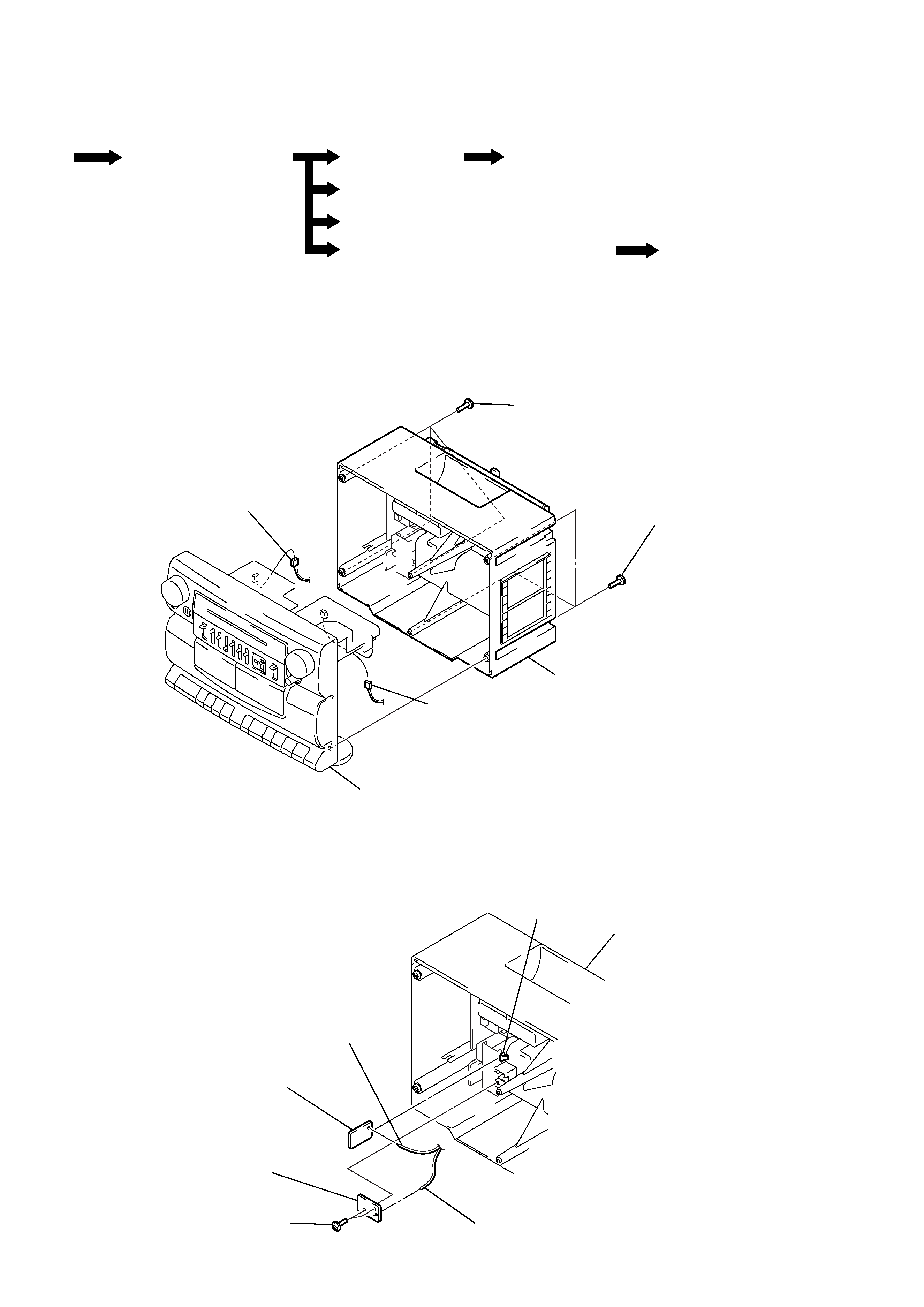
Note: Follow the disassembly procedure in the numerical order given.
SECTION 2
DISASSEMBLY
· This set can be disassembled in the order shown below.
SET
CABINET (REAR)SECTION
BATT (/+) BOARD
VOL/MAIN BOARD
TUNER BOARD
BELT, MOTOR
ASSY(W)(M901)
MECHANISM DECK SECTION (MF-W616-148),
REC SW BOARD
POWER (A/B) BOARD
cabinet (front) section
1 three screws
(BTP3
× 16)
1 three screws
(BTP3
× 16)
2 cabinet (rear) section
3 connector
(CNP307)
3 connector
(CNP1)
2 two screws
(BTP3
× 10)
3 BATT (-) board
5 BATT (+) board
4 claw
1 Remove the solder of lead.
6 Remove the solder of lead.
cabinet (rear) section
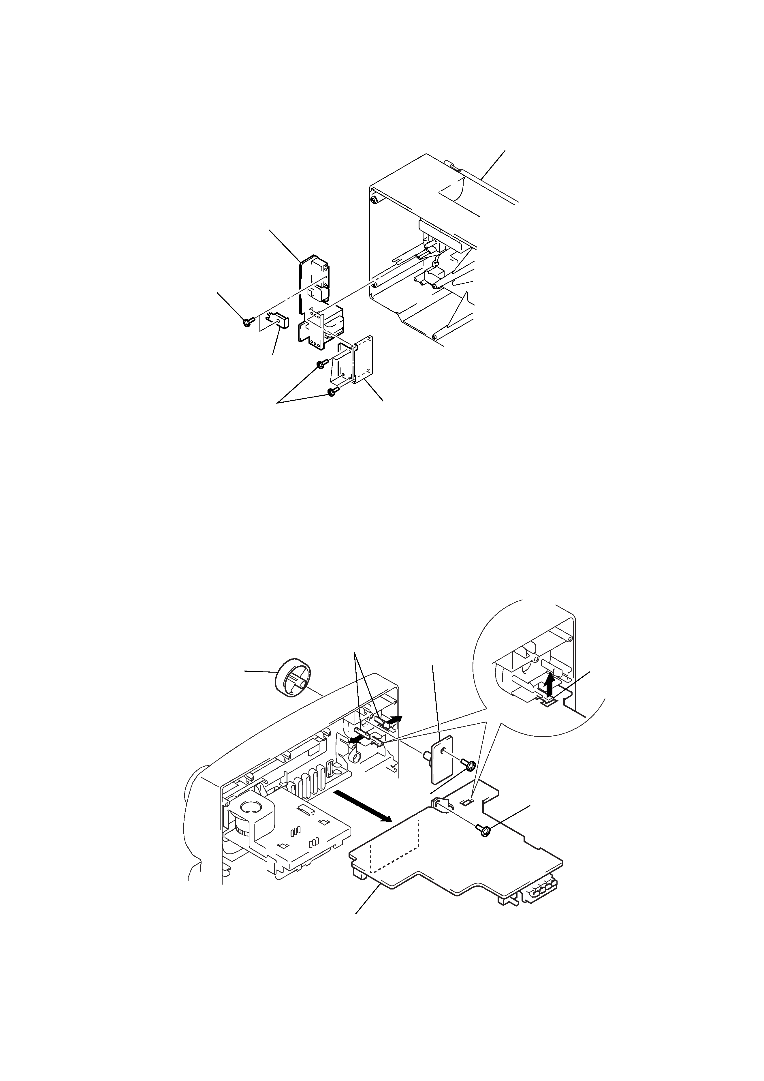
5
POWER (A/B) BOARD
VOL/MAIN BOARD
1 two screws
(BTP3
× 10)
3 six screws
(BTP3
× 10)
2 bracket (AC)
5 POWER (A/B) board
4 plate (T), shield
cabinet (rear) section
1 knob (VOL)
3 two claws
4 VOL board
2 two screws
(BTP3
× 10)
5 screw
(BTP3
× 10)
6 claw
7 MAIN board