Ver. 1.0
1998.07
MICROFILM
CFS-515L
SERVICE MANUAL
RADIO CASSETTE-CORDER
SPECIFICATIONS
East European Model
Model Name Using Similar Mechanism
NEW
Tape Transport Mechanism Type
MF-W495-117
Frequency range
FM : 65 108MHz
MW : 531 1,602kHz
LW : 153 279kHz
SW : 5.95 18MHz
IF
FM : 10.7MHz
MW/LW/SW : 455kHz
Aerials
FM/SW : Telescope
MW/LW : Built-in ferrite bar
Recording system
4-track, 2-channel stereo
Frequency response
70 13,000Hz
Speakers
Full range : 10cm (4 inches) dia., 6ohms,
cone type/Tweeter : 2cm (13/16 inches) dia.
Output
Headphones jack (stereo minijack), for
16 68 ohms impedance headphones
Maximum Power output
5W+5W
Battery life
FM Recording : Sony R20P : Approx. 10hours/
Sony LR20 alkaline : Approx. 20hours
Playback : Sony R20P : Approx. 3.5hours/
Sony LR20 alkaline : Approx. 8hours
Power requirements
230V AC, 50Hz
9V DC, six R20 (size D) batteries
Power consumption
AC 18 W
Dimensions
Approx. 697 x 211 x 201.5 mm (w/h/d)
(27 1/2 x 8 3/8 x 8 inches) incl. projecting parts and
controls, not incl. handle
Mass
Approx. 6.2 kg (13 lb 10 oz) incl. batteries
Supplied accessories
AC power cord (1)
Design and specifications are subject to change without notice.

2
Specifications ........................................................................... 1
1. GENERAL
Looking at the Controls ..................................................... 3
2. DISASSEMBLY
2-1. Cabinet (Front) Section,
Cabinet (Rear) Section ................................................ 4
2-2. BATT () Board, BATT (+) Board ............................. 4
2-3. Power (AC) Board, Power (DC) Board ...................... 4
2-4. Mechanism Deck, REC SW Board ............................. 5
2-5. Chassis Sub Assy, Belt ................................................ 5
2-6. VOL Board, Main Board, ECM Board ....................... 6
2-7. Tuner Board ................................................................ 6
3. DIAL POINTER INSTALLATION ............................ 7
4. ADJUSTMENTS
4-1. Mechanical Adjustments ............................................ 8
4-2. Electrical Adjustments ................................................ 8
5. DIAGRAMS
5-1. Block Diagram ........................................................... 11
5-2. Printed Wiring Boards Main Section .................. 14
5-3. Schematic Diagram Main Section ...................... 17
5-4. Printed Wiring Boards Tuner Section ................. 20
5-5. Schematic Diagram Tuner Section ..................... 21
6. EXPLODED VIEWS
6-1. Cabinet (Rear) Section .............................................. 25
6-2. Cabinet (Front) Section ............................................ 26
6-3. Mechanism Deck Section -1 ..................................... 27
6-4. Mechanism Deck Section -2 ..................................... 28
6-5. Speaker Section ........................................................ 29
7. ELECTRICAL PARTS LIST .................................... 30
SAFETY-RELATED COMPONENT WARNING!!
COMPONENTS IDENTIFIED BY MARK
! OR DOTTED LINE
WITH MARK
! ON THE SCHEMATIC DIAGRAMS AND IN THE
PARTS LIST ARE CRITICAL TO SAFE OPERATION.
REPLACE THESE COMPONENTS WITH SONY PARTS WHOSE
PART NUMBERS APPEAR AS SHOWN IN THIS MANUAL OR IN
SUPPLEMENTS PUBLISHED BY SONY.
TABLE OF CONTENTS
· HOW TO CHANGED THE CERAMIC FILTERS
This model is used two ceramic filters of CF1 and CF2.
You must used same type of color marked ceramic filters in
order to meet same specifications.
Therefore, the ceramic filter must changed two pieces together
since it's supply two pieces in one package as a spare parts.
Mark
Center fequency
red
blue
orange
10.70MHz
10.67MHz
10.73MHz
mark
CF1, 2
3
SECTION 1
GENERAL
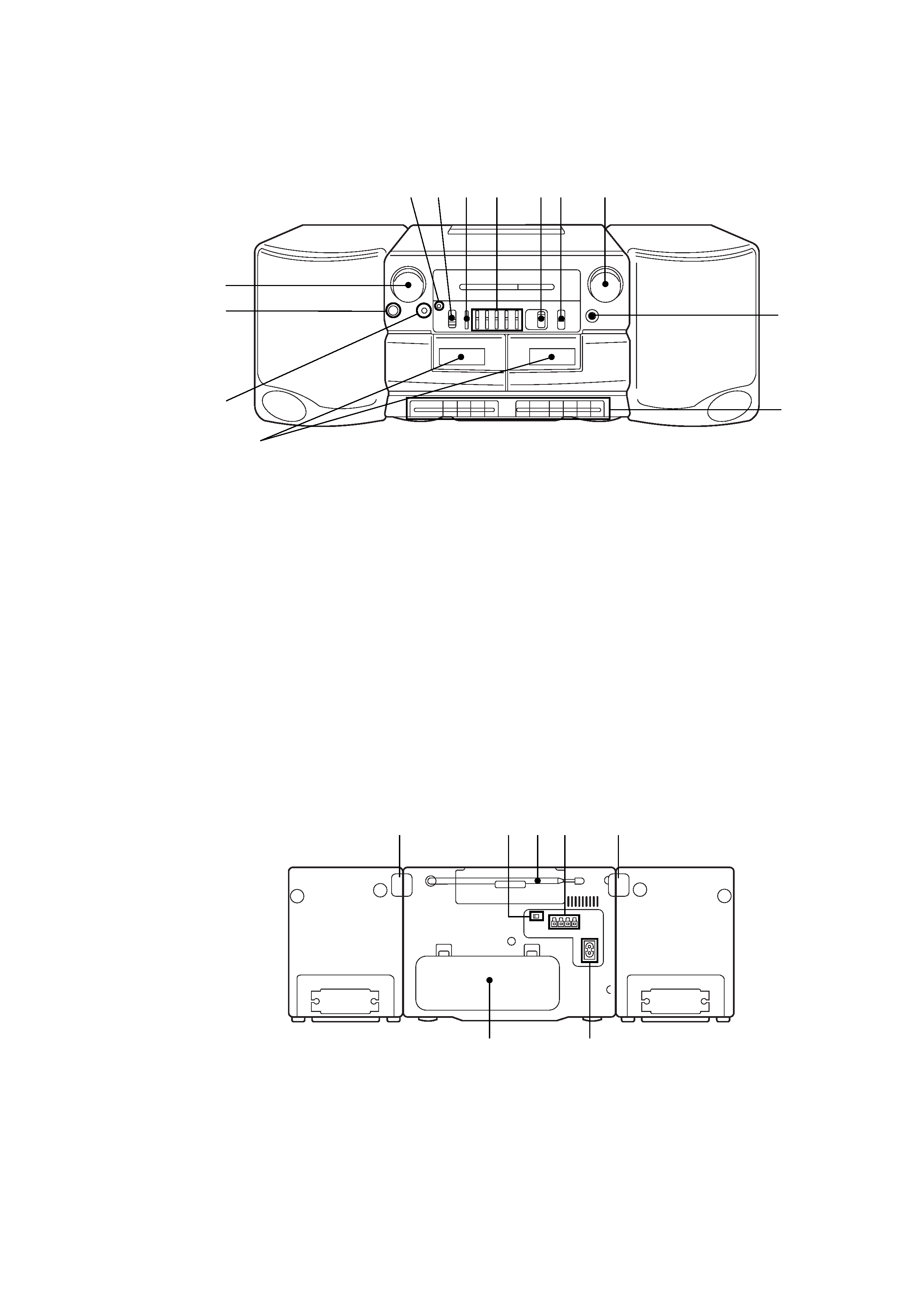
LOOKING AT THE CONTROLS
FRONT PANEL
REAR PANEL
5 67
1
2
3
4
!£
!¡
89!º
!TM
5
6
7
12 3 4
1 Cassette compartments
2 MIC (microphone)
3 PHONES (headphones) jack (stereo mini-jack)
4 VOLUME control
5 OPR/BATT (operation/battery) indicators
6 FUNCTION selector
RADIO
DUBBING HIGH
DUBBING NORM
TAPE/RADIO OFF
7 BALANCE control
8 5 BAND GRAPHIC EQUALIZER controls
9 PRESET MODE selector
!º BAND selector
!¡ TUNING control
!TM FINE TUNING control
!£ Tape operating buttons
r
REC (record) button : Deck B only
( PLAY (playback) button
0 REW (rewind) button
) FF (fast-forward) button
p6 STOP/EJECT button
P
PAUSE button
1 LOCK tab (right side)
2 FM MODE switch
3 Telescopic aerial
4 SPEAKER terminals
5 LOCK tab (Left side)
6 / AC IN (AC power input) socket
7 Battery compartment
4
SECTION 2
DISASSEMBLY
Note : Follow the disassembly procedure in the numerical order given.
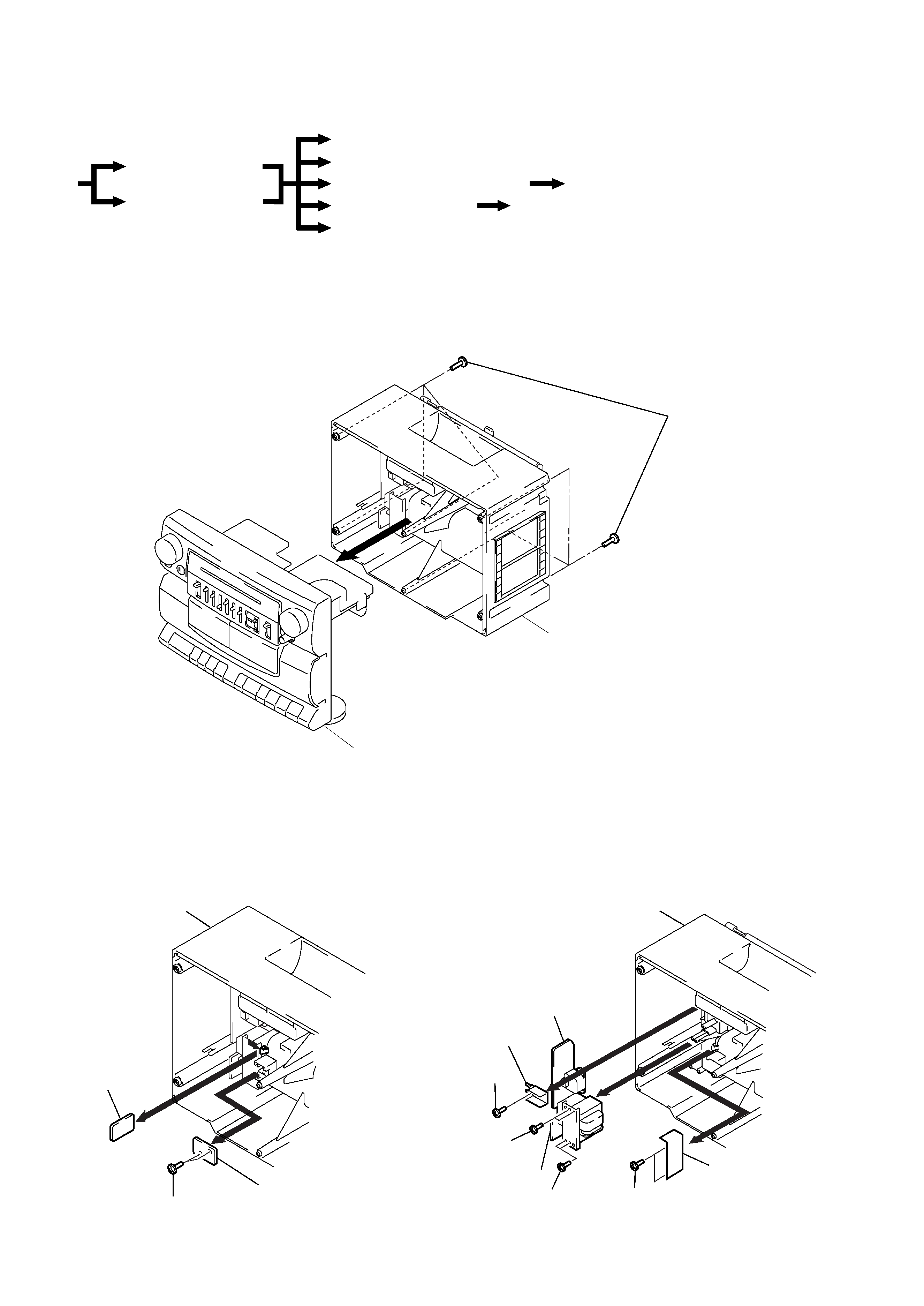
2-1. CABINET (FRONT) SECTION, CABINET (REAR) SECTION
2-2. BATT () BOARD, BATT (+) BOARD
r
The equipment can be removed using the following procedure.
Cabinet (Front) section
BATT () board, BATT (+) board
Cabinet (Rear) section
Set
Power (AC) board, Power (DC) board
Mechanism deck, REC SW board
Chassis sub assy, Belt
VOL board, Main board
ECM board
Tuner board
2-3. POWER (AC) BOARD, POWER (DC) BOARD
Cabinet (Rear) section
Bracket (AC)
5 Screws (+BTP 3x10)
3 Screws
(+BTP 3x10)
1 Screw
(+BTP 3x10)
2
4
6
Power (AC) board
Shield plate (T)
Power (DC) board
3 Screws
(+BTP 3x10)
Cabinet (Rear) section
1 Screws (+BTP 3x10)
3
4
2
BATT (+) board
BATT () board
Cabinet (Rear) section
1 Screws
(+BTP 3x14)
2
Cabinet (Front) section
5
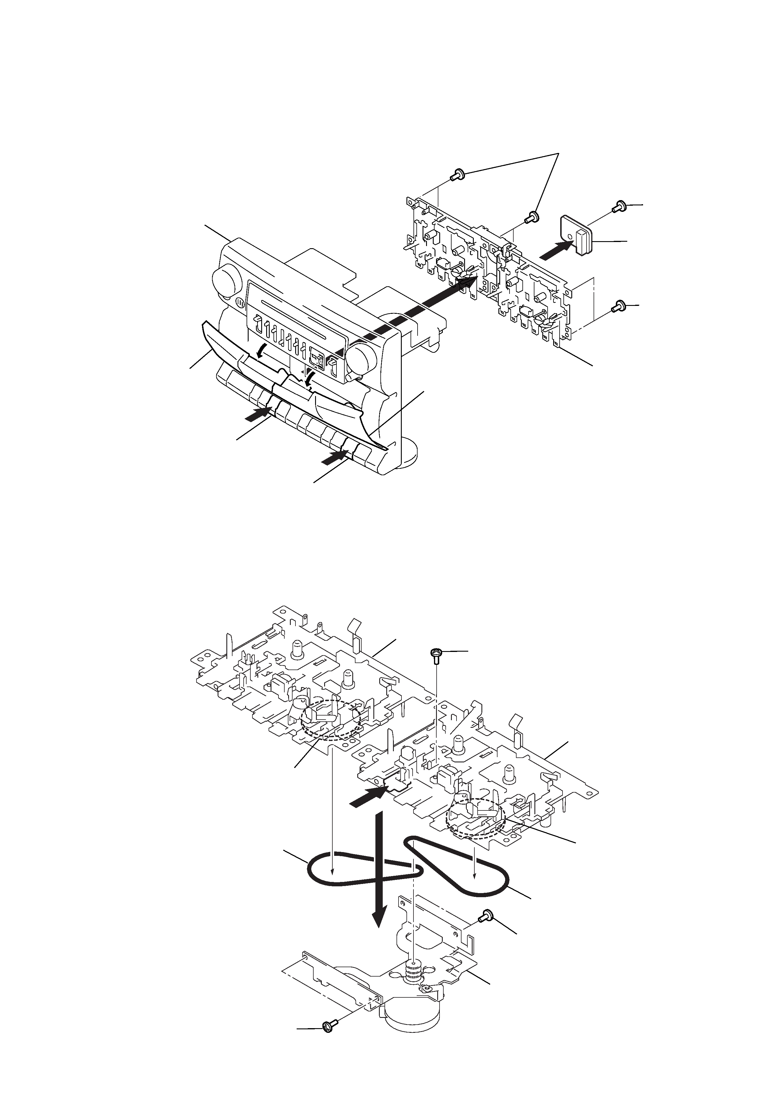
2-4. MECHANISM DECK, REC SW BOARD
2-5. CHASSIS SUB ASSY, BELT
2 Screw (+PTT 2x5)
1
3
Deck B
2 Screws (+PTT 2x5)
4 Belt
4 Belt
2 Screws (+PTT 2x5)
Deck A
Flywheel assy
Chassis sub assy
Flywheel assy
3 Screws
(+BTP 3x10)
3 Screws
(+BTP 3x10)
5 Screw
(+PTT 2x6)
6
4
1
2
1
Button (ST/EJ)
Cassette lid (L)
REC SW board
Cassette lid (R)
Mechanism deck section
Button (ST/EJ)
Cabinet (Front) section
2