ORDER NO.
PIONEER CORPORATION 4-1, Meguro 1-chome, Meguro-ku, Tokyo 153-8654, Japan
PIONEER ELECTRONICS (USA) INC. P.O. Box 1760, Long Beach, CA 90801-1760, U.S.A.
PIONEER EUROPE NV Haven 1087, Keetberglaan 1, 9120 Melsele, Belgium
PIONEER ELECTRONICS ASIACENTRE PTE. LTD. 253 Alexandra Road, #04-01, Singapore 159936
PIONEER CORPORATION 2003
RRV2762
T ZZM APR. 2003 Printed in Japan
S-PR7-S-LR
FOR PRECAUTION OF
REASSEMBLY AND DISASSEMBLY
65S
This service manual is intended for qualified service technicians; it is not meant
for the casual do-it-yourselfer. Qualified technicians have the necessary test
equipment and tools, and have been trained to properly and safely repair complex
products such as those covered by this manual.
Improperly performed repairs can adversely affect the safety and reliability
of the product and may void the warranty. If you are not qualified to perform the
repair of this product properly and safely, you should not risk trying to do so and
refer the repair to a qualified service technician.
WARNING
This product contains lead in solder and certain electrical parts contain chemicals
which are known to the state of California to cause cancer, birth defects or other
reproductive harm.
Health & Safety Code Section 25249.6 Proposition 65
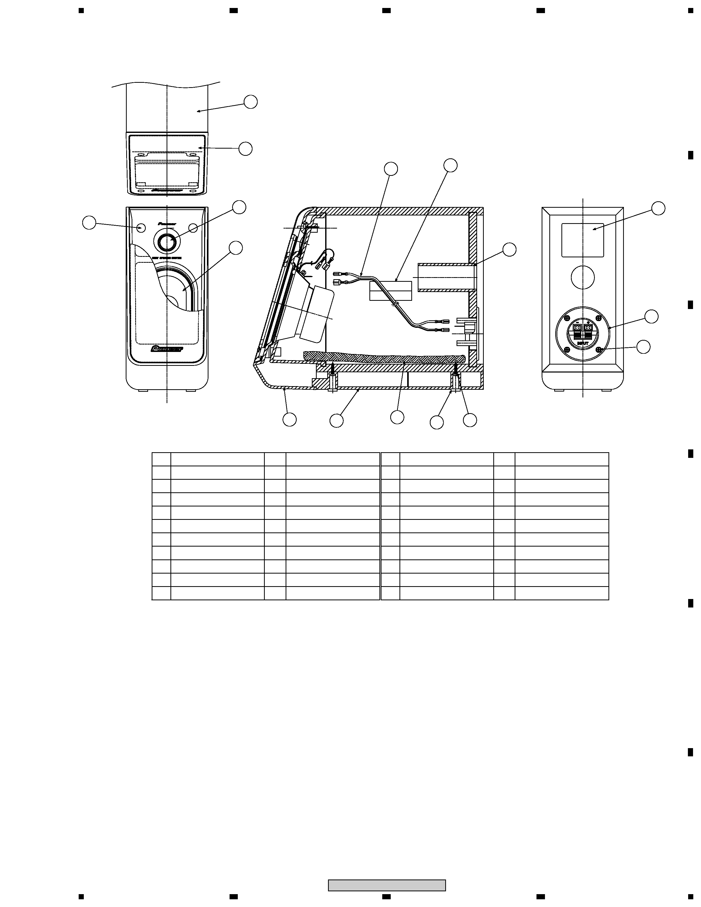
The grille is attached to the cabinet by catches. Detach by pull-
ing it toward you.
The woofer is attached to the inner baffle by 4 external screws.
To detach it, first remove the cosmetic baffle assy. Then unfas-
ten those screws. When attaching it, face its terminal upward.
The tweeter is attached to the inner baffle by external adhesive
double-coated tape. To detach it, first remove the cosmetic
baffle assy and the woofer. Then remove the tweeter together
with adhesive tape. When attaching it, first turn off the back
cover of adhesive double-coated tape and face its cord down-
ward. Next go it through the slit of the inner baffle. Then attach
the adhesive tape there not to project.
S-PR7-S-LR
SPEAKER SYSTEM
XCN/WL
The input terminal is attached to the back board applied with
adhesive by 4 screws. To detach it, unfasten those screws and
pry it open by inserting a flat blade screwdriver between the
back board and the input terminal. Then detach the connection
cord. To attach it, apply adhesive to the back board and face its
red terminal rightward. Then attach it by 4 screws.
2
1
23
4
12
3
4
C
D
F
A
B
E
S-PR7-S-LR
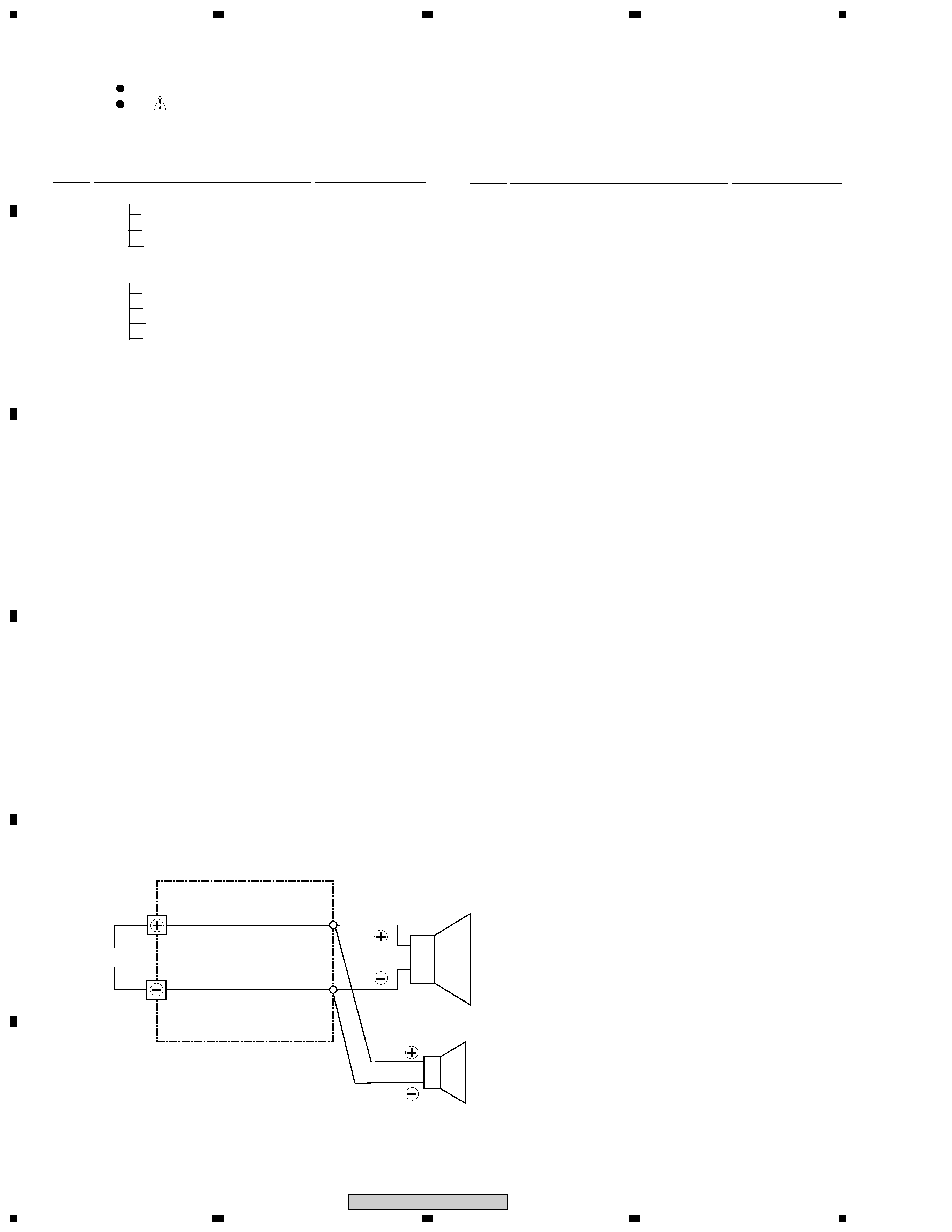
Connection Cord (SDD1315)
SCHEMATIC DIAGRAM
For Packing
Parts marked by "NSP" are generally unavailable because they are not in our Master Spare Parts List.
The
mark found on some component parts indicates the importance of the safety factor of the part.
Therefore, when replacing, be sure to use parts of identical designation.
NOTES:
PARTS LIST
Mark No.
Description
Part No.
Mark No.
Description
Part No.
NSP
Cabinet
SMM1985
Connection Cord
SDD1315
NSP
Paper Tube
SMR1364
NSP
Inner Baffle
SNK2650
Grille Ass'y
SMG1784
NSP
Badge 36
SAM1493
NSP
Grille Cloth
SAS1548
NSP
Grille Frame
SMH1068
Catch
SNK2601
NSP
Model Label
SAN3205
Speaker Wire
SDS1138
Packing (for Woofer)
SEC1681
Packing (for Cos. Baffle)
SEC1702
Non Skid Pad
SEC1682
Input Terminal
SKX1082
NSP
Acoustic Absorbent
SMV2165
Cosmetic Baffle
SNK2651
Base
SNK2652
Speaker (Woofer)
029-09704-844-001
Speaker (Tweeter)
029-03000-000
Screw (for Woofer)
BPZ40P080FZB
Screw (for Base)
BPZ30P140FMC
Screw (for Input Terminal)
CNC30P140FZK
Boss Head Screw (for Cos. Baffle) SBA1223
NSP
Color Label(Grey)
SAX1402
Protector (TOP)
SHA2375
Protector (BOTTOM)
SHA2376
Protection Sheet S3
SHC1794
Separator
SHD1053
Poly Bag S5
SHL1357
I N
Woofer
Blue
White
Tweeter
Transparency
Transparency
with blue line
Black
Red
3
1
23
4
1
2
3
4
C
D
F
A
B
E
S-PR7-S-LR
PRODUCT APPEARANCE
Speaker
9
8
7
1
Connection Cord
Woofer
Acoustic Absorbent
Cabinet
1
1
4
4
1
1
1
1
6
5
4
3
2
1
Remarks
Remarks
Part Name
Part Name
Num.
Num.
No.
No.
Tweeter
Cosmetic Baffle
Speaker
1
Grille
Paper Tube
Model Label
1
Screw
1
2
1
4
Input Terminal
Screw
Boss Head Screw
1
CNC30P140FZK
BPZ30P140FMC
Base
Corner Block
1
2
3
4
8
5
6
7
9
10
85 x 190
11
12
13
14
15
16
17
18
19
20
ø11
11
12
14
13
15
16
10
Non Skid Pad