ORDER NO.
PIONEER ELECTRONIC CORPORATION 4-1, Meguro 1-Chome, Meguro-ku, Tokyo 153-8654, Japan
PIONEER ELECTRONICS SERVICE, INC. P.O. Box 1760, Long Beach, CA 90801-1760, U.S.A.
PIONEER ELECTRONIC (EUROPE) N.V. Haven 1087, Keetberglaan 1, 9120 Melsele, Belgium
PIONEER ELECTRONICS ASIACENTRE PTE. LTD. 253 Alexandra Road, #04-01, Singapore 159936
PIONEER ELECTRONIC CORPORATION 1999
NYXCN
AC230V
NVXCN
AC230V
CD RECEIVER SYSTEM
RRV2136
TZZR MAY 1999 Printed in Japan
X-HX700
CONTENTS
1. SAFETY INFORMATION .................................... 2
2. EXPLODED VIEWS AND PARTS LIST ............. 3
3. BLOCK DIAGRAM AND SCHEMATIC DIAGRAM 8
4. PCB CONNECTION DIAGRAM ....................... 22
5. PCB PARTS LIST ............................................. 30
6. ADJUSTMENT .................................................. 33
7. GENERAL INFORMATION .............................. 35
7.1 DIAGNOSIS ............................................... 35
7.2 PARTS ....................................................... 37
8. PANEL FACILITIES AND SPECIFICATIONS
................................................................... 49
THIS MANUAL IS APPLICABLE TO THE FOLLOWING MODEL(S) AND TYPE(S).
System Component Table
Remarks
Type
Model
X-HX700
Power Requirement
CD RECEIVER AMPLIFIER
XC-HX700
RRV2136
This service manual
SPEAKER SYSTEM
S-HX700-LR
RRV2136
This service manual
MD RECORDER
MJ-HX700
RRV 2134
Remarks
Component
System
X-HX700
Service Manual
X-HX700
2
This service manual is intended for qualified service technicians; it is not meant for the casual
do-it-yourselfer. Qualified technicians have the necessary test equipment and tools, and have been
trained to properly and safely repair complex products such as those covered by this manual.
Improperly performed repairs can adversely affect the safety and reliability of the product and may
void the warranty. If you are not qualified to perform the repair of this product properly and safely, you
should not risk trying to do so and refer the repair to a qualified service technician.
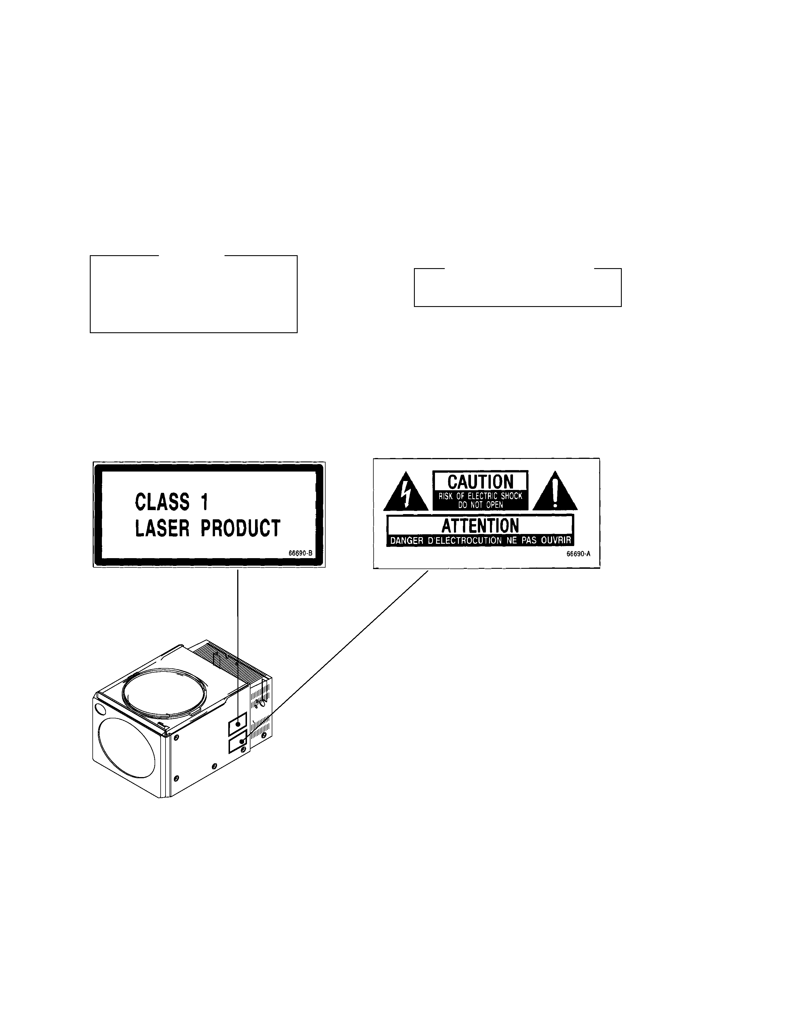
1. SAFETY INFORMATION
LASER DIODE CHARACTERISTICS
MAXIMUM OUTPUT POWER: 5 mw
WAVELENGTH: 780 785 nm
IMPORTANT
THIS PIONEER APPARATUS CONTAINS
LASER OF CLASS 1.
SERVICING OPERATION OF THE APPARATUS
SHOULD BE DONE BY A SPECIALLY
INSTRUCTED PERSON.
REAR
FRONT
LABEL CHECK
X-HX700
3
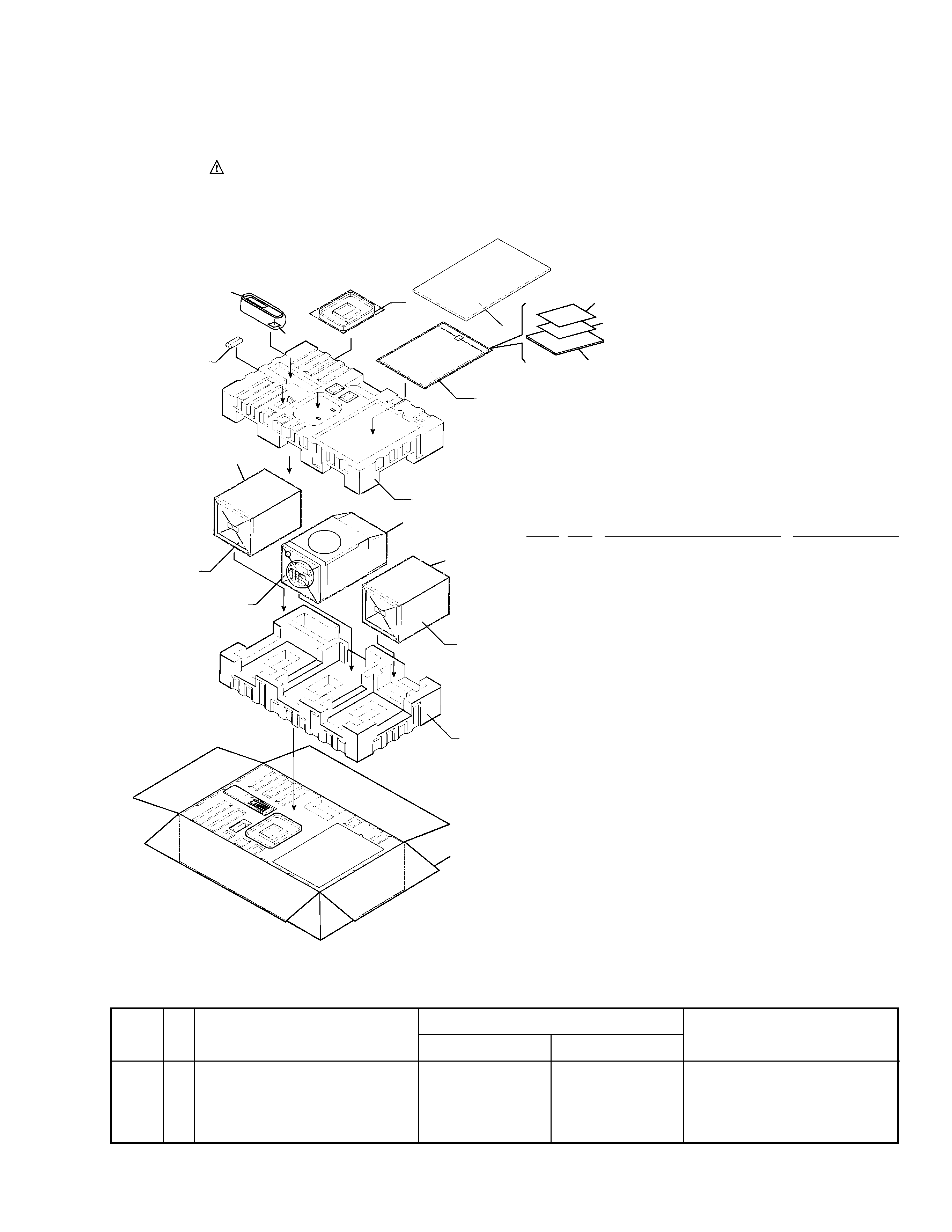
2. EXPLODED VIEWS AND PARTS LIST
2.1 PACKING
(1)PACKING PARTS LIST
NSP
1
CD RECEIVER
See Contrast table (2)
NSP
2
SPEAKER SYSTEM
See Contrast table (2)
3
Display Carton
See Contrast table (2)
4
Mirrormat Bag (400
× 300× 0.5)
66794
5
Remote Control Unit (REA-22C) 60231A
6
Battery Cover
60231-01
7
Operating Instruction (English)
66780-CDU
7
Operating Instruction (French)
66780-CDF
7
Operating Instruction (German)
66780-CDG
NSP
8
Dry Cell Battery (R6P, AA)
60235
9
Mirrormat Bag (360
× 300× 0.5)
66692
(SPEAKER BOX)
10
AM Loop Ant . Assy
60232
11
Poly Foam B (TOP)
66682
12
Poly Foam B (BOTTOM)
66683
13
Carton Sheet B
66678
14
SAFETY DIRECTION
See Contrast table (2)
15
GUARANTEE CARD
66689-Y/V
16
Poly Bag
53117
Mark No.
Description
Parts No.
(2) CONTRAST TABLE
X-HX700/NYXCN and X-HX700/NVXCN are constructed the same except for the following:
NOTES :
÷ Parts marked by " NSP " are generally unavailable because they are not in our Master Spare Parts List.
÷ The
mark found on some component parts indicates the importance of the safety factor of the part.
Therefore, when replacing, be sure to use parts of identical designation.
÷ Screw adjacent to
mark on the product are used for disassembly.
14
16
15
7
11
13
8
9
10
9
2
2
1
4
12
3
5
6
Mark
X-HX700/NYXCN
X-HX700/NVXCN
NSP
1
CD RECEIVER
XC-HX700/NYXCN
XC-HX700/NVXCN
NSP
2
SPEAKER SYSTEM
S-HX700-LR
S-HX700-LR
3
Display Carton
66677-70Y
66677-70V
14
SAFETY DIRECTION
66784-70Y
66784-70V
Part No.
Remarks
Symbol and Description
No.
X-HX700
4
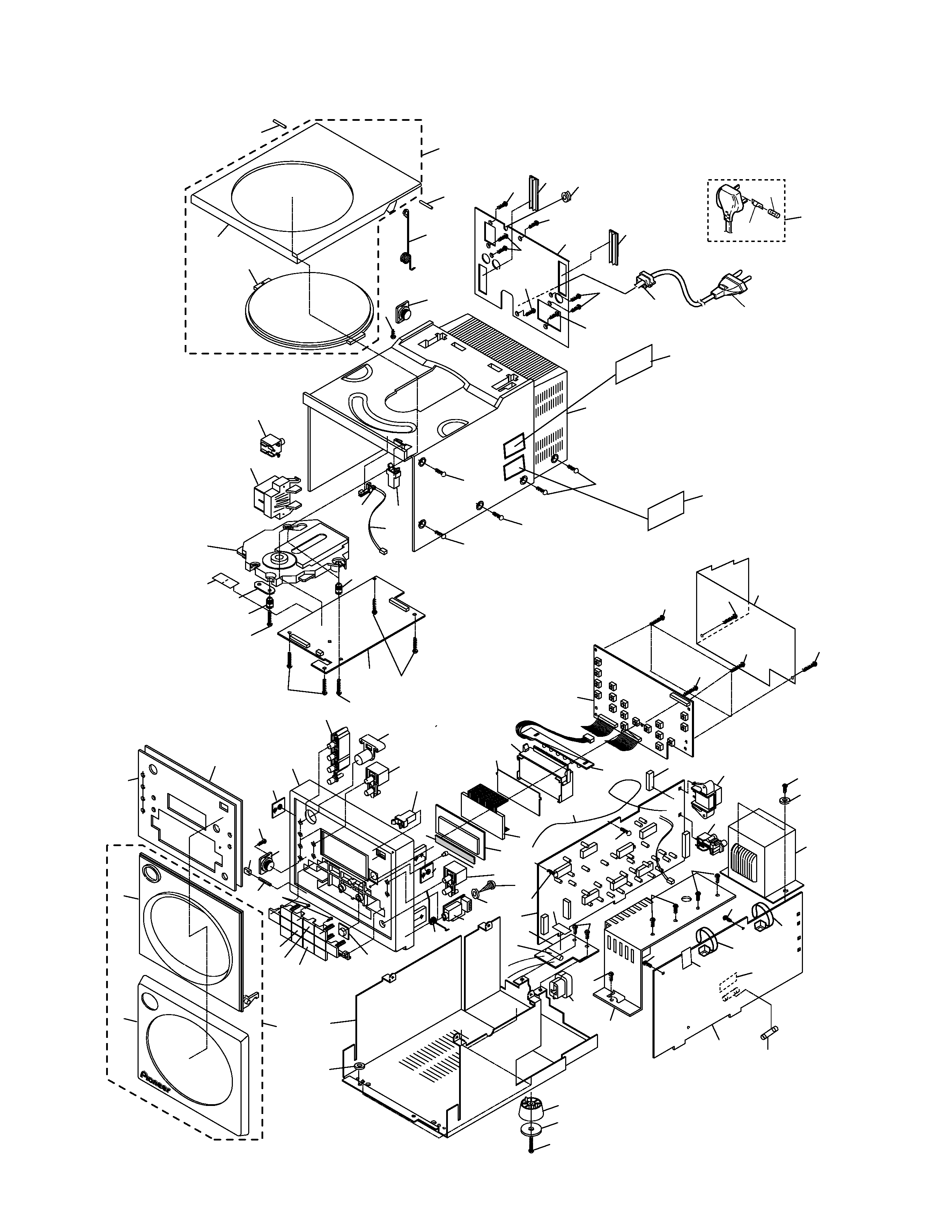
2.2 EXTERIOR
Fuse Holder
NVXCN type Only
57
57
61
55
3
3
3
3
3
71
59
42
43
72
73
82
58
24
56
55
55
54
74
33
55
62
62
50
52
8
3
3
13
12
11
3
55
53
67
51
39
41
40
78
78
69
3
3
3
3
3
80
3
3
10
9
4
4
25
65
63
31
30
32
32
8
28
38
33
34
24
24
24
24
68
24
70
45
24
29
26
76
79
7
6
1
5
22
16
66
15
14
18
17
21
60
23
19
64
20
37
3
2
83
36
35
44
47
49
48
46
75
81
77
84
77
CD Mechanism assembly
has no service part.
X-HX700
5
(1) EXTERIOR PARTS LIST
Mark No.
Description
Parts No.
(2) CONTRAST TABLE
XC-HX700/NYXCN and XC-HX700/NVXCN are constructed the same except for the following:
Mark No.
Description
Parts No.
1
Inner Panel (CD)
66710-K7C
2
Dumper Gear
60108
3
Screw PAN TAPP. T3X10
PBZ30P100FZK
4
Plate Nut
66741
5
Button C (SET)
66718-K7S
6
Power Button
66720-K7
7
Button D (TIMER)
66719
8
Push Door Lock
60226
9
LCD Assy
52716
10
LCD Sheet
66756
11
LCD Holder
66727
NSP
12
LED PCB Assy
66788B
13
FRONT CD PCB Assy
66788A
14
Door Shaft A
66746
15
Screw PAN TAPP. T2X8
PBZ20P080FMC
16
Cushion A
66795
NSP
17
Front Door A (CD)
66706-K7C
18
Button B (CD-2)
66717-K7C2
19
Button A (CD-1)
66716-K7C1
20
Lens
66734-CD
NSP
21
Front Cover A (CD)
66712-K7C
22
CD Front Case
66701-K7
NSP
23
CD Rear Chassis
66737
24
Screw BIND M3X6
BMZ30P060FZK
25
LCD Window
66735
26
Lens (STANDBY)
66736
27
Screw BIND TAPP. T3X8
BBZ30P080FZK
28
AMP COMBI PCB Assy
66789C
(HEADPHONE PCB)
29
Front Door Spring
66748
30
TUNER PCB Assy
66675
31
AMP COMBI PCB Assy
66789B
(FUSE PCB)
32
Screw BTT-S T3X8
BSZ30P080FMC
33
AC Cord Bushing
60228
34
Heat Sink
66743
35
Screw PAN M3X8
PMZ30P080FZK
36
Leg Rubber A
66758-01
37
Foot A
66722-01
38
AMP COMBI PCB Assy
66789A
(POWER PCB)
39
CD PCB Assy
66786
40
Cushion Rubber
60230
41
Holder Plate
66742
NSP
42
CD Door
67705-K7
NSP
43
CD Door Window
66733-OV
NSP
44
Anntena Wire
66779
45
AM Anntena Jack
60243
46
Pin JAck
52526
47
Power Transformer
54516
48
Screw BIND M4X6
BMZ40P060FMC
49
Washer
WS40FMC
50
1P pin Jack
52525
51
Speaker Terminal
60246
52
CD Mechanism Assy
61417
53
Leaf Switch
52802
54
LABEL PLATE (CLASS1)
66690E
55
Screw FLAT M3X6
CMZ30P060FNI
56
CD Rear Case
66703-K7
57
Door Shaft B
66747
58
Rear Panel
See Contrast table (2)
59
CD Door Spring
66749
60
Front Door A Assy (CD)
10200-K7C
61
CD Door Assy
10400-K7
62
AC Power Cord
See Contrast table (2)
63
Fuse (F301 : T4A/250V)
51609
64
Button A (CD-3)
66716-K7C3
65
Button D (DISPLAY)
66719-K7D
66
Panel Tape A
66760
67
Connector Assy (2P)
66772
68
Fuse Label (T4A/250V)
60270
69
Cushion Rubber
60229
70
Cushion B
66796
71
Dumper Gear
60227
72
10P Connector Cover
66685
73
12p Connector Cover
66684
74
LABEL PLATE (CAUTION)
66690I
75
Fuse (F302 : T315mA/250V)
51608
76
Washer
55003
77
Cable Tie
60208
78
Hymeron
51907
79
Barrier Plate
66693
80
Shield Plate
66797
81
Fuse
See Contrast table (2)
82
Motor Cushion
60143
83
Cushion Washer
66699
84
Fuse Label (T315mA/250V)
60269
Mark
X-HX700/NYXCN
X-HX700/NVXCN
58
Rear Panel
66740-70Y
66740-70V
62
AC Power Cord
50322
50321
81
Fuse (T5A : For AC Power Cord)
Not used
PEK1003
Part No.
Remarks
Symbol and Description
No.