ORDER NO.
PIONEER ELECTRONIC CORPORATION 4-1, Meguro 1-Chome, Meguro-ku, Tokyo 153-8654, Japan
PIONEER ELECTRONICS SERVICE, INC. P.O. Box 1760, Long Beach, CA 90801-1760, U.S.A.
PIONEER ELECTRONIC (EUROPE) N.V. Haven 1087, Keetberglaan 1, 9120 Melsele, Belgium
PIONEER ELECTRONICS ASIACENTRE PTE. LTD. 253 Alexandra Road, #04-01, Singapore 159936
PIONEER ELECTRONIC CORPORATION 1999
c
VSX-29TX
RRV2133
1. SAFETY INFORMATION ...................................... 2
2. EXPLODED VIEWS AND PARTS LIST ............... 3
3. BLOCK DIAGRAM AND SCHEMATIC DIAGRAM ... 10
4. PCB CONNECTION DIAGRAM ......................... 48
5. PCB PARTS LIST ............................................... 71
6. ADJUSTMENT .................................................... 83
CONTENTS
7. GENERAL INFORMATION ................................ 84
7.1 DISASSEMBLY ............................................ 84
7.2 PARTS .......................................................... 86
7.2.1 IC ............................................................ 86
7.2.2 DISPLAY ................................................. 90
7.3 REMOTE CONTROL UNIT .......................... 92
8. PANEL FACILITIES AND SPECIFICATIONS ..... 103
T IZK MAY 1999 Printed in Japan
VSX-27TX
AUDIO/VIDEO MULTI-CHANNEL RECEIVER
VSX-26TX
VSX-24TX
VSX-D908S
Type
Model
Power Requirement
Remarks
VSX-29TX
VSX-27TX
VSX-26TX
VSX-24TX
VSX-D908S
KU/CA
AC120V
THIS MANUAL IS APPLICABLE TO THE FOLLOWING MODEL(S) AND TYPE(S).
STANDBY/ON
DSP
MODE
MULTI-ROOM
& SOURCE
INPUT
SELECTOR
MASTER
VOLUME
MIN
MAX
THX CINEMA
ADVANCED
STANDARD
CONTROL
VIDEO
VCR 1
VCR 2
DVD/LD
TV/SAT
CD
MD/TAPE1
TUNER
PHONO
STANDBY
AUDIO/VIDEO MULTI-CHANNEL RECEIVER
STEREO
/DTS
Nm¿</im
REFERENCE AUDIO/VIDEO MULTICHANNEL RECEIVER
2
VSX-29TX, VSX-27TX, VSX-26TX,
VSX-24TX, VSX-D908S
1. SAFETY INFORMATION
This service manual is intended for qualified service technicians ; it is not meant for the casual do-it-
yourselfer. Qualified technicians have the necessary test equipment and tools, and have been trained
to properly and safely repair complex products such as those covered by this manual.
Improperly performed repairs can adversely affect the safety and reliability of the product and may
void the warranty. If you are not qualified to perform the repair of this product properly and safely, you
should not risk trying to do so and refer the repair to a qualified service technician.
WARNING
This product contains lead in solder and certain electrical parts contain chemicals which are known to the state of California to cause
cancer, birth defects or other reproductive harm.
Health & Safety Code Section 25249.6 Proposition 65
NOTICE
(FOR CANADIAN MODEL ONLY)
Fuse symbols
(fast operating fuse) and/or
(slow operating fuse) on PCB indicate that replacement parts must
be of identical designation.
REMARQUE
(POUR MODÈLE CANADIEN SEULEMENT)
Les symboles de fusible
(fusible de type rapide) et/ou
(fusible de type lent) sur CCI indiquent que les pièces
de remplacement doivent avoir la même désignation.
ANY MEASUREMENTS NOT WITHIN THE LIMITS
OUTLINED ABOVE ARE INDICATIVE OF A POTENTIAL
SHOCK HAZARD AND MUST BE CORRECTED BEFORE
RETURNING THE APPLIANCE TO THE CUSTOMER.
2. PRODUCT SAFETY NOTICE
Many electrical and mechanical parts in the appliance
have special safety related characteristics. These are
often not evident from visual inspection nor the protection
afforded by them necessarily can be obtained by using
replacement components rated for voltage, wattage, etc.
Replacement parts which have these special safety
characteristics are identified in this Service Manual.
Electrical components having such features are identified
by marking with a
on the schematics and on the parts list
in this Service Manual.
The use of a substitute replacement component which does
not have the same safety characteristics as the PIONEER
recommended replacement one, shown in the parts list in
this Service Manual, may create shock, fire, or other hazards.
Product Safety is continuously under review and new
instructions are issued from time to time. For the latest
information, always consult the current PIONEER Service
Manual. A subscription to, or additional copies of, PIONEER
Service Manual may be obtained at a nominal charge from
PIONEER.
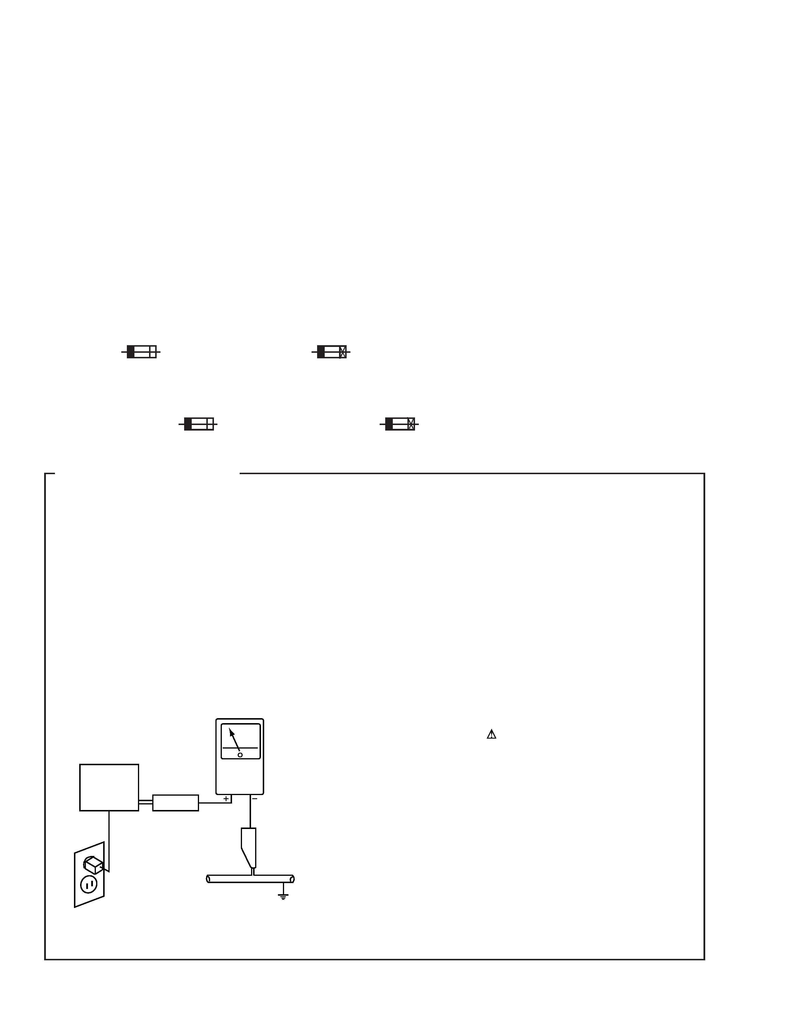
1. SAFETY PRECAUTIONS
The following check should be performed for the
continued protection of the customer and service
technician.
LEAKAGE CURRENT CHECK
Measure leakage current to a known earth ground (water
pipe, conduit, etc.) by connecting a leakage current tester
such as Simpson Model 229-2 or equivalent between the
earth ground and all exposed metal parts of the appliance
(input/output terminals, screwheads, metal overlays, control
shaft, etc.). Plug the AC line cord of the appliance directly
into a 120V AC 60Hz outlet and turn the AC power switch
on. Any current measured must not exceed 0.5mA.
(FOR USA MODEL ONLY)
Leakage
current
tester
Reading should
not be above
0.5mA
Device
under
test
Test all
exposed metal
surfaces
Also test with
plug reversed
(Using AC adapter
plug as required)
Earth
ground
AC Leakage Test
3
VSX-29TX, VSX-27TX, VSX-26TX,
VSX-24TX, VSX-D908S
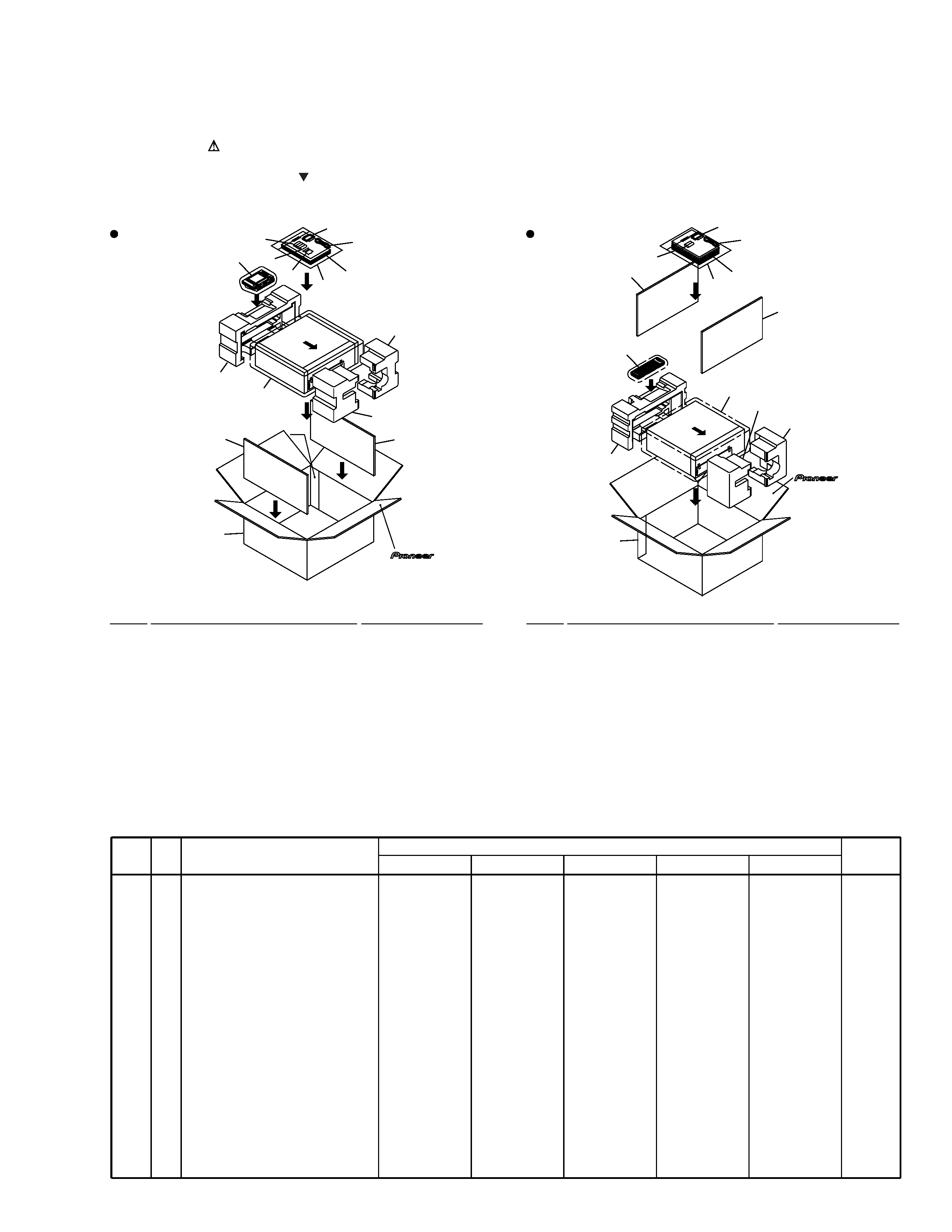
2.1 PACKING
2. EXPLODED VIEWS AND PARTS LIST
NOTES:
· Parts marked by "NSP" are generally unavailable because they are not in our Master Spare Parts List.
· The mark found on some component parts indicates the importance of the safety factor of the part.
Therefore, when replacing, be sure to use parts of identical designation.
· Screws adjacent to mark on the product are used for disassembly.
VSX-29TX
Other Models
1
2
3, 12
Refer to
"7.3 REMOTE
CONTROL UNIT".
Refer to
"7.3 REMOTE
CONTROL UNIT".
11
6
5
4
8
5
1
2
13
13
3, 12
11
10
5
4
10
13
13
9
7 (1/2)
7 (2/2)
7 (1/2)
7 (2/2)
8
9
(1) PACKING PARTS LIST
Mark No.
Description
Part No.
1
AM Loop Antenna
ATB7009
2
FM Wire Antenna
ADH1015
3
Operating Instructions
See Contrast table (2)
(English)
4
Remote Control Unit
See Contrast table (2)
NSP
5
Alkaline Dry Cell Battery
VEM1012
(LR6, AA)
6
Cushion for Remote
See Contrast table (2)
(for Remote Control Unit)
7
Front Pad
See Contrast table (2)
Mark No.
Description
Part No.
8
Rear Pad
See Contrast table (2)
9
Packing Case
See Contrast table (2)
10
Packing Sheet
RHC1023
11
Polyethylene Bag
Z21-038
(0.03
×230×340)
NSP
12
Warranty Card
See Contrast table (2)
13
Spacer
See Contrast table (2)
Mark No.
Symbol and Description
Part No.
Remaks
VSX-29TX
VSX-27TX
VSX-26TX
VSX-24TX
VSX-D908S
NSP
3
4
4
4
6
7
7
8
8
9
9
9
9
9
12
12
13
13
Operating Instructions (English)
Remote Control Unit (CU-VSX158)
Remote Control Unit (CU-VSX159)
Remote Control Unit (CU-VSX161)
Cushion for Remote
Front Pad 29
Front Pad 26
Rear Pad 29
Rear Pad 26
Packing Case 29TX
Packing Case 27TX
Packing Case 26TX
Packing Case 24TX
Packing Case 908S
Warranty Card EL
Warranty Card PA
Spacer 29
Spacer 26
ARB7188
AXD7216
Not used
Not used
AXG7080
AHA7255
Not used
AHA7256
Not used
AHD7810
Not used
Not used
Not used
Not used
ARY1026
Not used
AHB7033
Not used
ARB7186
Not used
AXD7212
Not used
Not used
Not used
AHA7253
Not used
AHA7254
Not used
AHD7783
Not used
Not used
Not used
ARY1026
Not used
Not used
AHB7032
ARB7186
Not used
AXD7212
Not used
Not used
Not used
AHA7253
Not used
AHA7254
Not used
Not used
AHD7811
Not used
Not used
ARY1026
Not used
Not used
AHB7032
ARB7186
Not used
AXD7212
Not used
Not used
Not used
AHA7253
Not used
AHA7254
Not used
Not used
Not used
AHD7784
Not used
ARY1026
Not used
Not used
AHB7032
ARB7193
Not used
Not used
AXD7213
Not used
Not used
AHA7253
Not used
AHA7254
Not used
Not used
Not used
Not used
AHD7785
Not used
ARY7023
Not used
AHB7032
(2) CONTRAST TABLE
VSX-29TX, VSX-27TX, VSX-26TX, VSX-24TX and VSX-D908S are constructed the same except for the following :
4
VSX-29TX, VSX-27TX, VSX-26TX,
VSX-24TX, VSX-D908S
C
A
B
G
F
F
E
E
N
L
I
K
H
H
J
G
I
J
O
O
M
M
N
L
K
P
P
56
57
68
20
74
75
27
67
VSX-29TX Only
VSX-29TX Only
VSX-29TX, VSX-27TX Only
(Except
VSX-29TX)
74
75
73
73
10
11
71
71
43
24
25
21
6
(Except
VSX-29TX)
73
67
67
26
43
67
70
67
69
53
69
32
8
67
62
52
52
52
7
67
67
36
48
49
40
49
49
60
61
34
45
50
51
39
29
5
9
18
67
51
67
67
38
35
1 or 2
3
4
55
70
70
70
70
44
44
42
42
67
19
72
14
72
66 (VSX-29TX)
VSX-29TX
Only
VSX-29TX
Only
VSX-29TX,
VSX-27TX
Only
67 (OTHERS)
66 (VSX-29TX)
67 (OTHERS)
66 (VSX-29TX)
67 (OTHERS)
66 (VSX-29TX)
67 (OTHERS)
66 (VSX-29TX)
67 (OTHERS)
66 (VSX-29TX)
67 (OTHERS)
66 (VSX-29TX)
67 (OTHERS)
66
(VSX-29TX)
67
(OTHERS)
66 (VSX-29TX)
67 (OTHERS)
66 (VSX-29TX)
67 (VSX-27TX)
66 (VSX-29TX)
26
(VSX-26TX,
VSX-24TX,
VSX-D908S Only)
VSX-29TX,
VSX-27TX
Only)
67 (OTHERS)
66
(VSX-29TX)
67
(VSX-27TX)
59
50
58
Refer to
"2.4 FRONT PANEL SECTION".
Refer to
"2.3 HEAT SINK SECTION".
66 (VSX-29TX)
67 (OTHERS)
64
37 15
23
33
13
54
12
16
30
17
63
28
31
65
22
51
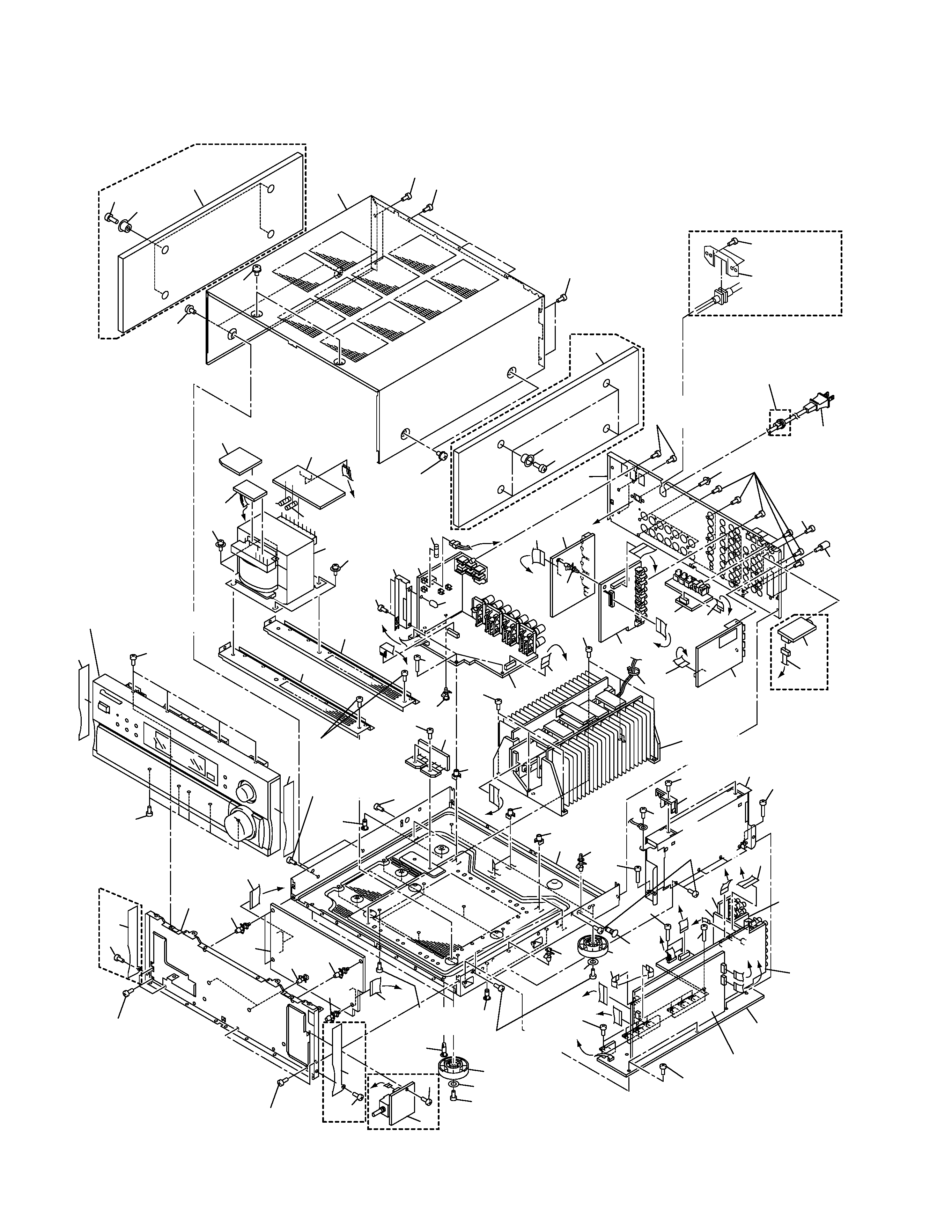
2.2 EXTERIOR

5
VSX-29TX, VSX-27TX, VSX-26TX,
VSX-24TX, VSX-D908S
NSP
1
EXTRA-5.1 Assy
See Contrast table (2)
NSP
2
EXTERNAL IN Assy
See Contrast table (2)
NSP
3
A-PINJACK Assy
See Contrast table (2)
4
CONNECTION Assy
AWX7313
5
MAIN CONTROL Assy
See Contrast table (2)
6
TRANS 2-1 ASSY
AWX7326
7
DIODE Assy
AWX7343
8
SP/PS Assy
See Contrast table (2)
9
REGULATOR Assy
AWX7310
10
TRANS 1 Assy
AWX7316
11
TRANS 2-2 Assy
AWX7366
12
VIDEO Assy
See Contrast table (2)
13
S-VIDEO Assy
See Contrast table (2)
14
VOLUME Assy
See Contrast table (2)
15
PRIMARY Assy
AWX7311
16
DIGITAL-I/O Assy
See Contrast table (2)
NSP
17
RF TERMINAL Assy
See Contrast table (2)
NSP
18
DSP Assy
See Contrast table (2)
19
V-AMP Assy
See Contrast table (2)
20
AC Power Cord
See Contrast table (2)
21
Power Transformer (T1)
ATS7252
22
FM/AM TUNER Unit
AXX7046
23
Fuse (FU1 : 10A)
VEK1029
24
Fuse (FU4 : 2.5A)
REK1079
25
Fuse (FU5 : 2.5A)
REK1079
26
AC Cord Spacer
See Contrast table (2)
27
Bonnet Case
See Contrast table (2)
28
2P Shield with Housing (J24)
See Contrast table (2)
29
Lead Card 07P (J13)
ADD7161
30
Lead Card 11P AD (J22)
ADD7170
31
Lead Card 13P AD (J16)
ADD7169
32
Lead Card 14P (J17)
ADD7165
33
Lead Card 21P (J18)
ADD7164
34
Lead Card 23P BD SLD (J12)
ADD7160
35
Lead Card 26P (J15)
ADD7163
36
Lead Card 28P (J23)
ADD7171
37
Assy Holder
See Contrast table (2)
38
Assy Holder B
AMR7267
39
Card Spacer
AEC7133
40
Card Spacer
DEC1772
41
· · · · ·
42
Cushion 55
PNM1316
NSP
43
Frame
See Contrast table (2)
44
Insulator
PNW2766
45
Locking Card Spacer
DEC1908
46
· · · · ·
47
· · · · ·
NSP
48
Panel Stay
See Contrast table (2)
49
PC Support
VEC1549
NSP
50
PCB Holder
AEC7057
NSP
51
PCB Holder
PNW2100
NSP
52
PCB Mould
AMR1525
53
PCB Spacer
AEC1372
54
Rear Panel
See Contrast table (2)
55
Shield Case
See Contrast table (2)
56
Side Board 29 L
See Contrast table (2)
57
Side Board 29 R
See Contrast table (2)
58
Side Escutheon L
See Contrast table (2)
59
Side Escutheon R
See Contrast table (2)
60
Side Sash L 29
See Contrast table (2)
61
Side Sash R 29
See Contrast table (2)
62
Stud Cover
AEC7105
63
Terminal Screw
AKE-031
NSP
64
Under Base 29
See Contrast table (2)
NSP
65
Binder (BK-1)
ZCA-BK1
66
Screw
BBT30P080FCC
67
Screw
BBZ30P080FZK
68
Screw
ABA1193
69
Screw
IBZ30P080FCC
70
Screw
BBZ30P180FMC
71
Screw
See Contrast table (2)
72
Screw
BBT30P040FZK
73
Screw
FBT40P080FZK
74
Wood Collar
See Contrast table (2)
75
Screw
See Contrast table (2)
Mark No.
Description
Part No.
Mark No.
Description
Part No.
(1) EXTERIOR PARTS LIST