ORDER NO.
PIONEER ELECTRONIC CORPORATION 4-1, Meguro 1-chome, Meguro-ku, Tokyo 153-8654, Japan
PIONEER ELECTRONICS SERVICE, INC. P.O. Box 1760, Long Beach, CA 90801-1760, U.S.A.
PIONEER EUROPE N V Haven 1087, Keetberglaan 1, 9120 Melsele, Belgium
PIONEER ELECTRONICS ASIACENTRE PTE. LTD. 253 Alexandra Road, #04-01, Singapore 159936
PIONEER ELECTRONIC CORPORATION 2000
c
VSX-35TX
RRV2351
1. SAFETY INFORMATION ...................................... 2
2. EXPLODED VIEWS AND PARTS LIST ............... 3
3. BLOCK DIAGRAM AND SCHEMATIC DIAGRAM ..... 8
4. PCB CONNECTION DIAGRAM ......................... 48
5. PCB PARTS LIST ............................................... 76
6. ADJUSTMENT .................................................... 89
CONTENTS
7. GENERAL INFORMATION ................................ 90
7.1 DISASSEMBLY ............................................ 90
7.2 PARTS .......................................................... 92
7.2.1 IC ............................................................ 92
7.2.2 DISPLAY ................................................. 97
7.3 REMOTE CONTROL UNIT ........................ 100
8. PANEL FACILITIES AND SPECIFICATIONS ..... 105
T ZZR AUG. 2000 Printed in Japan
VSX-33TX
AUDIO/VIDEO MULTI-CHANNEL RECEIVER
Type
Model
Power Requirement
Remarks
VSX-35TX
VSX-33TX
KUXJI/CA
KUXJI/CA
AC120V
AC120V
THIS MANUAL IS APPLICABLE TO THE FOLLOWING MODEL(S) AND TYPE(S).
VSX-35TX
REFERENCE AUDIO/VIDEO MULTICHANNEL RECEIVER
2
VSX-35TX, VSX-33TX
1. SAFETY INFORMATION
This service manual is intended for qualified service technicians ; it is not meant for the casual do-it-
yourselfer. Qualified technicians have the necessary test equipment and tools, and have been trained
to properly and safely repair complex products such as those covered by this manual.
Improperly performed repairs can adversely affect the safety and reliability of the product and may
void the warranty. If you are not qualified to perform the repair of this product properly and safely, you
should not risk trying to do so and refer the repair to a qualified service technician.
WARNING
This product contains lead in solder and certain electrical parts contain chemicals which are known to the state of California to cause
cancer, birth defects or other reproductive harm.
Health & Safety Code Section 25249.6 Proposition 65
NOTICE
(FOR CANADIAN MODEL ONLY)
Fuse symbols
(fast operating fuse) and/or
(slow operating fuse) on PCB indicate that replacement parts must
be of identical designation.
REMARQUE
(POUR MODÈLE CANADIEN SEULEMENT)
Les symboles de fusible
(fusible de type rapide) et/ou
(fusible de type lent) sur CCI indiquent que les pièces
de remplacement doivent avoir la même désignation.
ANY MEASUREMENTS NOT WITHIN THE LIMITS
OUTLINED ABOVE ARE INDICATIVE OF A POTENTIAL
SHOCK HAZARD AND MUST BE CORRECTED BEFORE
RETURNING THE APPLIANCE TO THE CUSTOMER.
2. PRODUCT SAFETY NOTICE
Many electrical and mechanical parts in the appliance
have special safety related characteristics. These are
often not evident from visual inspection nor the protection
afforded by them necessarily can be obtained by using
replacement components rated for voltage, wattage, etc.
Replacement parts which have these special safety
characteristics are identified in this Service Manual.
Electrical components having such features are identified
by marking with a
on the schematics and on the parts list
in this Service Manual.
The use of a substitute replacement component which does
not have the same safety characteristics as the PIONEER
recommended replacement one, shown in the parts list in
this Service Manual, may create shock, fire, or other hazards.
Product Safety is continuously under review and new
instructions are issued from time to time. For the latest
information, always consult the current PIONEER Service
Manual. A subscription to, or additional copies of, PIONEER
Service Manual may be obtained at a nominal charge from
PIONEER.
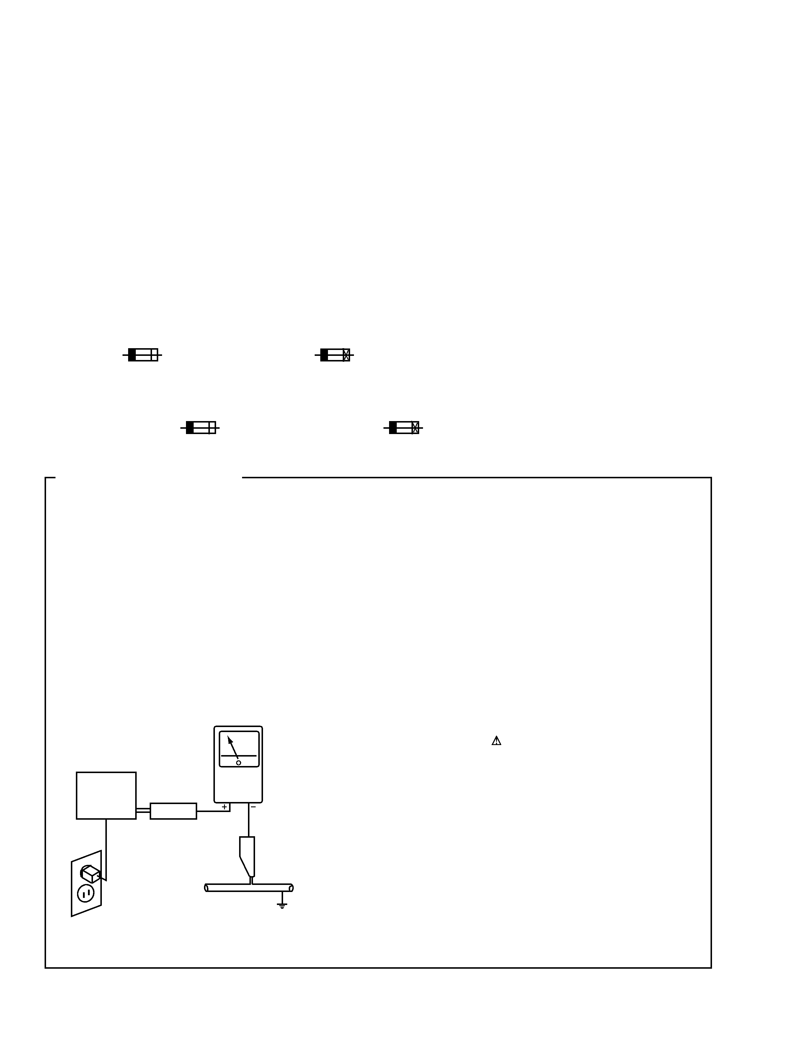
1. SAFETY PRECAUTIONS
The following check should be performed for the
continued protection of the customer and service
technician.
LEAKAGE CURRENT CHECK
Measure leakage current to a known earth ground (water
pipe, conduit, etc.) by connecting a leakage current tester
such as Simpson Model 229-2 or equivalent between the
earth ground and all exposed metal parts of the appliance
(input/output terminals, screwheads, metal overlays, control
shaft, etc.). Plug the AC line cord of the appliance directly
into a 120V AC 60Hz outlet and turn the AC power switch
on. Any current measured must not exceed 0.5mA.
(FOR USA MODEL ONLY)
Leakage
current
tester
Reading should
not be above
0.5mA
Device
under
test
Test all
exposed metal
surfaces
Also test with
plug reversed
(Using AC adapter
plug as required)
Earth
ground
AC Leakage Test
3
VSX-35TX, VSX-33TX
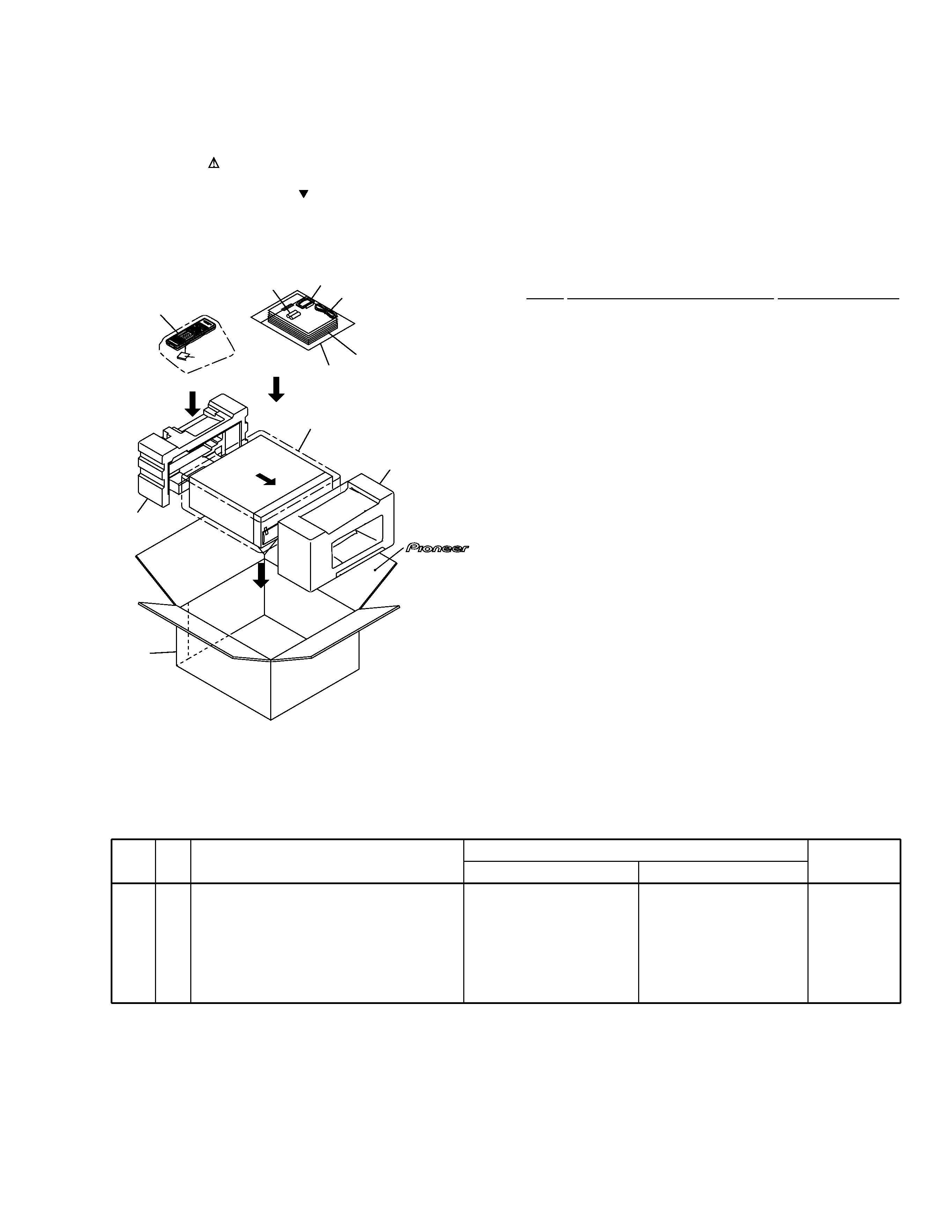
2.1 PACKING
(1) PACKING PARTS LIST
Mark No.
Description
Part No.
2. EXPLODED VIEWS AND PARTS LIST
NOTES:
· Parts marked by "NSP" are generally unavailable because they are not in our Master Spare Parts List.
· The mark found on some component parts indicates the importance of the safety factor of the part.
Therefore, when replacing, be sure to use parts of identical designation.
· Screws adjacent to mark on the product are used for disassembly.
1
AM Loop Antenna
ATB7009
2
FM Wire Antenna
ADH7004
3
Operating Instructions
See Contrast table (2)
(English)
4
Remote Control Unit
See Contrast table (2)
NSP
5
Alkaline Dry Cell Battery
VEM1021
(LR6, AA)
6
Front Pad 35
AHA7287
7
Rear Pad 35
AHA7288
8
Packing Case
See Contrast table (2)
9
Packing Sheet
AHG7010
NSP
10
Polyethylene Bag
Z21-038
(230
× 340 × 0.03)
NSP
11
Warranty Card
ARY7007
12
Battery Cover
See Contrast table (2)
(2) CONTRAST TABLE
VSX-35TX and VSX-33TX are constructed the same except for the following :
Mark No.
Symbol and Description
Part No.
Remarks
VSX-35TX
VSX-33TX
3
4
4
8
8
12
Operating Instructions (English)
Remote Control Unit (35TX)
Remote Control Unit (33TX)
Packing Case 35TX
Packing Case 33TX
Battery Cover
ARB7222
AXD7266
Not used
AHD7860
Not used
AZN7841
ARB7223
Not used
AXD7267
Not used
AHD7861
AZN7826
1
2
3,11
10
12
9
5
4
6
7
8
FRONT
4
VSX-35TX, VSX-33TX
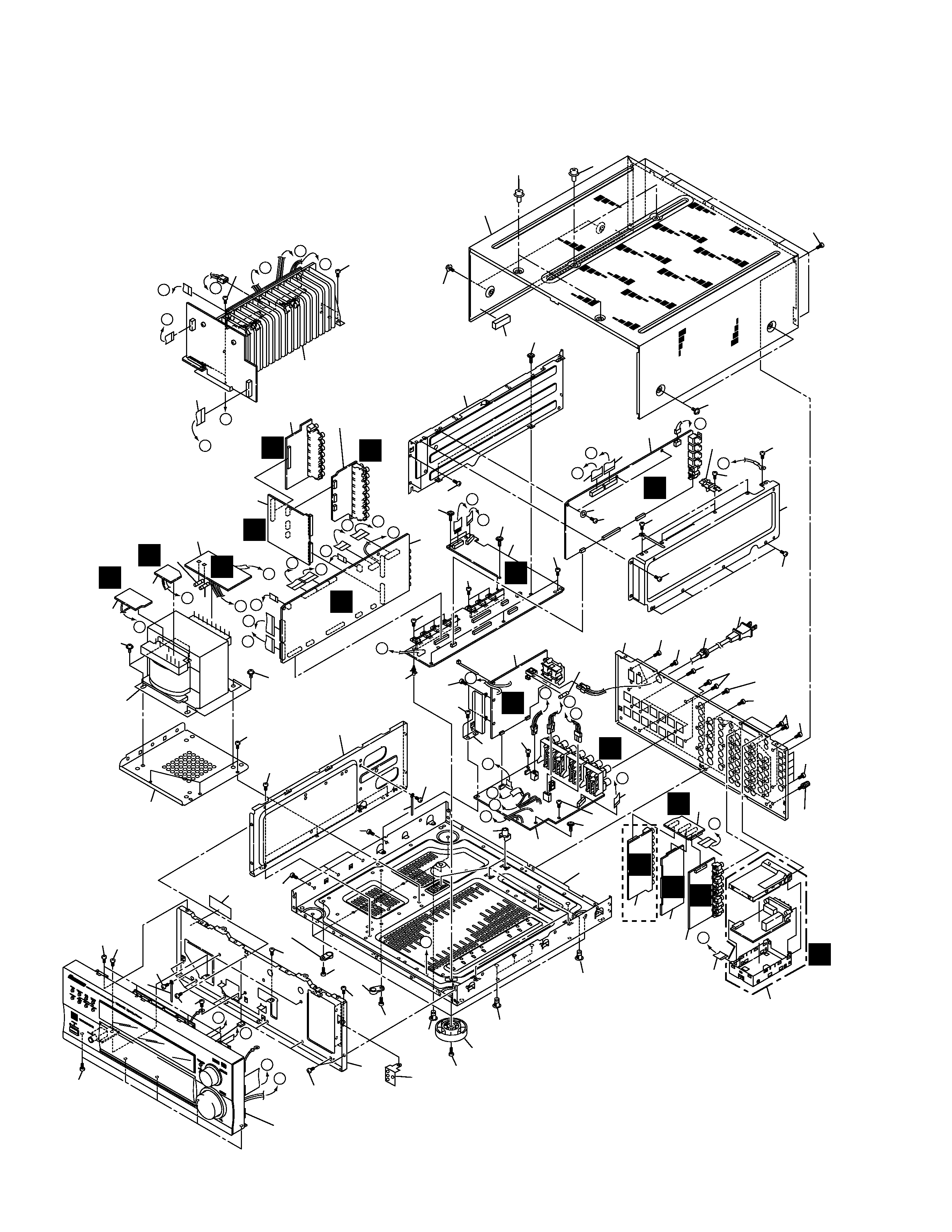
2.2 EXTERIOR SECTION
C
B
F
E
B
P
N
O
Q
R
S
J
H
I
K
L
R
T
P
Q
V
B
T
U
F
S
V
U
O
E
M
C
D
L
A
K
D
G
A
I
H
N
G
J
33
51
51
28
48
22
17
PCB Holder
22
48
48
12
36
47
47
47
47
47
47
47
31
37
47
40
47
45
47
47
47
47
47
35
34
44
47
47
47
47
47
49 47
47
47
29
25
47
45
47
46
45
47
38
15
21
Refer to
"2.3 HEAT SINK SECTION".
47
23
4
6
11
19
14
13
50
50
18
20
5
2 or 3
51
47
Refer to
"2.4 FRONT PANEL SECTION".
B
C
E
N
A
F
G
R
L
Q
H
Y
M
P
O
D
47
47
47
47
47
47
9
24
47
47
48
10
43
30
42
22
7
52
41
47
1
26
49
27
(VSX-35TX
Only)
(VSX-35TX
Only)
(VSX-35TX
Only)
8
16
43
43
39
47
32
47
47
Screw Cover
Screw Cover
47
51
5
VSX-35TX, VSX-33TX
1
FM/AM TUNER Module
AXQ7231
2
EX I/O Assy
See Contrast table (2)
3
5.1CH I/O Assy
See Contrast table (2)
4
INPUT Assy
See Contrast table (2)
5
MAIN CONTROL Assy
See Contrast table (2)
6
A-CONNECTION Assy
See Contrast table (2)
7
COMPOSITE Assy
See Contrast table (2)
8
S VIDEO Assy
See Contrast table (2)
9
V-CONNECTION Assy
See Contrast table (2)
10
SP/PS Assy
See Contrast table (2)
11
TRANS 2-1 Assy
AWX7572
12
REGULATOR Assy
AWX7562
13
TRANS 2-2 Assy
See Contrast table (2)
NSP
14
TRANS 1 Assy
AWX7564
15
PRIMARY Assy
AWX7563
16
COMPONENT Assy
See Contrast table (2)
17
DSP Assy
See Contrast table (2)
18
Power Transformer (T1)
ATS7284
19
Fuse (FU4 : 2.5A)
REK1112
20
Fuse (FU5 : 2.5A)
REK1112
21
Fuse (FU1 : 10A)
VEK1029
22
20P Flexible Cable/60V
ADD7241
23
22P Flexible Cable/60V
ADD7243
24
14P Flexible Cable/60V
ADD7244
25
SE Angle 35
ANG7335
(1) EXTERIOR PARTS LIST
Mark No.
Description
Part No.
Mark No.
Description
Part No.
26
Cord Stopper
CM-22C
27
Power Cord
VDG1075
28
Spacer 35 (3
× 10 × 40)
AEB7210
29
Cushion 8
× 8
AED7046
NSP
30
Under Base
ANA7113
31
Rear Panel
See Contrast table (2)
NSP
32
Panel Stay 35
AND7035
33
Bonnet 35
AZN7835
34
Trans Frame 35
ANG7292
35
Trans Shield 35
ANG7293
36
DSP Shield 35 A
ANG7295
37
DSP Shield 35 B
ANG7296
38
Primary Angle 35
ANG7301
39
Insulator
PNW2766
40
Fiber Washer
VEC1254
41
Earth Terminal
See Contrast table (2)
42
PCB Mold
AMR2534
43
Card Spacer
DNK2769
44
Locking Card Spacer
PNW2917
45
Cord Clamper
RNH-184
46
65 Label
ARW7050
47
Screw
BBZ30P080FZK
48
Screw
IBZ30P150FCC
49
Screw
IBZ30P100FCC
50
Screw
ABA7066
51
Screw
FBT40P080FZK
52
13P Flexible Cable/60V
ADD7242
(2) CONTRAST TABLE
VSX-35TX and VSX-33TX are constructed the same except for the following :
Mark No.
Symbol and Description
Part No.
Remarks
VSX-35TX
VSX-33TX
2
3
4
5
6
7
8
9
10
13
16
17
31
31
41
EX I/O Assy
5.1CH I/O Assy
INPUT Assy
MAIN CONTROL Assy
A-CONNECTION Assy
COMPOSITE Assy
S VIDEO Assy
V-CONNECTION Assy
SP/PS Assy
TRANS 2-2 Assy
COMPONENT Assy
DSP Assy
Rear Panel 35
Rear Panel 33
Earth Terminal
AWX7568
Not used
AWX7573
AWX7560
AWX7566
AWX7581
AWX7580
AWX7567
AWX7571
AWX7565
AWX7582
AWX7561
ANC7910
Not used
AKE-031
Not used
AWX7613
AWX7585
AWX7610
AWX7619
AWX7617
AWX7616
AWX7717
AWX7721
AWX7720
Not used
AWX7611
Not used
ANC7911
Not used