ORDER NO.
PIONEER ELECTRONIC CORPORATION 4-1, Meguro 1-Chome, Meguro-ku, Tokyo 153-8654, Japan
PIONEER ELECTRONICS SERVICE, INC. P.O. Box 1760, Long Beach, CA 90801-1760, U.S.A.
PIONEER ELECTRONIC (EUROPE) N.V. Haven 1087, Keetberglaan 1, 9120 Melsele, Belgium
PIONEER ELECTRONICS ASIACENTRE PTE. LTD. 253 Alexandra Road, #04-01, Singapore 159936
PIONEER ELECTRONIC CORPORATION 1999
RRV2098
T ZZK JAN. 1999 Printed in Japan
¶ Refer to the service manual RRV1911 for VSX-D507S/KUXJI.
THIS MANUAL IS APPLICABLE TO THE FOLLOWING MODEL(S) AND TYPE(S).
Model
VSX-D488
Type
Power Requirement
Remarks
KUXJI
KCXJI
AUDIO/VIDEO MULTI-CHANNEL RECEIVER
VSX-D488
AC120V
AC120V
VSX-D488
2
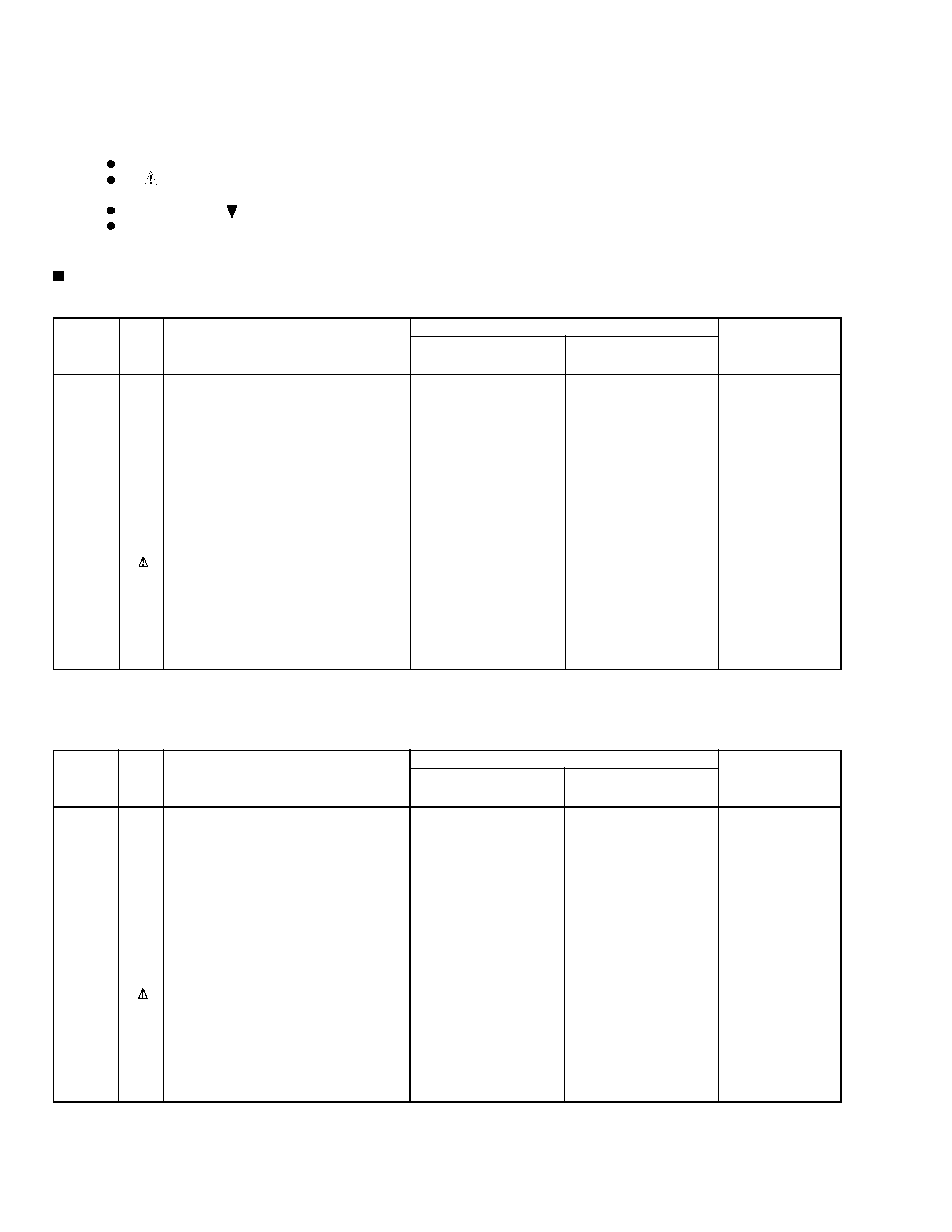
1. CONTRAST OF MISCELLANEOUS PARTS
Parts marked by "NSP" are generally unavailable because they are not in our Master Spare Parts List.
The
mark found on some component parts indicates the importance of the safety factor of the part.
Therefore, when replacing, be sure to use parts of identical designation.
Screws adjacent to
mark on product are used for disassembly.
Reference Nos. indicate the pages and Nos. in the service manual for the base model.
NOTES:
CONTRAST TABLE
VSX-D488/KUXJI and VSX-D507S/KUXJI are constructed the same except for the following :
PACKING
P3- 3
Operating Instructions (English)
ARB7134
ARB7179
P3- 4
NSP
Warranty Card
ARY1051
ARY7023
P3- 5
Remote Control Unit (CU-VSX127)
AXD7158
Not used
P3- 5
Remote Control Unit (CU-VSX154)
Not used
AXD7211
*1
P3-11
Packing Case
AHD7554
AHD7731
P3-13
Sub Instructions (English)
ARH7033
Not used
EXTERIOR SECTION
P5-14
AC Power Cord
PDG1063
PDG1064
P5-19
Rear Panel
ANC7624
ANC7797
FRONT PANEL SECTION
P6-17
Front Panel
AMB7486
AMB7607
P6-19
PIONEER Badge
PAM1755
PAM1776
Part No.
VSX-D507S
/KUXJI
Ref. No.
Symbol and Description
Remarks
Mark
VSX-D488
/KUXJI
VSX-D488/KCXJI and VSX-D507S/KCXJI are constructed the same except for the following :
PACKING
P3- 3
Operating Instructions (English/French)
ARE7165
ARE7203
P3- 4
NSP
Warranty Card
ARY1075
ARY7024
P3- 5
Remote Control Unit (CU-VSX127)
AXD7158
Not used
P3- 5
Remote Control Unit (CU-VSX154)
Not used
AXD7211
*1
P3-11
Packing Case
AHD7601
AHD7731
P3-13
Sub Instructions (English)
ARH7033
Not used
EXTERIOR SECTION
P5-14
AC Power Cord
PDG1063
PDG1064
P5-19
Rear Panel
ANC7670
ANC7798
FRONT PANEL SECTION
P6-17
Front Panel
AMB7486
AMB7607
P6-19
PIONEER Badge
PAM1755
PAM1776
Part No.
VSX-D507S
/KCXJI
Ref. No.
Symbol and Description
Remarks
Mark
VSX-D488
/KCXJI
*1 : refer to "2. REMOTE CONTROL UNIT [CU-VSX154 (AXD7211)]".
*1 : refer to "2. REMOTE CONTROL UNIT [CU-VSX154 (AXD7211)]".
VSX-D488
3
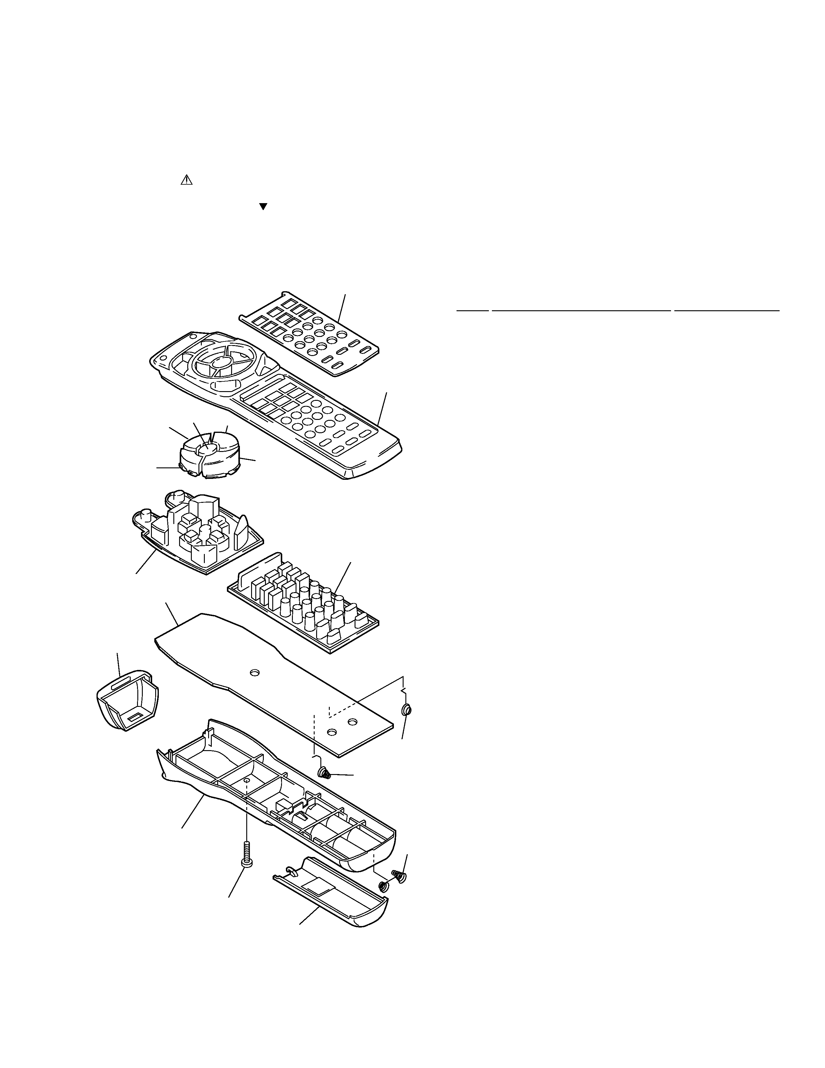
2. REMOTE CONTROL UNIT [CU-VSX154 (AXD7211)]
2.1 EXPLODED VIEWS AND PARTS LIST
· Parts List
Mark No.
Description
Part No.
1
Filter
AZA7152
2
Name Plate
AZA7323
3
Rubber Sheet (A)
AZA7324
4
Rubber Sheet (B)
AZA7322
5
Spring (+)
AZB7049
6
Spring ()
AZB7050
7
Spring
AZB7051
8
Screw
AZB7052
9
Remo-con Case (A)
AZN7766
10
Remo-con Case (B)
AZN7326
11
Battery Cover
AZN7327
12
Main Key (FF)
AZN7666
13
Main Key (STOP)
AZN7767
14
Main Key (REV)
AZN7665
15
Main Key (PAUSE)
AZN7768
16
Main Key (PLAY)
AZN7765
NSP
17
PCB
AZW7248
2
9
13
12
16
15
14
3
17
1
10
8
11
7
6
5
4
NOTES:
· Parts marked by "NSP" are generally unavailable because they are not in our Master Spare Parts List.
· The mark found on some component parts indicates the importance of the safety factor of the part.
Therefore, when replacing, be sure to use parts of identical designation.
· Screws adjacent to mark on the product are used for disassembly.
VSX-D488
4
A
B
C
D
1
23
4
12
3
4
8
16
24
32
40
7
15
23
31
39
6
14
22
30
38
5
13
21
29
37
4
12
20
28
36
3
11
19
27
35
2
10
18
26
34
1
9
17
25
33
No.
12
8
27
26
25
24
23
22
21
20
19
18
17
16
15
3.0V
T5
T4
T3
T1
X1
4.0MHz
T2
D2
RLS-73
KEY
No.
R3
47
R7
100k
R6
100k
R1
1.8
R2
220
IC1
AZC7284
R18
0
Q4
Q3
Q2
R5
100k
R10
R13
R16
R15
R14
R12
R11
R9
R8
D11
D14
D17
D1
SE303A-C
C3
1/50
C4
1/50
Q1
2SC3265
D16
D15
D13
D12
D10
D9
Q2
-
Q4
:
RN4605
×3
D9
-
D17
:
CL-230HR-CD
×9
R8
-
R16
:
240
×9
P0D1
P0D0
P0C3
P0C2
P0C1
P0C0
P0B3
P0B2
P0B1
P0B0
P0A3
P0A2
P0A1
P0A0
2
3
4
5
6
7
8
9
10
11
12
13
14
P0D2
P0D3
P0D3
P0D2
P0D1
P0E3
P0E2
P0E0
INT
P0E0
P0E1
P0E2
P0E3
REM
VDD
XOUT
XIN
GND
RESET
WDOUT
C1
220/6.3
C2
47/10
K01
:
AMP
(POWER)
K02
:
TV
(POWER)
K03
:
MUTING
K04
:
POWER
K05
:
TV
FUNC.
K06
:
VOL.-
K07
:
VOL.+
K08
:
K09
:
K10
:
K11
:
K12
:
ENT.
K13
:
CH-
K14
:
CH+
K15
:
DVD
K16
:
LD/SAT
K17
:
CD
K18
:
VCR1
K19
:
TUNER
K20
:
TV
CONTROL
K21
:
No
key
K22
:
SURROUND
K23
:
No
key
K24
:
1
K25
:
2
K26
:
3
K27
:
4
K28
:
5
K29
:
6
K30
:
7
K31
:
8
K32
:
9
K33
:
10
(0)
K34
:
11
(+10)
K35
:
12
(DISC)
K36
:
No
key
K37
:
FUNCTION
K38
:
MODE
CHECK
K39
:
No
key
K40
:
COMMANDER
SET
UP
SWITCHES
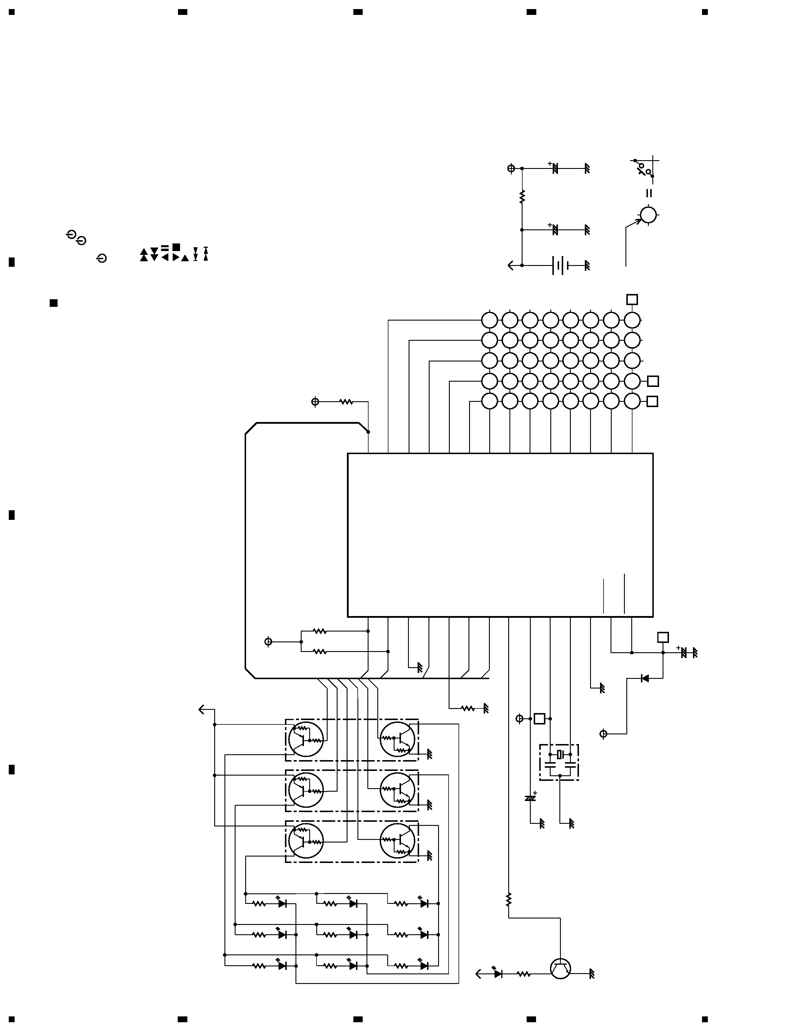
Note : When ordering service parts, be sure to refer to "EXPLODED VIEWS and PARTS LIST" or "PCB PARTS LIST"
2.2 SCHEMATIC DIAGRAM
VSX-D488
5
A
B
C
D
1
23
4
1
2
3
4
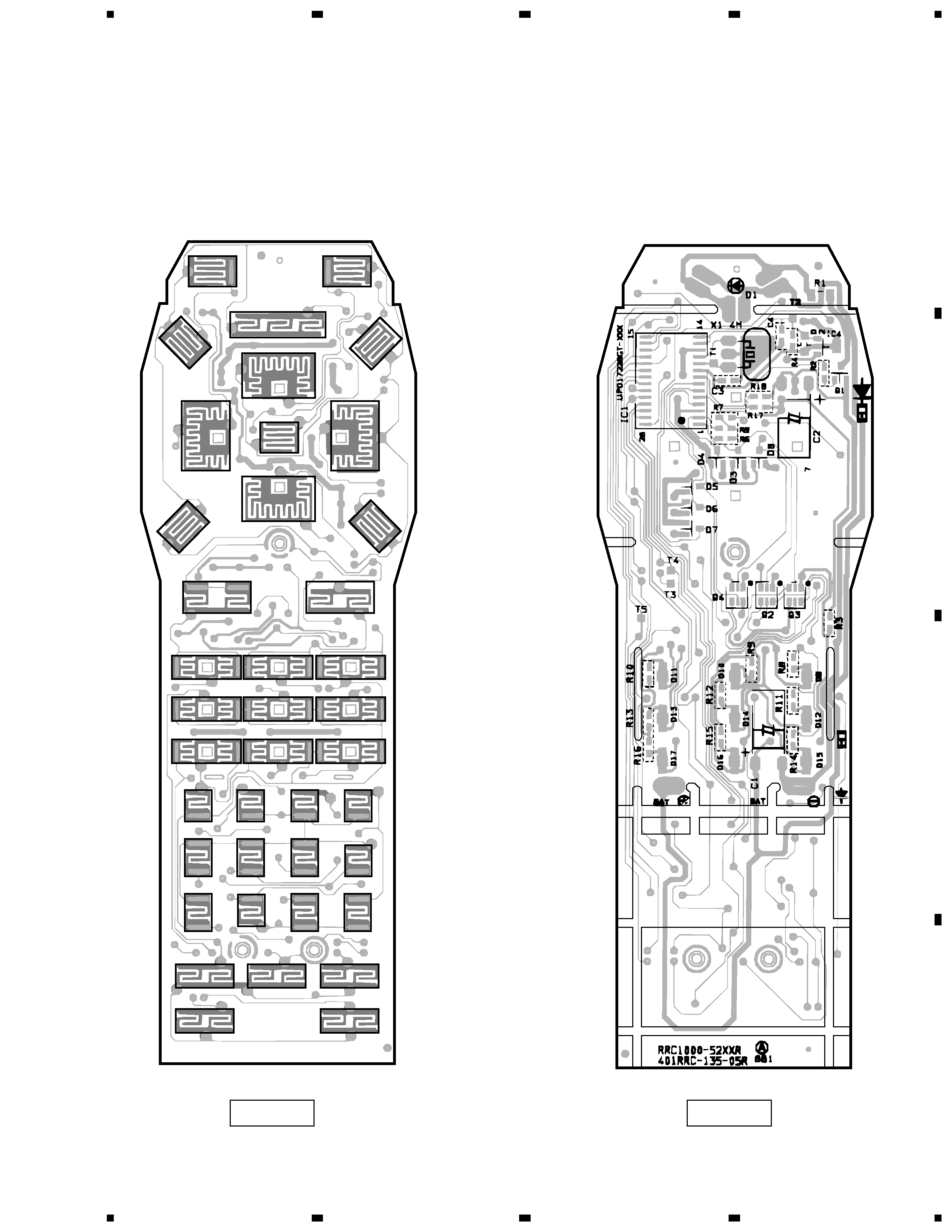
2.3 PCB DIAGRAM
K01
K04
K10
K12
K11
K09
K03
K07
K05
K06
K13
K15
K02
K08
K14
K16
K17
K18
K24
K20
K19
K21
K37
K36
K38
K39
K40
K22
K23
K25
K26
K27
K33
K28
K29
K30
K32
K34
K35
K31
SIDE A
SIDE B