PIONEER CORPORATION 4-1, Meguro 1-chome, Meguro-ku, Tokyo 153-8654, Japan
PIONEER ELECTRONICS (USA) INC. P.O. Box 1760, Long Beach, CA 90801-1760, U.S.A.
PIONEER EUROPE NV Haven 1087, Keetberglaan 1, 9120 Melsele, Belgium
PIONEER ELECTRONICS ASIACENTRE PTE. LTD. 253 Alexandra Road, #04-01, Singapore 159936
PIONEER CORPORATION 2001
c
ORDER NO.
RRV2524
1. SAFETY INFORMATION ...................................... 2
2. EXPLODED VIEWS AND PARTS LIST ............... 3
3. BLOCK DIAGRAM AND SCHEMATIC DIAGRAM ..... 8
4. PCB CONNECTION DIAGRAM ......................... 32
5. PCB PARTS LIST ............................................... 46
6. ADJUSTMENT .................................................... 50
CONTENTS
7. GENERAL INFORMATION ................................ 51
7.1 DIAGNOSIS .................................................. 51
7.1.1 Test Mode ................................................ 51
7.1.2 Protection of the Amplifier Line ............... 52
7.1.3 Operation of the Fan-Control Line ........... 53
7.1.4 Specifications of Speaker Detection ........ 54
7.1.5 Timing Chart ............................................ 55
7.2 PARTS .......................................................... 56
7.2.1 IC ............................................................ 56
7.2.2 DISPLAY ................................................. 62
8. PANEL FACILITIES AND SPECIFICATIONS ....... 64
T ZZR SEPT. 2001 Printed in Japan
AUDIO/VIDEO MULTI-CHANNEL RECEIVER
VSX-C300
STANDBY
PHONES
VIDEO
AUDIO
DIGITAL IN
FRONT INPUT
INPUT SIGNAL
DIGITAL
2DIGITAL
2PROLOGIC
DTS
VIRTUAL
PHONES
SURR
STEREO
AUDIO/VIDEO MULTI-CHANNEL RECEIVER VSX-C300
DVD
TV/SAT
VCR
FRONT
TUNER
MASTER
VOLUME
DOWN
UP
MULTI ch
LR
OFF
ON
THIS MANUAL IS APPLICABLE TO THE FOLLOWING MODEL(S) AND TYPE(S).
Remarks
Power Requirement
Type
Model
VSX-C300
KUXJI/CA
AC120V
2
VSX-C300
1. SAFETY INFORMATION
This service manual is intended for qualified service technicians ; it is not meant for the casual do-it-
yourselfer. Qualified technicians have the necessary test equipment and tools, and have been trained
to properly and safely repair complex products such as those covered by this manual.
Improperly performed repairs can adversely affect the safety and reliability of the product and may
void the warranty. If you are not qualified to perform the repair of this product properly and safely, you
should not risk trying to do so and refer the repair to a qualified service technician.
WARNING
This product contains lead in solder and certain electrical parts contain chemicals which are known to the state of California to cause
cancer, birth defects or other reproductive harm.
Health & Safety Code Section 25249.6 Proposition 65
NOTICE
(FOR CANADIAN MODEL ONLY)
Fuse symbols
(fast operating fuse) and/or
(slow operating fuse) on PCB indicate that replacement parts must
be of identical designation.
REMARQUE
(POUR MODÈLE CANADIEN SEULEMENT)
Les symboles de fusible
(fusible de type rapide) et/ou
(fusible de type lent) sur CCI indiquent que les pièces
de remplacement doivent avoir la même désignation.
ANY MEASUREMENTS NOT WITHIN THE LIMITS
OUTLINED ABOVE ARE INDICATIVE OF A POTENTIAL
SHOCK HAZARD AND MUST BE CORRECTED BEFORE
RETURNING THE APPLIANCE TO THE CUSTOMER.
2. PRODUCT SAFETY NOTICE
Many electrical and mechanical parts in the appliance
have special safety related characteristics. These are
often not evident from visual inspection nor the protection
afforded by them necessarily can be obtained by using
replacement components rated for voltage, wattage, etc.
Replacement parts which have these special safety
characteristics are identified in this Service Manual.
Electrical components having such features are identified
by marking with a
on the schematics and on the parts list
in this Service Manual.
The use of a substitute replacement component which does
not have the same safety characteristics as the PIONEER
recommended replacement one, shown in the parts list in
this Service Manual, may create shock, fire, or other hazards.
Product Safety is continuously under review and new
instructions are issued from time to time. For the latest
information, always consult the current PIONEER Service
Manual. A subscription to, or additional copies of, PIONEER
Service Manual may be obtained at a nominal charge from
PIONEER.
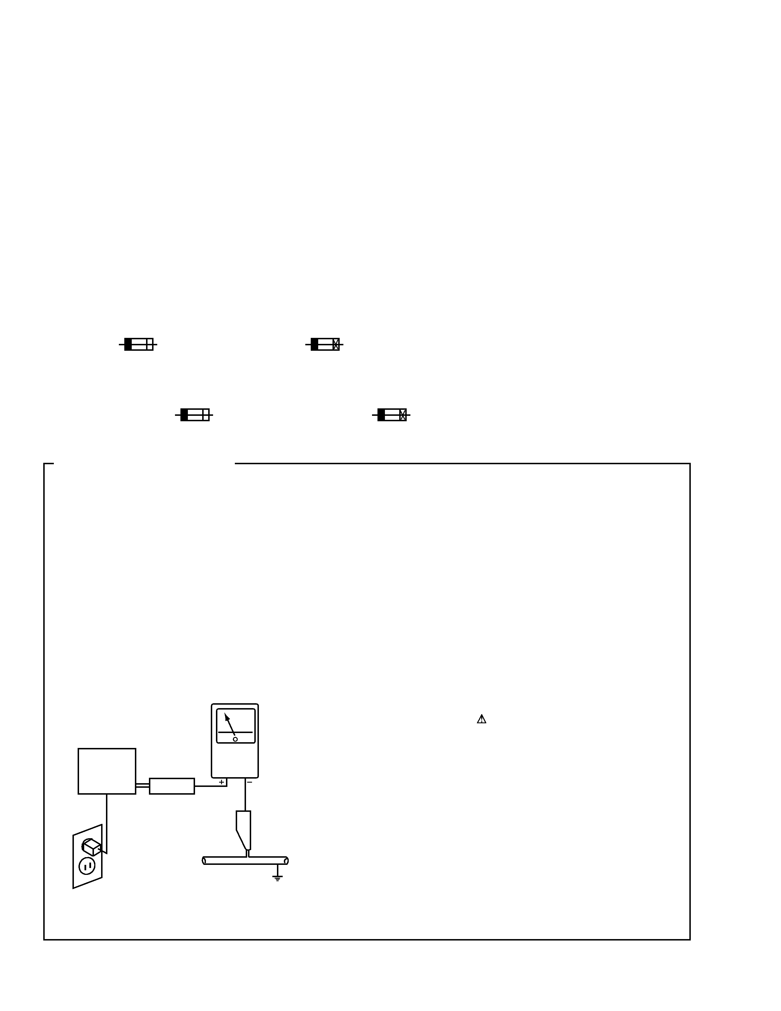
1. SAFETY PRECAUTIONS
The following check should be performed for the
continued protection of the customer and service
technician.
LEAKAGE CURRENT CHECK
Measure leakage current to a known earth ground (water
pipe, conduit, etc.) by connecting a leakage current tester
such as Simpson Model 229-2 or equivalent between the
earth ground and all exposed metal parts of the appliance
(input/output terminals, screwheads, metal overlays, control
shaft, etc.). Plug the AC line cord of the appliance directly
into a 120V AC 60Hz outlet and turn the AC power switch
on. Any current measured must not exceed 0.5mA.
(FOR USA MODEL ONLY)
Leakage
current
tester
Reading should
not be above
0.5mA
Device
under
test
Test all
exposed metal
surfaces
Also test with
plug reversed
(Using AC adapter
plug as required)
Earth
ground
AC Leakage Test
3
VSX-C300
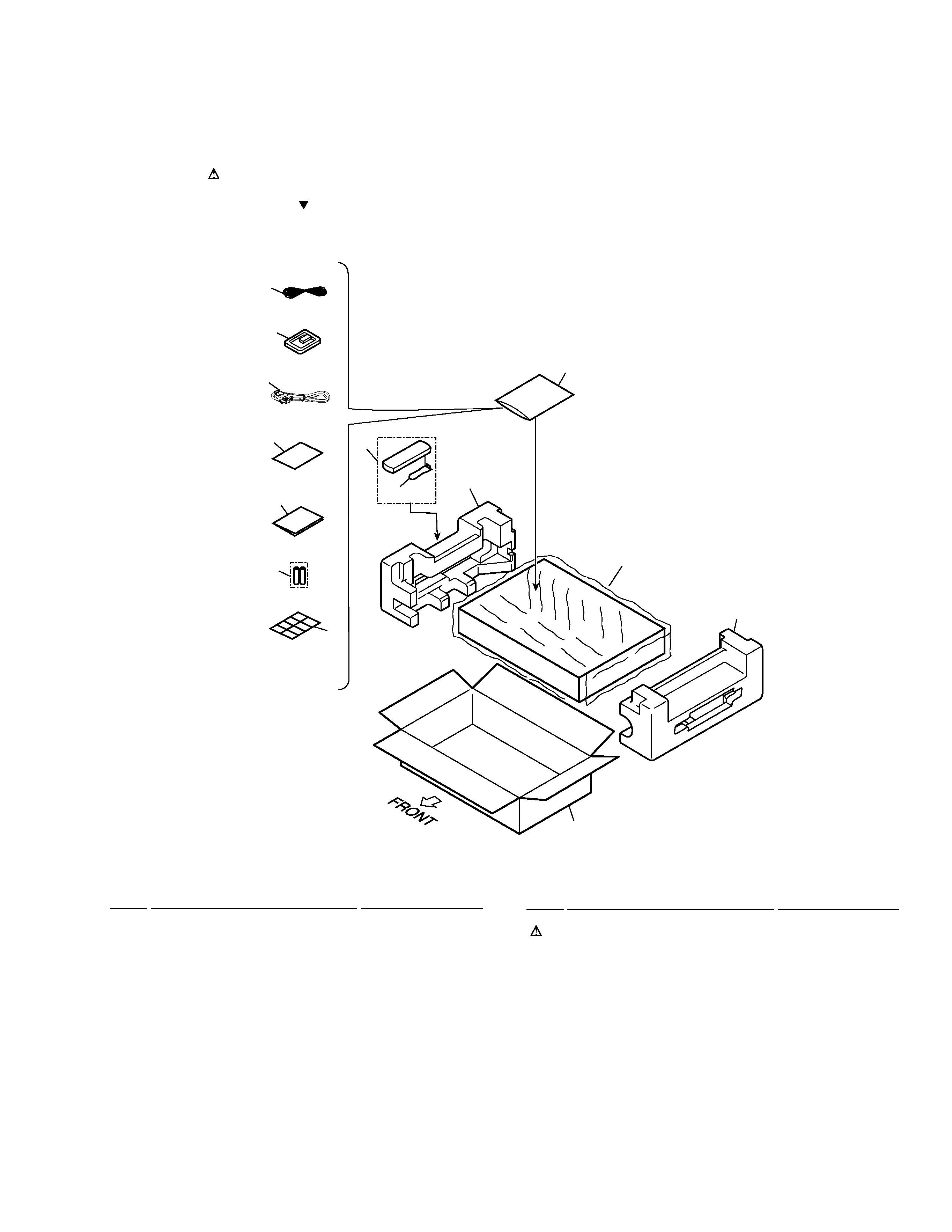
2.1 PACKING
1
FM Wire Antenna
ADH7004
2
AM Loop Antenna
ATB7009
NSP
3
Polyethylene Bag
Z21-038
(0.03
× 230 × 340)
NSP
4
Warranty Card
ARY7045
5
Remote Control Unit
AXD7310
6
Battery Cover
AZA7378
NSP
7
Dry Cell Battery (R6P, AA)
VEM-013
8
Left Pad
AHA7349
9
Right Pad
AHA7350
10
Packing Sheet
AHG7015
11
Packing Case
AHD8010
12
Operating Instructions
ARB7248
(English)
÷ PACKING PARTS LIST
Mark No.
Description
Part No.
2. EXPLODED VIEWS AND PARTS LIST
NOTES:
· Parts marked by "NSP" are generally unavailable because they are not in our Master Spare Parts List.
· The mark found on some component parts indicates the importance of the safety factor of the part.
Therefore, when replacing, be sure to use parts of identical designation.
· Screws adjacent to mark on the product are used for disassembly.
4
12
7
3
8
9
5
10
11
6
14
2
13
1
13
AC Power Cord
ADG7022
14
Cable Label
ARW7145
Mark No.
Description
Part No.
4
VSX-C300
A
A
B
B
C
C
D
E
D
F
F
H
I
I
H
G
G
24
36
33
36
36
36
36
36
36
36
36
37
36
36
28
29
15
29
1
2
5
27
12
13
47
14
16
20
E
22
17
4
3
8
6
36
11
36
36
33
43
43
43
36
48
10
36
36
36
40
Refer to
"2.3 FRONT PANEL SECTION".
26
30
22
38
42
36
31
23
44
E
A
M
J
B
C
D
L
36
21
32
34
41
45
51
52
45
45
25
54
39
39
38
7
19
45
49
18
46
50
53
53
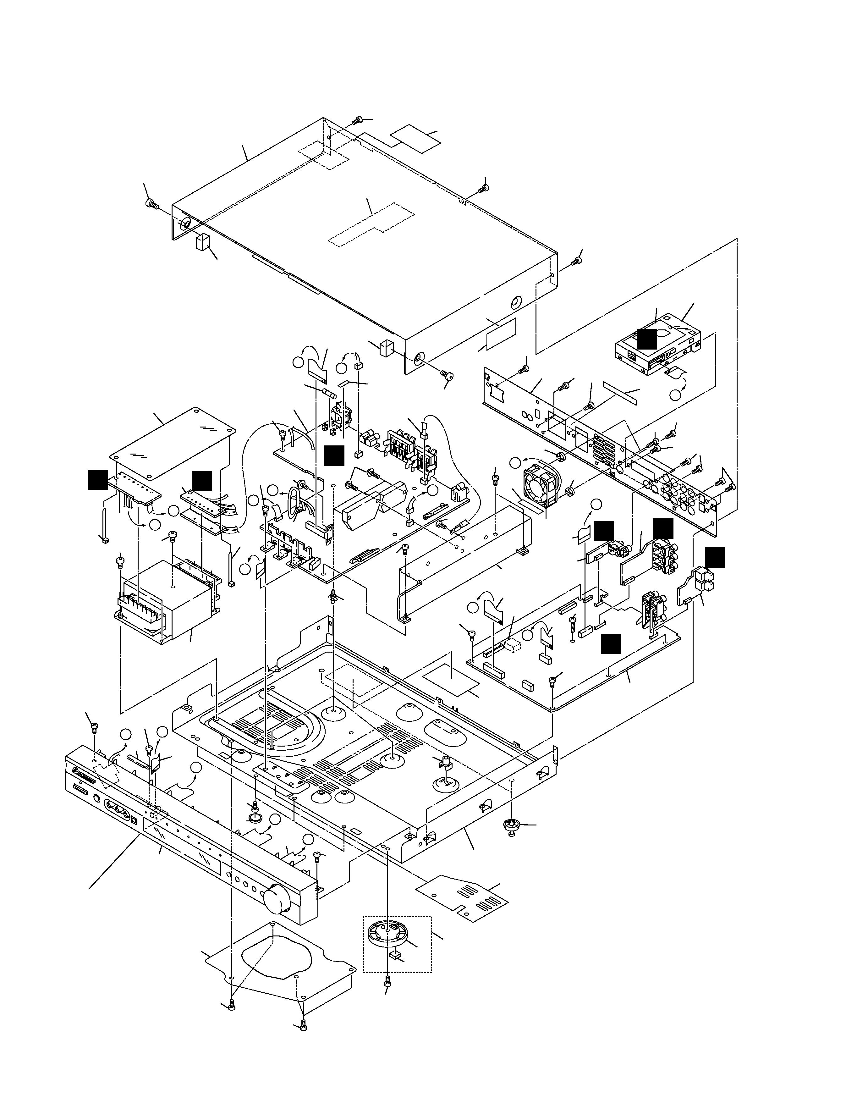
2.2 EXTERIOR SECTION

5
VSX-C300
1
DSP ASSY
AWX7937
2
2P - JACK ASSY
AWX7926
3
POWER ASSY
AWX7910
4
VIDEO ASSY
AWX7928
5
OPT - IN ASSY
AWX7908
6
TRANS 2 Assy
AWX7907
7
FM/AM TUNER MODULE
AXQ7231
NSP
8
TRANS 1 Assy
AWX7906
9
· · · · ·
10
Power Transformer (AC120V)
ATS7317
11
Fuse (FU1 : 2.5A)
REK1112
12
FFC (J804 : 13P/180 BD 60V)
ADD7242
(DSP CN803
TUNER CN201)
13
FFC (J1702 : 23P/180 BD 60V) ADD7293
(DSP CN1702
FRONT CN4202)
14
FFC (J4201 : 23P/200 BD 60V) ADD7293
(POWER CN303
FRONT CN4201)
15
FFC (J4101 : 11P/100 BD 60V) ADD7336
(POWER CN304
FRONT INPUT CN4101)
16
Thermistor
AEX7004
(POWER CN306
TH9014)
17
Trans Shield Barrier
AEC7380
18
REG. Cover
AEC7384
19
Tuner Barrier
AEC7383
20
Leg Assy
REC-434
21
Insulator 50
AMR7363
22
FFC (J803 : 7P/150 BD 60V)
ADD7292
(DSP CN804
FRONT CN203)
NSP
23
Under Base
ANA7129
24
Rear Panel
ANC8017
25
Bonnet Case S (Box)
AZN7886
26
PCB Support
AEC7365
27
DC Fan Motor
AXM7017
NSP
28
Heat Sink HL
ANH7144
29
Damper BK
AEB7231
NSP
30
Trans Stabilizer
ANG7362
÷ EXTERIOR SECTION PARTS LIST
Mark No.
Description
Part No.
Mark No.
Description
Part No.
31
Rubber Cushion
AEB7235
32
Insulator 50 Assy
AMR7379
33
Screw With Washer
ABA7080
34
PCB Mold
AMR2534
35
· · · · ·
36
Screw
BBZ30P080FZK
37
Screw
BBZ30P140FMC
38
Screw
BBZ40P080FNI
39
Screw
BBZ40P060FCC
40
Front Panel Assy
AMB7778
41
Dolby DTS. Label
ARW7136
42
Speaker Label E
AAX7870
43
Binder
ZCABK1
44
Screw (3x11.5)
ABA7071
45
Screw
BBZ30P080FNI
46
Cord Clamper
RNH-184
47
Cushion H11
AEB7239
48
Damper Cushion
AED7055
49
Cushion Circle 16S
AED7054
50
Fuse Card
AAX2344
51
65 Label
ARW7050
52
Caution Label
ARW7143
53
Rubber Cushion
AEB7235
54
Support PCB
ANZ7133