ORDER NO.
PIONEER CORPORATION 4-1, Meguro 1-chome, Meguro-ku, Tokyo 153-8654, Japan
PIONEER ELECTRONICS (USA) INC. P.O. Box 1760, Long Beach, CA 90801-1760, U.S.A.
PIONEER EUROPE NV Haven 1087, Keetberglaan 1, 9120 Melsele, Belgium
PIONEER ELECTRONICS ASIACENTRE PTE. LTD. 253 Alexandra Road, #04-01, Singapore 159936
PIONEER CORPORATION 2003
VSX-AX5i-S
RRV2801
AUDIO/VIDEO MULTI-CHANNEL RECEIVER
VSX-AX5i-S
VSX-AX3-S
VSX-AX3-K
THIS MANUAL IS APPLICABLE TO THE FOLLOWING MODEL(S) AND TYPE(S).
*:Alter the wiring of the power-supply block at the primary winding of Power transformer referring to the Line Voltage Selection
described in Service Manual.
Model
Type
Power Requirement
The voltage can be converted by the
following method.
VSX-AX5i-S
HYXJI
AC220-230V
AC240V, *
VSX-AX3-S
HYXJI
AC220-230V
AC240V, *
VSX-AX3-K
HYXJI
AC220-230V
AC240V, *
For details, refer to "Important symbols for good services".
T-ZZE JULY 2003 printed in Japan
VSX-AX5i-S
2
1234
123
4
C
D
F
A
B
E
SAFTY INFORMATION
This service manual is intended for qualified service technicians; it is not meant for the casual
do-it-yourselfer. Qualified technicians have the necessary test equipment and tools, and have been
trained to properly and safely repair complex products such as those covered by this manual.
Improperly performed repairs can adversely affect the safety and reliability of the product and may
void the warranty. If you are not qualified to perform the repair of this product properly and safely, you
should not risk trying to do so and refer the repair to a qualified service technician.
WARNING
This product contains lead in solder and cer tain electrical par ts contain chemicals which are known to the state of California to
cause cancer, bir th defects or other reproductive harm.
Health & Safety Code Section 25249.6 Proposition 65
NOTICE
(FOR CANADIAN MODEL ONLY)
Fuse symbols
(fast operating fuse)
and/or
(slow operating fuse) on PCB indicate that replacement
parts must be of identical designation.
REMARQUE
(POUR MODÈLE CANADIEN SEULEMENT)
Les symboles de fusible
(fusible de type rapide)
et/ou
(fusible de type lent) sur CCI indiquent que
les pièces de remplacement doivent avoir la même désignation.
ANY MEASUREMENTS NOT WITHIN THE
LIMITS OUTLINED ABOVE ARE INDICATIVE
OF A POTENTIAL SHOCK HAZARD AND
MUST BE CORRECTED BEFORE RETURN-
ING THE APPLIANCE TO THE CUSTOMER.
2. PRODUCT SAFETY NOTICE
Many electrical and mechanical parts in the appliance
have special safety related character istics. These are
often not evident
from visual
inspection nor the
protection afforded by them necessarily can be obtained
by using replacement components rated for voltage,
wattage, etc. Replacement par ts which have these
special safety character istics are identified in this
Service Manual.
Electr ical components having such features are
identified by marking with a
on the schematics and
on the parts list in this Service Manual.
The use of a substitute replacement component which
does not have the same safety characteristics as the
PIONEER recommended replacement one, shown in the
parts list in this Service Manual, may create shock, fire,
or other hazards.
Product Safety is continuously under review and new
instructions are issued from time to time. For the latest
infor mation, always consult the current PIONEER
Ser vice Manual. A subscription to, or
additional copies
of, PIONEER Ser vice Manual may be obtained at a
nominal charge from PIONEER.
(FOR USA MODEL ONLY)
1. SAFETY PRECAUTIONS
The following check should be perfor med for the
continued protection of the customer and ser vice
technician.
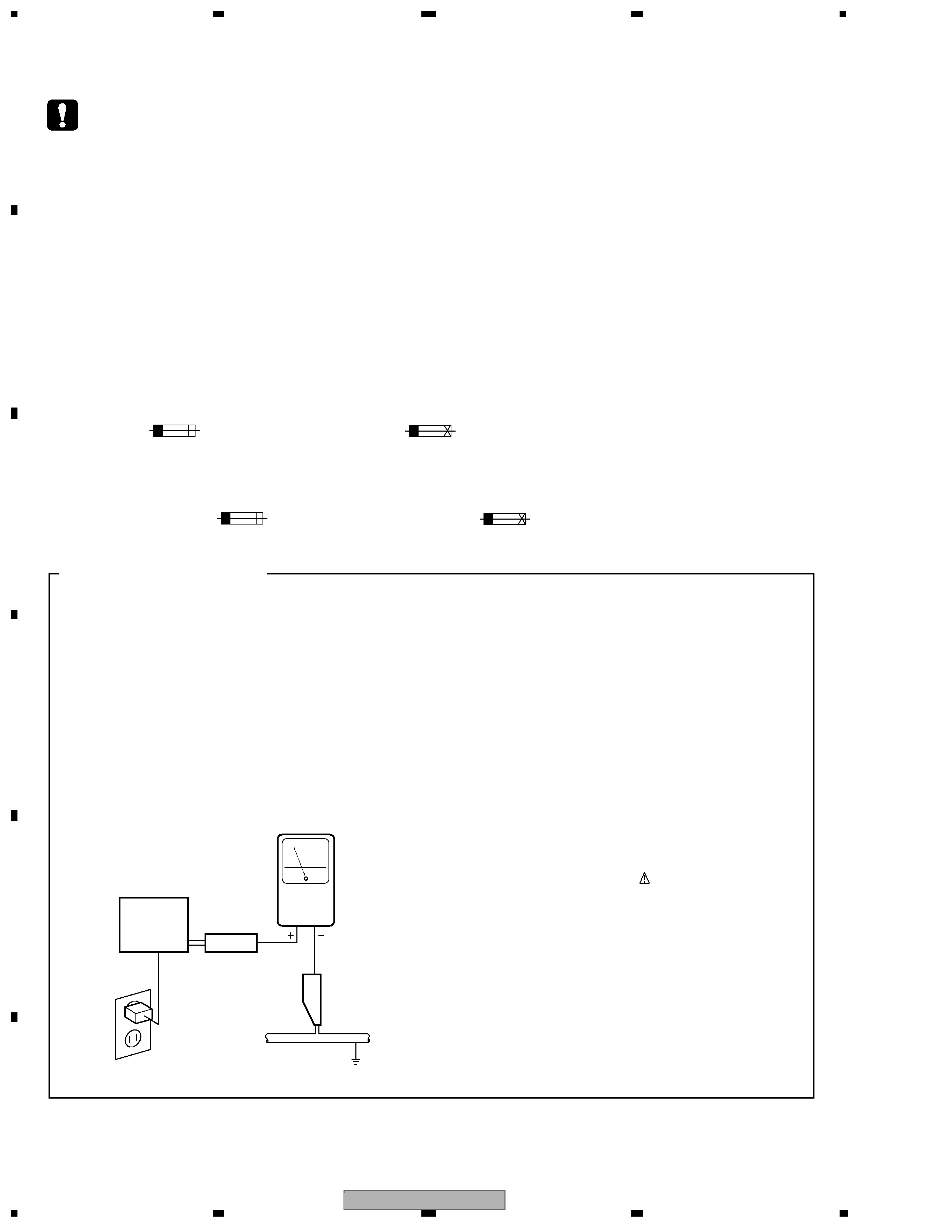
LEAKAGE CURRENT CHECK
Measure leakage current to a known ear th ground
(water pipe, conduit, etc.) by connecting a leakage
current tester such as Simpson Model 229-2 or
equivalent between the ear th ground and all exposed
metal par ts of the appliance (input/output ter minals,
screwheads, metal overlays, control shaft, etc.). Plug
the AC line cord of the appliance directly into a 120V
AC 60 Hz outlet and turn the AC power switch on. Any
current measured must not exceed 0.5 mA.
Device
under
test
Leakage
current
tester
Earth
ground
Reading should
not be above
0.5 mA
Also test with
plug reversed
(Using AC adapter
plug as required)
Test all
exposed metal
surfaces
AC Leakage Test
VSX-AX5i-S
3
5
678
56
7
8
C
D
F
A
B
E
CONTENTS
SAFTY INFORMATION ........................................................................................................................................2
1. SPECIFICATIONS .............................................................................................................................................5
2. EXPLODED VIEWS AND PARTS LIST.............................................................................................................8
2.1 PACKING ....................................................................................................................................................8
2.2 EXTERIOR SECTION ..............................................................................................................................10
2.3 REAR PANEL SECTION ..........................................................................................................................12
2.4 HEAT SINK SECTION ..............................................................................................................................14
2.5 FRONT PANEL SECTION ........................................................................................................................16
3. BLOCK DIAGRAM AND SCHEMATIC DIAGRAM ..........................................................................................18
3.1 BLOCK DIAGRAM ....................................................................................................................................18
3.1.1 AUDIO BLOCK DIAGRAM.....................................................................................................................18
3.1.2 DSP BLOCK DIAGRAM ........................................................................................................................20
3.1.3 1394 BLOCK DIAGRAM ........................................................................................................................22
3.1.4 POWER AMP BLOCK DIAGRAM..........................................................................................................23
3.1.5 VIDEO BLOCK DIAGRAM.....................................................................................................................24
3.2 OVERALL WIRING DIAGRAM .................................................................................................................26
3.3 7.1 CH I/O, V-AUDIO, FRONT IN and OPTICAL IN ASSYS.....................................................................28
3.4 INPUT CONNECT ASSY..........................................................................................................................30
3.5 COAXIAL IN ASSY ...................................................................................................................................32
3.6 COMPONENT ASSY................................................................................................................................34
3.7 VIDEO ASSY ............................................................................................................................................36
3.8 MAIN CONTROL ASSY (1/3) ...................................................................................................................38
3.9 MAIN CONTROL ASSY (2/3) ...................................................................................................................40
3.10 MAIN CONTROL ASSY (3/3) .................................................................................................................42
3.11 MIC & F.OPT IN, MIC AMP and DSP CONNECTION ASSYS ...............................................................44
3.12 POWER AMP IN, FAN CONNECTION and FAN DRIVE ASSYS...........................................................46
3.13 DSP ASSY (1/2) .....................................................................................................................................48
3.14 DSP ASSY (2/2) .....................................................................................................................................50
3.15 1394 ASSY (1/2) (VSX-AX5i-S ONLY) ...................................................................................................52
3.16 1394 ASSY (2/2) (VSX-AX5i-S ONLY) ...................................................................................................54
3.17 DISPLAY ASSY ......................................................................................................................................56
3.18 VOLUME, MECHA SW, MULTI JOG and HEADPHONE ASSYS...........................................................58
[ Important symbols for good services ]
In this manual, the symbols shown-below indicate that adjustments, settings or cleaning should be made securely.
When you find the procedures bearing any of the symbols, be sure to fulfill them:
2. Adjustments
To keep the original performances of the product, optimum adjustments or specification confirmation is indispensable.
In accordance with the procedures or instructions described in this manual, adjustments should be performed.
3. Cleaning
For optical pickups, tape-deck heads, lenses and mirrors used in projection monitors, and other parts requiring cleaning,
proper cleaning should be performed to restore their performances.
5. Lubricants, glues, and replacement parts
Appropriately applying grease or glue can maintain the product performances. But improper lubrication or applying
glue may lead to failures or troubles in the product. By following the instructions in this manual, be sure to apply the
prescribed grease or glue to proper portions by the appropriate amount.For replacement parts or tools, the prescribed
ones should be used.
4. Shipping mode and shipping screws
To protect the product from damages or failures that may be caused during transit, the shipping mode should be set or
the shipping screws should be installed before shipping out in accordance with this manual, if necessary.
1. Product safety
You should conform to the regulations governing the product (safety, radio and noise, and other regulations), and
should keep the safety during servicing by following the safety instructions described in this manual.

VSX-AX5i-S
4
1234
123
4
C
D
F
A
B
E
3.19 POWER AMP-L ASSY ........................................................................................................................... 60
3.20 POWER AMP-R and POWER AMP-C ASSYS ...................................................................................... 62
3.21 REGULATOR ASSY............................................................................................................................... 64
3.22 SP/PS, DIODE, TRANS 2-1 and VH TR ASSYS....................................................................................66
3.23 TRANS 2-2, TRANS 1 and PRIMARY ASSYS.......................................................................................68
3.24 FM/AM TUNER MODULE ...................................................................................................................... 70
4. PCB CONNECTION DIAGRAM ..................................................................................................................... 72
4.1 7.1CH I/O ASSY ...................................................................................................................................... 73
4.2 V-AUDIO IN ASSY.................................................................................................................................... 75
4.3 FRONT IN and OPTICAL IN ASSYS ....................................................................................................... 76
4.4 COAXIAL IN ASSY .................................................................................................................................. 77
4.5 INPUT CONNECT ASSY ......................................................................................................................... 78
4.6 COMPONENT ASSY ............................................................................................................................... 80
4.7 VIDEO ASSY ........................................................................................................................................... 81
4.8 MAIN CONTROL ASSY ........................................................................................................................... 82
4.9 MIC & F. OPT IN, MIC AMP and DSP CONNECTION ASSYS ............................................................... 86
4.10 POWER AMP IN ASSY.......................................................................................................................... 88
4.11 FAN CONNECTION ASSY .................................................................................................................... 90
4.12 FAN DRIVE ASSY.................................................................................................................................. 91
4.13 DSP ASSY ............................................................................................................................................. 92
4.14 DISPLAY ASSY...................................................................................................................................... 94
4.15 VOLUME, MECHA SW, MULTI JOG and HEADPHONE ASSYS .......................................................... 98
4.16 POWER AMP L and POWER AMP C ASSYS ..................................................................................... 100
4.17 POWER AMP R ASSY......................................................................................................................... 108
4.18 REGULATOR ASSY............................................................................................................................. 116
4.19 SP/PS ASSY ........................................................................................................................................ 124
4.20 DIODE, TRANS 2-1 and VH TR ASSYS .............................................................................................. 126
4.21 TRANS 2-2, TRANS 1 and PRIMARY ASSYS..................................................................................... 128
4.22 1394 ASSY (VSX-AX5i-S ONLY) ......................................................................................................... 132
4.23 FM/AM TUNER MODULE .................................................................................................................... 133
5. PCB PARTS LIST ......................................................................................................................................... 134
6. ADJUSTMENT ............................................................................................................................................. 147
7. GENERAL INFORMATION ........................................................................................................................... 148
7.1 DIAGNOSIS ........................................................................................................................................... 148
7.1.1 PROTECTION CIRCUIT CONTROL SPECIFICATION ...................................................................... 148
7.1.2 DIAGNOSTICS OF AMPLIFIER SECTION ........................................................................................ 150
7.1.3 TROUBLE SHOOTING ....................................................................................................................... 151
7.1.4 DISASSEMBLY ................................................................................................................................... 156
7.2 PARTS.................................................................................................................................................... 159
7.2.1 IC ........................................................................................................................................................ 159
7.2.2 DISPLAY ............................................................................................................................................. 173
7.3 CLEANING............................................................................................................................................. 175
7.4 REMOTE CONTROL UNIT .................................................................................................................... 176
8. PANEL FACILITIES ...................................................................................................................................... 177

VSX-AX5i-S
5
5
678
56
7
8
C
D
F
A
B
E
1. SPECIFICATIONS
· Lucasfilm and THX are trademarks or registered trademarks of Lucasfilm, Ltd. and TM. Surround EX is a jointly developed
technology of THX and Dolby Laboratories, and is a trademark of Dolby Laboratories. All rights reserved. Used under
authorization.
· Manufactured under license from Dolby Laboratories. "Dolby", "Pro Logic", "Surround EX" and double-D symbol
are trademarks of Dolby Laboratories.
· "DTS", "DTS-ES Extended Surround" and "Neo:6" are trademarks of Digital Theater Systems, Inc.
Video Section (Composite)
Input (Sensitivity/Impedance)
LINE.................................................................... 1 Vp-p/75
Output (Level/Impedance)
LINE.................................................................... 1 Vp-p/75
Frequency Response
LINE................................................... 5 Hz to 10 MHz +
0
3 dB
Signal-to-Noise Ratio ...................................................... 65 dB
FM Tuner Section
Frequency Range .................................. 87.5 MHz to 108 MHz
Usable Sensitivity............. Mono: 15.2 dBf, IHF (1.6
µV/75 )
50 dB Quieting Sensitivity .............................. Mono: 20.2 dBf
Stereo: 41.2 dBf
Sensitivity (DIN).............................. Mono: 1.1
µV (S/N 26 dB)
Stereo: 50
µV (S/N 46 dB)
Signal-to-Noise Ratio ........................Mono: 76 dB (at 85 dBf)
Stereo: 72 dB (at 85 dBf)
Signal-to-Noise Ratio (DIN) ................................ Mono: 62 dB
Stereo: 58 dB
Distortion ................................................Stereo: 0.6 % (1 kHz)
Alternate Channel Selectivity........................ 70 dB (400 kHz)
Stereo Separation .............................................. 40 dB (1 kHz)
Frequency Response....................... 30 Hz to 15 kHz (
± 1 dB)
Antenna Input ..............................................75
unbalanced
AM Tuner Section
Frequency Range ................................... 531 kHz to 1,602 kHz
Sensitivity (IHF, Loop antenna)................................. 350
µV/m
Selectivity......................................................................... 30 dB
Signal-to-Noise Ratio ...................................................... 50 dB
Antenna ..............................................................Loop antenna
Miscellaneous
Power Requirements ...................... AC 220 230 V, 50/60 Hz
Power Consumption ...................................................... 600 W
Power Consumption in Standby mode ......................... 0.8 W
AC Outlet SWITCHED ............................... 100 W (0.8 A) MAX
Dimensions ....................... 420 (W)
× 188 (H) × 464 (D) mm
Weight (without package) ............................................19.8 kg
Furnished Parts
FM wire Antenna..................................................................... 1
AM loop Antenna .................................................................... 1
"AA" IEC LR6 batteries ............................................................ 4
Remote Control Unit ............................................................... 1
Microphone for Auto Surround Sound Setup ...................... 1
Microphone Stand for Auto Surround Sound Setup ........... 1
AC Power Cord ........................................................................ 1
Operating Instructions ........................................................... 1
NOTE:
Specifications and the design are subject to possible modi-
fications without notice, due to improvements.
Continuous Power Output (DIN)
Front ................100 W + 100 W (DIN 1 kHz, THD 1%, 8
)
Center..............................100 W (DIN 1 kHz, THD 1%, 8
)
Surround .........100 W + 100 W (DIN 1 kHz, THD 1%, 8
)
Surround Back
..................100 W + 100 W (DIN 1 kHz, THD 1%, 8
)
Rated Power Output ....................................... 100 W + 100 W
(20 Hz 20 kHz, 0.09 %, 8
)
Audio Section
Input (Sensitivity/Impedance)
PHONO MM ...................................................4.7 mV/47 k
LINE ................................................................335 mV/47 k
Frequency Response
PHONO MM .......................... 20 Hz to 20,000 Hz
± 0.3 dB
LINE ............................................. 5 Hz to 100,000 Hz +
0
3 dB
Output (Level/Impedance)
LINE ...............................................................335 mV/2.2 k
Tone Control
BASS ..........................................................
± 6 dB (100 Hz)
TREBLE........................................................
± 6 dB (10 kHz)
LOUDNESS ............................... +4/+2 dB (100Hz/10 kHz)
(at volume position -40dB)
Signal-to-Noise Ratio (IHF, short circuited, A network)
LINE ............................................................................101 dB
Signal-to-Noise Ratio
[DIN (Continuous rated power output/50 mW)]
LINE ........................................................................ 92/65 dB
Video Section (S jack)
Input (Sensitivity/Impedance) ..............................1 Vp-p/75
Output (Level/Impedance) ....................................1 Vp-p/75
Frequency Response ............................5 Hz to 10 MHz +
0
3 dB
Signal-to-Noise Ratio ......................................................65 dB
Video Section (Component)
Input (Sensitivity) ..................................................1 Vp-p/75
Output (Level/Impedance) ....................................1 Vp-p/75
Frequency Response ............................ 5 Hz to 40 MHz +
0
3 dB
Signal-to-Noise Ratio ...................................................... 65 dB
7 VSX-AX5i-S