
Operating Instructions
AUDIO/VIDEO
MULTI-CHANNEL RECEIVER
VSX-909RDS
VSX-909RDS-G
2
En
Thank you for buying this Pioneer product.
Please read through these operating instructions
so you will know how to operate your model prop-
erly. After you have finished reading the instruc-
tions, put them away in a safe place for future ref-
erence.
In some countries or regions, the shape of the
power plug and power outlet may sometimes dif-
fer from that shown in the explanatory drawings.
However, the method of connecting and operat-
ing the unit is the same.
Power cord CAUTION
Handle the power cord by the plug. Do not pull
out the plug by tugging the cord and never
touch the power cord when your hands are
wet as this could cause a short circuit or
electric shock. Do not place the unit, a piece of
furniture, etc., on the power cord, or pinch the
cord. Never make a knot in the cord or tie it
with other cords. The power cords should be
routed such that they are not likely to be
stepped on. A damaged power cord can cause
a fire or give you an electrical shock. Check the
power cord once in a while. When you find it
damaged, ask your nearest PIONEER
authorized service center or your dealer for a
replacement.
WARNING: TO PREVENT FIRE OR SHOCK
HAZARD, DO NOT EXPOSE THIS APPLIANCE TO
RAIN OR MOISTURE.
THE ON/OFF BUTTON IS SECONDARY CONNECTED
AND THEREFORE DOES NOT SEPARATE THE UNIT
FROM MAINS POWER IN STANDBY POSITION.
[For European model]
If the socket outlets on the associated equipment
are not suitable for the plug supplied with the
product the plug must be removed and
appropriate one fitted.
The cut-off plug must be disposed of as an
electrical shock hazard could exist if connected to
a socket outlet.
Maintenance of External Surfaces
· Use a polishing cloth or dry cloth to wipe off dust and dirt.
· When the surfaces are dirty, wipe with a soft cloth dipped in some neutral cleanser diluted five or six times
with water, and wrung out well, and then wipe again with a dry cloth. Do not use furniture wax or cleansers.
· Never use thinners, benzine, insecticide sprays or other chemicals on or near this unit, since these will corrode
the surfaces.
RISK OF ELECTRIC SHOCK
DO NOT OPEN
CAUTION
IMPORTANT
CAUTION:
TO PREVENT THE RISK OF ELECTRIC SHOCK, DO
NOT REMOVE COVER (OR BACK).
NO USER-
SERVICEABLE PARTS INSIDE. REFER SERVICING TO
QUALIFIED SERVICE PERSONNEL.
The exclamation point within an equilateral triangle is
intended to alert the user to the presence of important
operating and maintenance (servicing) instructions in
the literature accompanying the appliance.
The lightning flash with arrowhead symbol, within an
equilateral triangle, is intended to alert the user to the
presence of uninsulated "dangerous voltage" within the
product's enclosure that may be of sufficient magnitude
to constitute a risk of electric shock to persons.
IMPORTANT
Do not connect either wire to the earth terminal of a
three - pin plug.
NOTE
After replacing or changing a fuse, the fuse cover in the
plug must be replaced with a fuse cover which corre-
sponds to the colour of the insert in the base of the plug
or the word that is embossed on the base of the plug, and
the appliance must not be used without a fuse cover. If
lost replacement fuse covers can be obtained from:
your dealer.
Only 5 A fuses approved by B.S.I. or A.S.T.A. to B.S.
1362 should be used.
The cut-off plug should be disposed of and must not be
inserted into any 13 amp socket as this can result in electric
shock. The plug or adaptor or the distribution panel should
be provided with 5 amp fuse. As the colours of the wires in
the mains lead of this appliance may not correspond with
coloured markings identifying the terminals in your plug,
proceed as follows :
The wire which is coloured blue must be connected to the
terminal which is marked with the letter N or coloured black.
The wire which is coloured brown must be connected
to the terminal which is marked with the letter L or coloured
red.
FOR USE IN THE UNITED
KINGDOM
The wires in this mains lead are coloured in
accordance with the following code :
Blue
: Neutral
Brown
: Live
If the plug provided is unsuitable for your socket
outlets, the plug must be cut off and a suitable plug
fitted.
This product complies with the Low Voltage
Directive (73/23/EEC), EMC Directives (89/336/
EEC, 92/31/EEC) and CE Marking Directive (93/
68/EEC).
III
En
Quick Start Guide
Before making or changing the connections, switch off the power and disconnect the power cord from
the AC outlet.
This is a quick guide to setting up your new receiver so you can get home theater surround sound. For more
details on any of the information presented here check the main section of the manual.
1
1
1
1
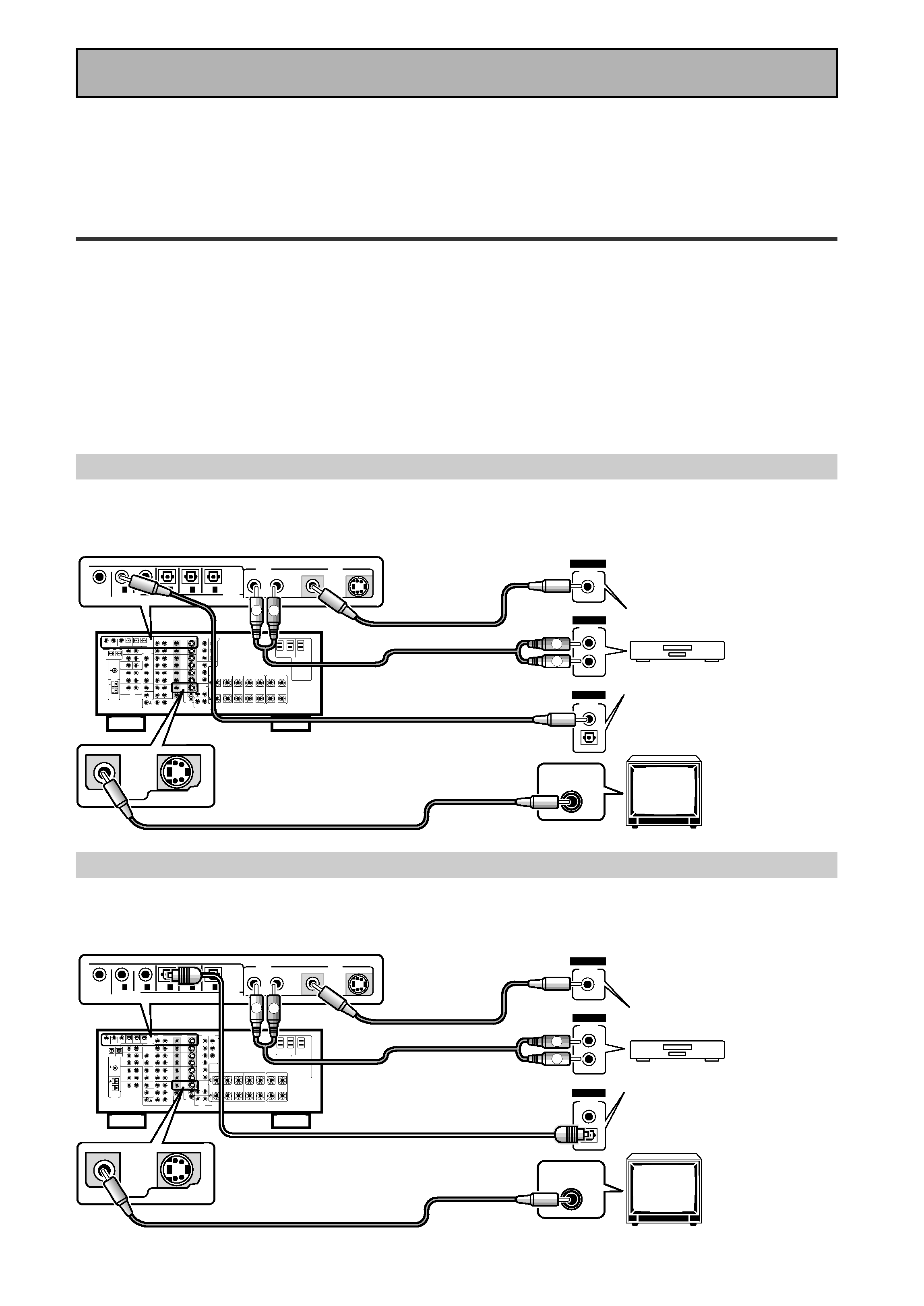
1 Hooking Up Your DVD Player & TV
In order to use Dolby Digital/DTS soundtracks which are at the heart of home theater you need to hook up your
DVD player with digital audio connections. You can do this by either a coaxial or an optical connection, you don't
need to do both. The quality of these two types of connections is the same but since some digital components
only have one type of digital terminal you need to figure out which yours has and hook it up to the appropriate
terminal on the receiver. In order to do this you will need the proper cable. For coaxial connections you can use a
regular RCA stereo cord or the specially-made coaxial cords, they have the same type of plugs. For optical
connections you will need a special optical cord which you can buy at your local stereo store. Also hook up the
video connection of your DVD player, the analog audio (for recording the audio on DVDs, use regular RCA stereo
cords), and your TV (it's easiest to use a regular composite RCA video cords) as shown below. It is important
that you hook up your TV (or monitor) in order to see a video image as well as the on screen displays (OSDs)
shown by this receiver (for more on p.16-17). We also recommend hooking up your all your digital components
to analog audio jacks. For this you can use regular RCA stereo cords.
Coaxial Digital Connection
If your DVD player has a coaxial terminal (not a PCM-only output) for the audio out hook it up using this terminal.
Follow the diagram below. This is the best scenario, as you will be able to follow the default settings of this
receiver and won't need to assign the digital inputs.
Optical Digital Connection
If your DVD player has an optical terminal (not a PCM-only output) for the audio out you can hook it up using this
following the diagram below. You will need to assign the digital input (tell the receiver which input you put your
DVD digital audio into). See page VI for this.
(not a PCM-only output)
(not a PCM-only output)
DVD player
OUTPUT
DIGITAL
STEREO
R
L
ANALOG
VIDEO
OUT
VIDEO
VIDEO INPUT
DVD /
LD
IN
S VIDEO
VIDEO
VIDEO
AUDIO
IN
IN 5
IN 4
IN 3
2 RF IN
(AC-3)
IN 2
IN 1
MONITOR
OUT1
PCM/
2/
DTS/
MPEG
DIGITAL
L
R
R
L
RCA video cord
RCA video cord
RCA stereo cord
coaxial cord
DVD player
OUTPUT
DIGITAL
STEREO
R
L
ANALOG
VIDEO
OUT
VIDEO
VIDEO INPUT
DVD /
LD
IN
S VIDEO
VIDEO
VIDEO
AUDIO
IN
IN 5
IN 4
IN 3
2 RF IN
(AC-3)
IN 2
IN 1
MONITOR
OUT1
L
R
R
L
RCA video cord
RCA video cord
RCA stereo cord
optical cord
PCM/
2/
DTS/
MPEG
DIGITAL
IV
En
Quick Start Guide
2
2
2
2
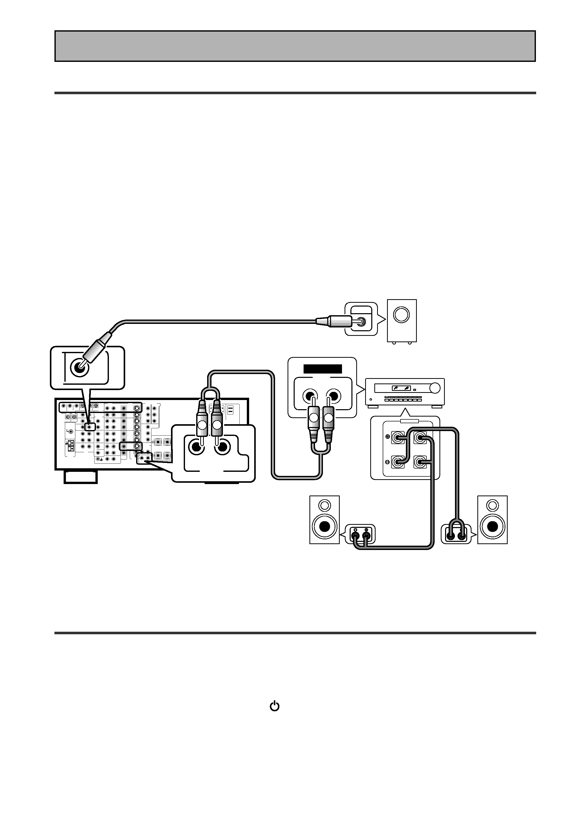
2 Speaker Connections
Home theater is designed to be setup with five, or seven speakers (front left & right; center; surround left &
right; and, optimally, surround back left & right) and a subwoofer but you can use this receiver with fewer
speakers. Hook up the speakers you have to the A speaker terminals on the back of the receiver. If you only
have two speakers hook them up as "FRONT". If you have three hook up the single speaker as "CENTER".
Follow the diagram on p.19 in order to hook up all your speakers. A center speaker is very important for
watching films because the dialog comes from the center speaker in digital soundtracks. If you do not have a
CENTER speaker you must tell the receiver the CENTER channel is OFF or when you listen to digital
soundtracks you won't hear any dialog. Use the instructions on page 33-34 in order to do this.
Follow the diagram below to hook up an additional amplifier in order to use surround back speakers. These
speakers are important to hear all the sound channels on new, eight channel home theater DVDs. The diagram
below also explains how to hook up a subwoofer which provides realistic bass sounds.
Make sure you connect the speaker on the right to the right terminal and the speaker on the left to the left
terminal. Also make sure the positive and negative (+/) terminals on the amplifier match those on the speakers.
3
3
3
3
3 Setting up the Remote Control & Unit
1 Put the batteries in the remote control.
2 Plug the main unit into a wall outlet.
3 Press
_ ON/ -- OFF button and the
STANDBY/ON button on the receiver to
put the receiver in ON mode.
R
L (Single)
SURROUND
BACK
PRE OUT
SUB
WOOFER
Surround back
speaker (Right)
Surround back
speaker (Left)
INPUT
Powered
subwoofer
Additional Amplifier (See p.21)
INPUT
L
L
R
R
ANALOG
FRONT
SPEAKERS
L
L
R
R
RCA stereo cord
RCA audio cord
V
En
Quick Start Guide
4
4
4
4
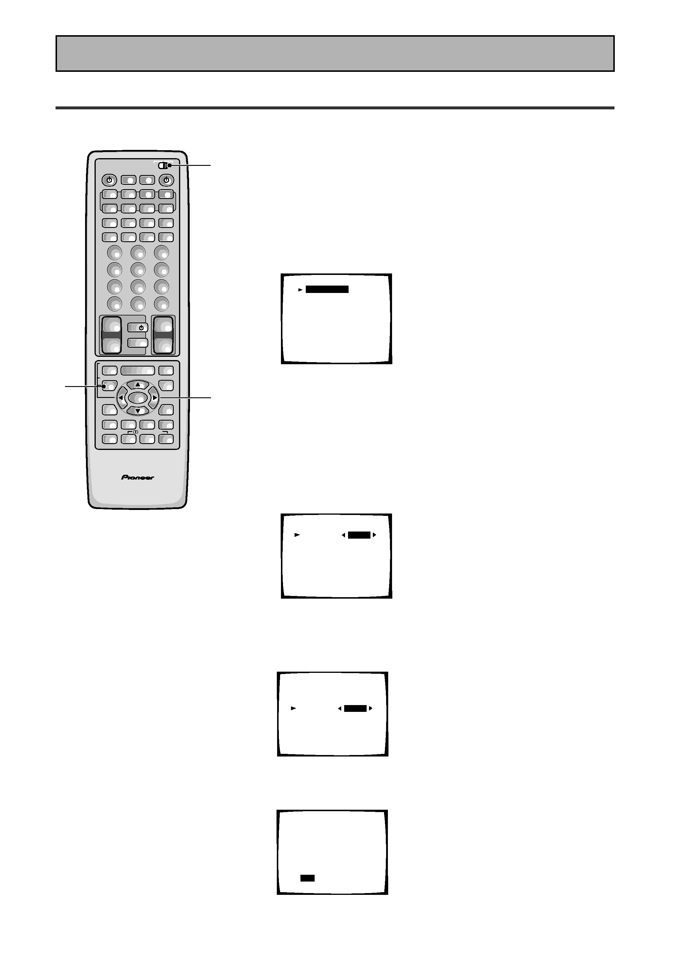
4 Digital Input Assignment
This is only necessary if you did not hook up your DVD to DIGITAL IN 1, as in the first diagram on p.III
1 Set the remote control slide switch to SETUP.
Also make sure your TV is on and set to the receiver.
· When you're done setting up the receiver, remember to set
the slide switch back to USE.
2 Press the SYSTEM SETUP button.
You should see the following display on your TV.
System Setup
[Digital-In Select]
[Speaker Setting]
[Channel Delay]
[Channel Level]
[Crossover Network]
[Bass Peak Level]
[D-Range Control]
[Multi Channel In]
· You can escape from this screen at any time by pressing the
SYSTEM SETUP button again. None of the settings you
made will be entered in this case.
· If don't enter any settings the receiver will revert back to its
previous state after three minutes.
3 Digital in Select should be selected (if it isn't use
the
5¥ buttons to select it). Press ENTER.
You should see the following display on your TV.
Digital-In Select
Digital-1
Digital-2
Digital-3
Digital-4
Digital-5
AC-3 RF
[EXIT] L
[DVD/LD]
[
CD
]
[
MD
]
[TV/SAT ]
[ VCR1 ]
[DVD/LD]
4 Choose the Digital-3 you hooked up your DVD
player to and assign "DVD/LD" to it.
Use the
2 or 3 buttons to choose the DVD/LD setting.
5 Select EXIT with
5¥ buttons and press ENTER
to return to the SYSTEM SETUP MENU.
AV PRE-PROGRAMMED AND LEARNING
REMOTE CONTROL UNIT
3-5
1
2
/DTS/MPEG
S0URCE
DVD/LD
TV/SAT
VCR1
VCR2
CD
TV VOL
TV FUNC
MENU
ENTER
STEREO/
DIRECT
DSP
THX
LIGHT
MUTE
TV
VOLUME
MD/
TAPE1
TUNER
TVCONT
RECEIVER
USE
SETUP
MULTI
OPERATION
CLASS
MPX
DIRECT ACCESS
CHANNEL
STATION
TUNING
DISPLAY
RF ATT
TV CONTROL
FUNCTION
REMOTE SETUP
SYSTEM SETUP
INPUT
ATT
ADVANCED
MIDNIGHT
MULTI CH
INPUT
STANDARD
DIGITAL
NR
EFFECT/
CH SEL
SIGNAL
SELECT
BAND
SYSTEM
OFF
12
3
45
6
78
9
0
DISC
Î
8
73
1¡
4
¢
+
-
+
-
+
-
MULTI CONTROL
++
+
+10
Digital-In Select
Digital-1
Digital-2
Digital-3
Digital-4
Digital-5
AC-3 RF
[EXIT] L
[DVD/LD]
[
CD
]
[DVD/LD]
[TV/SAT ]
[ VCR1 ]
[DVD/LD]
Digital-In Select
Digital-1
Digital-2
Digital-3
Digital-4
Digital-5
AC-3 RF
[EXIT] L
[ OFF ]
[
CD
]
[DVD/LD]
[TV/SAT ]
[ VCR1 ]
[DVD/LD]