
PDP-S27-LR
Operating Instructions
Mode d'emploi
Bedienungsanleitung
Istruzioni per l'uso
Gebruiksaanwijzing
Manual de instrucciones
Speaker System
Enceintes acoustiques
Lautsprechersystem
Sistema di diffusori
Luidsprekersysteem
Sistema de altavoces
2
English
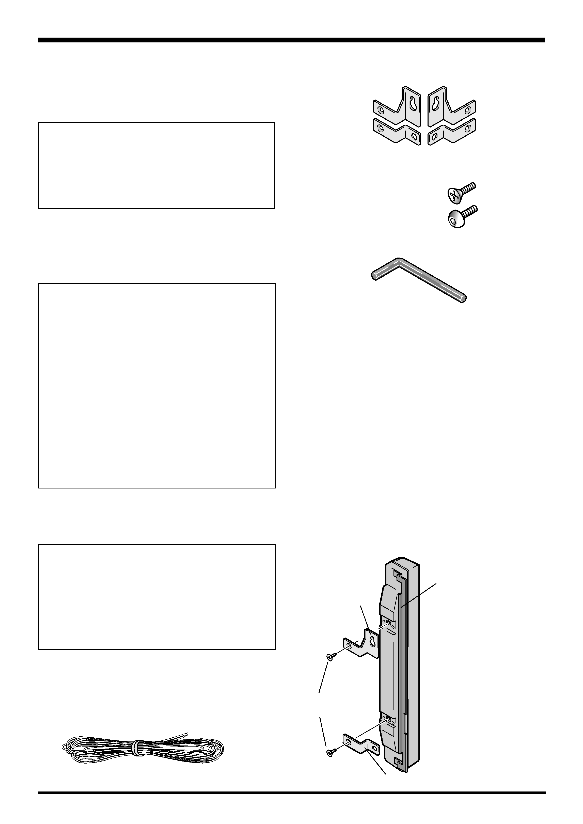
CHECKING THE ACCESSORIES
7 Speaker cable x 2
Thank you for buying this Pioneer product.
Please read through these operating instructions before
using your speaker system so you will know how to make
the most of its performance. After you have finished reading
the instructions, put them away in a safe place for future
reference.
BEFORE USE
÷ The nominal impedance of this speaker system is 8 ohms.
÷ In order to prevent damage to the speaker system
resulting from input overload, please observe the
following precautions:
÷ Do not supply power to the speaker system in
excess of the maximum permissable input. This
can result in damage or a possible fire hazard.
÷ When connecting or disconnecting pin-plugs, be
sure that amplifier power is OFF.
÷ When using a graphic equalizer to emphasize loud
sounds of a high frequency range, do not use
excessive amplifier volume.
÷ Do not force a low-powered amplifier to produce a
loud volume of sound (the amplifier's harmonic
distortion will be increased, and you may damage
the speaker).
÷ Please handle the speakers with sufficient care, as
the grille net and the cabinet can become damaged
or broken when they are subjected to strong external
impacts.
÷ Placing a CRT computer screen or CRT monitor near to
the speakers may result in interference or color distortion.
If this happens, distance the monitor from the speakers.
7 Operating Instructions
Flat countersunk head screw x 4
Hexagon socket head screw x 4
7 Speaker mounting fittings
For top right side x 1
For top left side x 1
For bottom x 2
7 Speaker mounting bolts
7 Mounting tool (Hex wrench)
NOTE:
÷ Always use the accessory mounting fittings for
installation.
÷ When screws other than those enclosed as accessories
are used to install the speakers, the speakers may drop
off or accidents may be caused. Always use the screws
enclosed as accessories.
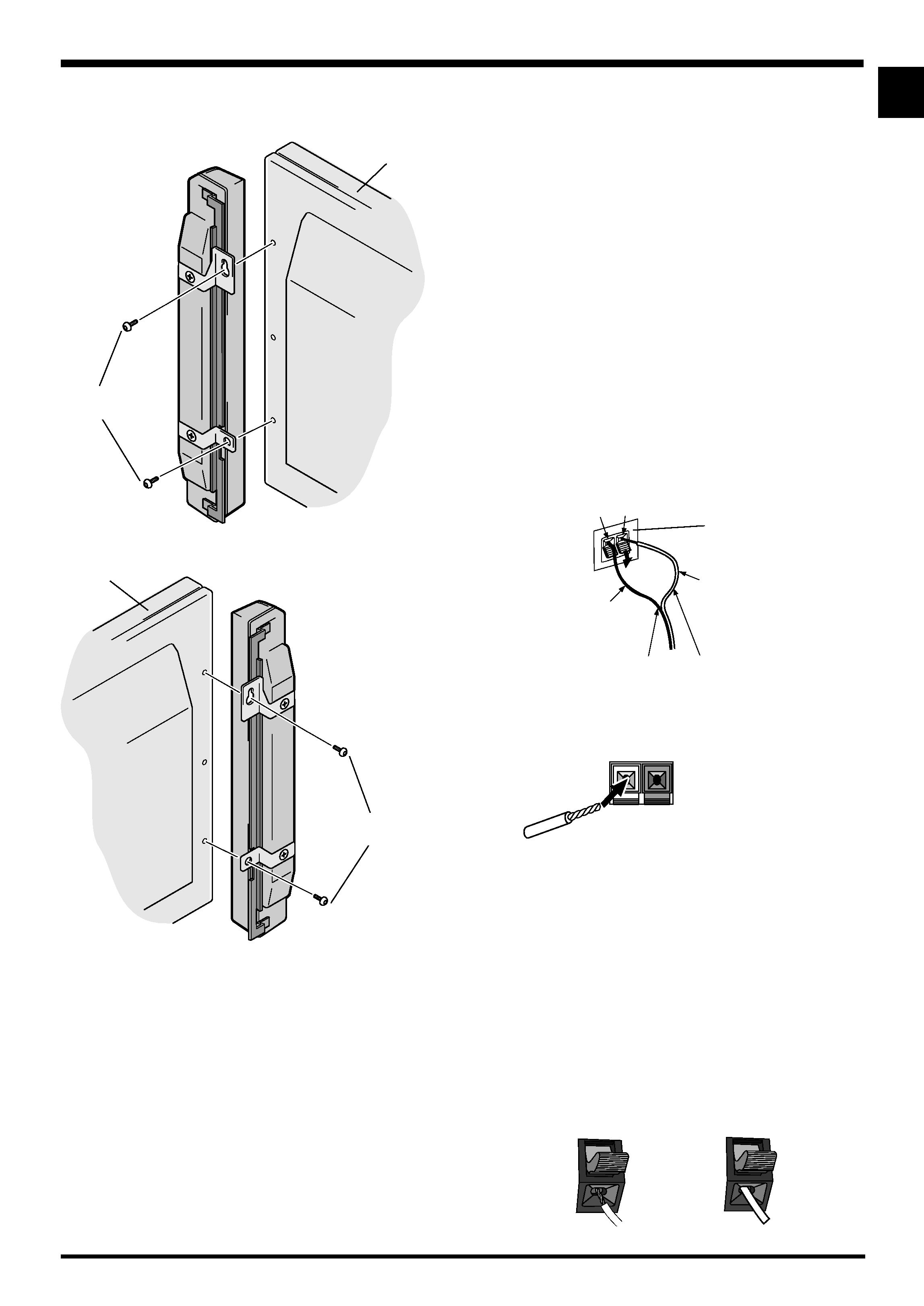
INSTALLATION ON THE PLASMA
DISPLAY
Perform installation according to the following steps 1 to 2.
1 Attach the mounting fittings to the
speakers.
The illustration shows the right speaker.
For top side
Mounting plate
Flat countersunk
head screw
For bottom
1 The top side fittings are dif-
ferent for the right and the
left side, and they must be
matched correctly.
2 Install the mounting fittings
with bolts at the positions
shown in the figure on the
left.
Notes on Installation Work:
This product is marketed assuming that it is installed by
qualified personnel with enough skill and competence.
Always have an installation specialist or your dealer install
and set up the product.
PIONEER cannot assume liabilities for damage caused
by mistake in installation or mounting, misuse,
modification or a natural disaster.
WARNING: Handling the cord on this product or
cords associated with accessories sold with the
product will expose you to lead, a chemical known to
the State of California and other governmental
entities to cause cancer and birth defects or other
reproductive harm.
D36-P4_En
Wash hands after handling
3
English
English
NOTE:
÷ When the display is to be moved after speaker
installation, do not hold the display by the speakers. Hold
the bottom of the display to move it.
÷ The grille nets are designed to protect the speakers,
however excessive force (such as pushing on, or insert-
ing objects between the grille nets) may result in dam-
age.
2 Attach the speakers to the display.
Install the unit marked "RIGHT" on the right side of the display.
Hexagon socket
head screw
Plasma display
Install the unit marked "LEFT" on the left side of the display.
Hexagon socket
head screw
1 To attach the speakers to the display, start by placing the
upper screw where indicated, tightening until there is a
small space of about 5mm between the head of the screw
and the display.
2 Check the rear of the speakers for the LEFT and RIGHT
indicators to make sure you are attaching the correct
speaker to the corresponding right or left side. Make sure
the UP mark is pointing up, and then attach the speaker
by fitting the upper mounting over the head of the screw
and sliding down until snug.
3 Affix the lower fitting to the display and tighten the screw
about halfway.
4 Adjust the position so that the gap between the speaker
and the display is uniform, and then tighten the screws
firmly.
Plasma display
CONNECTION TO A PLASMA
DISPLAY
1 Connecting the speaker cables
Before connecting the speaker cords, unplug the plasma
display from the power outlet. After you have finished
connecting up, plug the unit back into the power outlet.
1 Connect the input terminals of the speaker system and
the speaker output terminals of the plasma display with
the accessory speaker cable. Make sure the positive (
ª)
and negative (
·) terminals match when connecting.
1. Push the lever, insert the cable into the hole, and release
the lever.
2. For the output terminals on the plasma display, push the
lever, insert the cable into the hole, and release the lever.
÷ After connection to the terminals, pull lightly on the cable
to confirm that the tips of the cable are properly con-
nected to the terminals. An imperfect connection can
cause sound interruptions and noise.
÷ When cable cores stick out and ª and · lines are short-
circuited, an excessive load will be applied to the plasma
display and the operation will stop or trouble will be
caused.
÷ When the polarity is reversed for one speaker (left or right)
at the time of connection to the plasma display, the bass
reproduction will be reduced, the sound positioning will
be lost, and a correct stereo effect will not be obtained.
÷ If you insert the speaker cord too far so that the insulation
is touching the speaker terminal, you may not get any
sound.
< right >
< wrong >
White
To the
· terminal
To the
ª terminal
(Speaker input terminals of the speaker system)
· terminal (black) ª terminal (red)
Input terminal of speaker
White with gray line
ª·
R
Output terminal of plasma
display
4
English
2 How to route cables
Speed clamps and bead bands are included with the plasma
display for tidying your cables and keeping extra cable
length out of the way.
NOTE:
Cables can be routed to the right or left.
1 Organize cables together using the
speed clamps provided with the
plasma display.
Insert 1 into an appropriate hole on the rear of the unit, then
snap 2 into the back of 1 to fix the clamp.
Speed clamps are designed to be difficult to undo once in
place. Please attach carefully.
To remove speed clamps
Using pliers, twist the clamp 90° and pull it outward.
In some cases the clamp may have deteriorated over time
and may be damaged when removed.
1
2
To the right
*As viewed from the rear of the display.
Speed clamps
Speaker cable
To the left
System cable
To attach the speed clamps to the main unit
Connect the speed clamps using the 4 holes marked with ·
below, depending on the situation.
Speaker cable
Speed clamps
Speed clamps
Speaker cable
System cable
Speaker cable
Speed clamps

5
English
English
SPECIFICATIONS
NOTE:
Specifications and design subject to possible modification
without notice, due to improvements.
Cabinet : Enclosed type
Used speakers (two-way system) :
Woofer (for low tones) ............................ Oval cone type
Tweeter (for high tones) .................... 2.5 cm dome type
Nominal impedance ..................................................... 8
Frequency Range ..................................... 60 to 20,000 Hz
Sensitivity ................................ 82 dB/W (at 1 m distance)
Permissible input :
Max. input ............................................................... 12 W
Rated input .............................................................. 4 W
Crossover frequency ................................................ 3 kHz
External Dimensions ....... 74 (W) x 630 (H) x 101 (D) mm
Weight ..................................................................... 1.6 kg
Accessory parts (for 2 speakers)
.............................................................. Speaker cable x 2
............... Speaker mounting fittings (for top left side) x 1
............. Speaker mounting fittings (for top right side) x 1
....................... Speaker mounting fittings (for bottom) x 2
...................................... Flat countersunk head screw x 4
....................................... Hexagon socket head screw x 4
..................................... Mounting tool
(Hex wrench) x 1
................................................ Operating Instructions x 1
Published by Pioneer Corporation.
Copyright © 2004 Pioneer Corporation.
All rights reserved.
CABINET MAINTENANCE
÷ Use a polishing cloth or dry cloth to wipe off dust and
dirt.
÷ When the cabinet is very dirty, wipe with a soft cloth
moistened with water-diluted cleanser; then wipe again
with a dry cloth. Do not use furniture wax or cleaners.
They may damage the surface of the cabinet.
÷ Never use thinner, benzine, insecticide sprays and other
chemicals on or near the cabinets, since these will cor-
rode the surfaces.
÷ When a chemical cloth is used, read the cautions for the
chemical cloth carefully.