ORDER NO.
PIONEER CORPORATION 4-1, Meguro 1-chome, Meguro-ku, Tokyo 153-8654, Japan
PIONEER ELECTRONICS (USA) INC. P.O. Box 1760, Long Beach, CA 90801-1760, U.S.A.
PIONEER EUROPE NV Haven 1087, Keetberglaan 1, 9120 Melsele, Belgium
PIONEER ELECTRONICS ASIACENTRE PTE. LTD. 253 Alexandra Road, #04-01, Singapore 159936
PIONEER CORPORATION 2002
RRV2705
T ZZM OCT. 2002 Printed in Japan
PDP-S11
PDP-S11
XIN/E
SPEAKER SYSTEM
FOR PRECAUTION OF
REASSEMBLY AND DISASSEMBLY
65S
This service manual is intended for qualified service technicians; it is not meant for the
casual do-it-yourselfer. Qualified technicians have the necessary test equipment and
tools, and have been trained to properly and safely repair complex products such as
those covered by this manual.
Improperly performed repairs can adversely affect the safety and reliability
of the product and may void the warranty. If you are not qualified to perform the repair
of this product properly and safely, you should not risk trying to do so and refer the
repair to a qualified service technician.
WARNING
This product contains lead in solder and certain electrical parts contain chemicals
which are known to the state of California to cause cancer, birth defects or other
reproductive harm.
Health & Safety Code Section 25249.6 Proposition 65
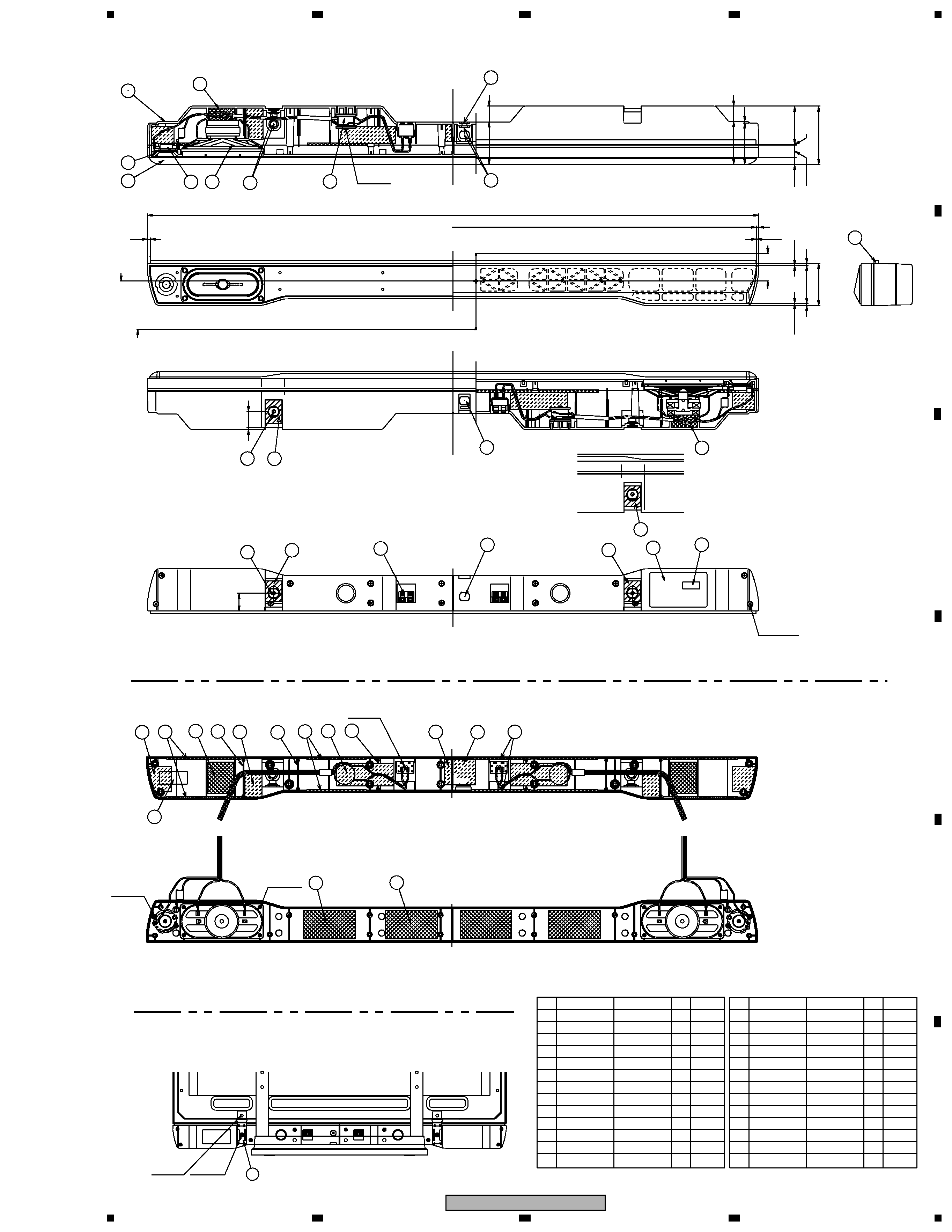
The speaker grille is attached to the baffle using 12 catches.
When removing, use a sharp pointed object, such as a plastic
board , or eyeleteer. Insert the point between the grille and
baffle, and gently prize the grille off. Alternatively, you can
remove the cabinet and the woofer unit, then push the grille out
from the inside.
Damage to the grille during removal may be unavoidable, but
be careful not to break the catches off of the baffle.
The woofer units are attached to the baffle by four screws from
the inside of the speaker cabinet. To remove the woofer units,
remove the four screws. When reattaching, make sure the large
connectors (attached to the speaker wire) are facing outward.
The tweeters are attached to the baffle by two screws from the
inside of the speaker cabinet. To remove the tweeter, remove
the two screws. When reattaching, make sure the larger connec-
tors are both facing inward. Also, the cutout of left one should
be facing top left; the cutout of right one, bottom left.
Network ASSY is attached from the inside using screws and
adhesive. To take out, remove the screw.
2
1
23
4
12
3
4
C
D
F
A
B
E
PDP-S11
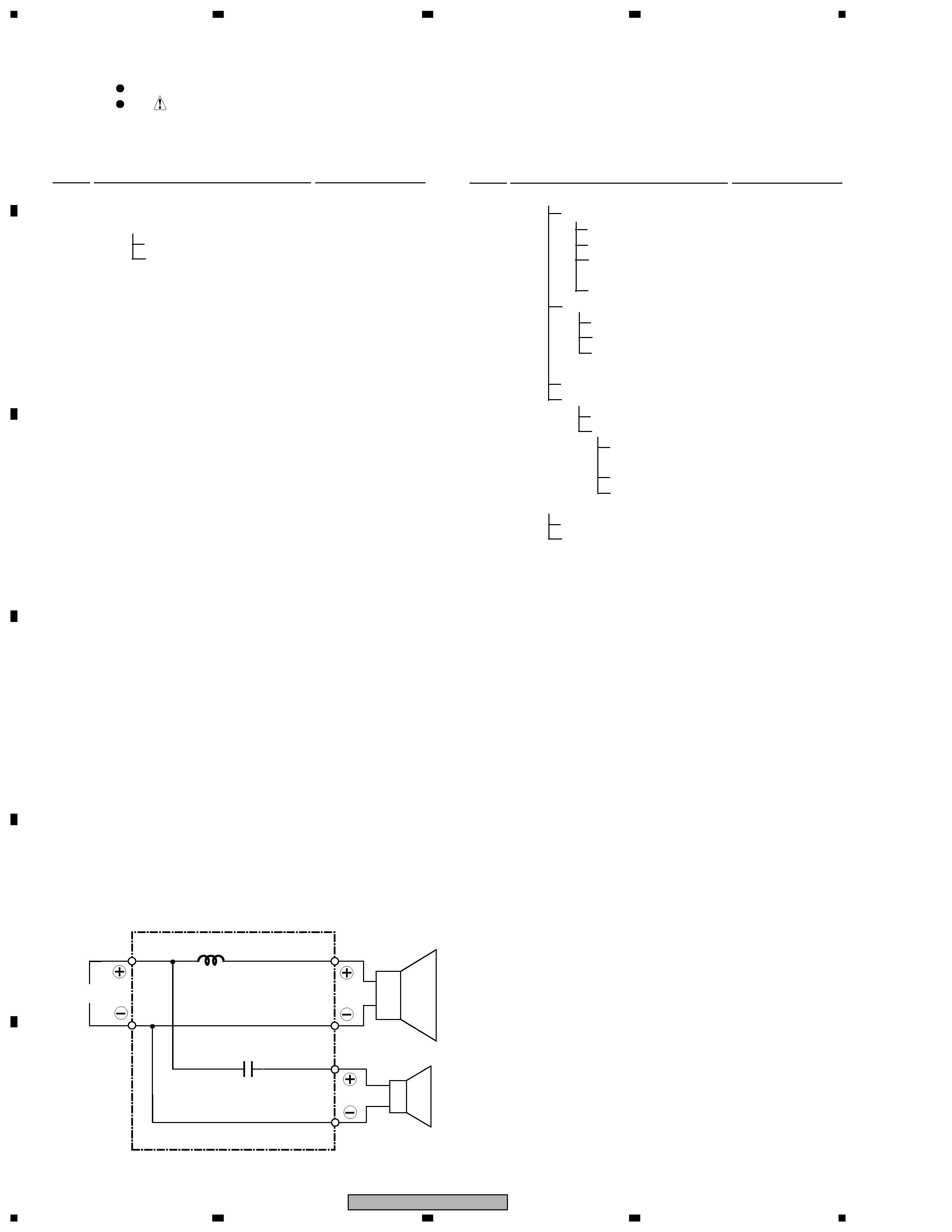
SCHEMATIC DIAGRAM
Parts marked by "NSP" are generally unavailable because they are not in our Master Spare Parts List.
The
mark found on some component parts indicates the importance of the safety factor of the part.
Therefore, when replacing, be sure to use parts of identical designation.
NOTES:
PARTS LIST
Mark No.
Description
Part No.
Mark No.
Description
Part No.
for PACKING
Woofer
I N
Red
Red
Black
Blue
White
White
Tweeter
1.8
µF/63V
1.0mH
NETWORT ASSY (KWN1041)
NSP
Cabinet
KNK1130
NSP
Baffle
KNK1131
Grille Assy
SMG1781
NSP
Grille Frame
KNK1132
NSP
Grille Cloth
SAS1545
Network Ass'y
KWN1041
NSP
Packing (
)
KEB1010
NSP
Packing (
)
KEB1013
Cushion (
)
KEC1096
Spacer (
)
KEP1122
Input Terminal
KKX1015
NSP
Acoustic Absorbent (
)
KMV1060
NSP
Acoustic Absorbent (
)
KMV1061
NSP
Acoustic Absorbent (
)
KMV1062
Metal Rinforce(B) (
)
KNA1145
Metal Rinforce(S) (
)
KNA1146
NSP
Model Label
SAN3194
Flanged Anchor Bolt
SBA1209
Serrated Flange Nut
SBN1052
Packing (
)
SEC1566
Packing (
)
SEC1673
Spacer (
)
SEP1254
Spacer (
)
SEP1255
65 Label
SRW1080
NSP
Label Serial
SRW1083
Speaker ( WF )
A142CU61-52F
Speaker (TW)
FK26AP02-69F
Screw (for TW )
APZ30P080FMC
Screw (for Input Terminal )
BBZ35P140FMC
Screw (for WF )
BPZ40P100FMC
Screw (for Cabinet - Baffle )
BPZ40P160FZK
Screw (for Network Coil )
BPZ40P350FMC
NSP
Accessory Set
SEA1599
NSP
Screws Set
KEA1197
Screw
CMZ50P120FZK
Bolt
SBA1210
Hexagon Lench
SEX1021
NSP
Polyethylene Bag S1
SHL1304
NSP
Speaker Wire Set
KEA1200
Speaker Wire
KDS1017
NSP
Polyethylene Bag S1
KHL1079
Wire Clamp
KNL1085
NSP
Polyethylene Bag S1
KHL1079
Bracket Assy Set
SEA1600
NSP
Polyethylene Bag S1
KHL1079
Bracket Assy
SNX1155
Cushion
KEC1095
Bracket
KNA1147
Spacer
SEP1256
NSP
Inst. Manual Set
SME3347
NSP
Polyethylene Bag S2
SHL1309
Instruction Manual
SRD1246
Side Pad(L)
KHA1291
Side Pad(R)
KHA1292
Top Pad
KHA1293
Bottom Pad
KHA1294
Protection Mat
KHC1397
Protection Mat
KHC1398
Packing Case
SHG2467
NSP
Label Serial
SRW1087
: Refer to " PRODUCT APPEARANCE ".
3
1
23
4
1
2
3
4
C
D
F
A
B
E
PDP-S11
PRODUCT APPEARANCE
25
25
26
10
9
12
11
14 - SCREW
25
27.5
24
9
15
26
8
(5)
(0.5)
1062
(0.5)
(0.5)
4
66
74
1070
7
15
5
4
3
2
1
26
26
6
1
2.5
72.5
12.5
21.5
67
27
75
102
2 x 1 - SCREW
28
74
4
31
4
4
SRW1083
1
4
KMV1062
SERIAL BARCODE LABEL
13
ACOUSTIC ABSORBENT
1
MODEL LABEL
SAN3194
4
SERRATED FLANGE NUT
SBN1052
2
KWN1041
NET WORK ASS'Y
12
11
10
9
2
IN-PUT TERMINAL
KKX1015
8
2
SPACER
KEP1122
7
6
2
SPEAKER
A142CU61-52F
5
2
TW
FK26AP02-69F
4
1
GRILLE ASS'Y
SMG1781
3
1
BAFFLE
KNK1131
2
1
CABINET
KNK1130
1
Remarks
Num.
Part Name
Part No.
No.
4
FLANGED ANCHOR BOLT
SBA1209
4
PACKING
SEC1673
26
25
1
65 LABEL
SRW1080
24
23
1
SPACER
SEP1254
22
SNX1155
BRACKET ASS'Y
2
3
4
2
PACKING
KEB1013
KEC1096
SPACER
KNA1146
SEC1566
ACOUSTIC ABSORBENT
PACKING
6
2
2
4
6
ACOUSTIC ABSORBENT
KEB1010
KMV1060
CUSHION
METAL RINFORCE(S)
SEP1255
CUSHION
4
KMV1061
21
20
19
18
17
16
KNA1145
14
METAL RINFORCE(B)
Remarks
Num.
Part Name
Part No.
No.
15
PDP-433HD ATTACHMENT
21
2 x 21 - SCREW
2 x 4 - SCREW
2 x 2 - SCREW
20
22
22
19
13
13
18
19
18
17
16
15
14
13
2 x 1 - BOLT
2 X 1 - SCREW
23