DJ MIXER
MESA DE MEZCLAS DJ
DJM-700-S
DJM-700-K
Operating Instructions
Manual de instrucciones
01_DJM-700_En.book 1
The exclamation point within an equilateral
triangle is intended to alert the user to the
presence of important operating and
maintenance (servicing) instructions in the
literature accompanying the appliance.
The lightning flash with arrowhead symbol,
within an equilateral triangle, is intended to
alert the user to the presence of uninsulated
"dangerous voltage" within the product's
enclosure that may be of sufficient
magnitude to constitute a risk of electric
shock to persons.
CAUTION:
TO PREVENT THE RISK OF ELECTRIC
SHOCK, DO NOT REMOVE COVER (OR
BACK). NO USER-SERVICEABLE PARTS
INSIDE. REFER SERVICING TO QUALIFIED
SERVICE PERSONNEL.
CAUTION
RISK OF ELECTRIC SHOCK
DO NOT OPEN
IMPORTANT
D3-4-2-1-1_En-A
Replacement and mounting of an AC plug on the power supply cord of this unit should be performed only by qualified
service personnel.
D3-4-2-1-2-2_B_En
IMPORTANT: THE MOULDED PLUG
This appliance is supplied with a moulded three pin mains plug for your safety and convenience. A 5 amp fuse is fitted in this plug. Should the
fuse need to be replaced, please ensure that the replacement fuse has a rating of 5 amps and that it is approved by ASTA or BSI to BS1362.
Check for the ASTA mark
or the BSI mark
on the body of the fuse.
If the plug contains a removable fuse cover, you must ensure that it is refitted when the fuse is replaced. If you lose the fuse cover the plug
must not be used until a replacement cover is obtained. A replacement fuse cover can be obtained from your local dealer.
If the fitted moulded plug is unsuitable for your socket outlet, then the fuse shall be removed and the plug cut off and disposed of
safely. There is a danger of severe electrical shock if the cut off plug is inserted into any 13 amp socket.
If a new plug is to be fitted, please observe the wiring code as shown below. If in any doubt, please consult a qualified electrician.
IMPORTANT: The wires in this mains lead are coloured in accordance with the following code:
Blue : Neutral
Brown : Live
As the colours of the wires in the mains lead of this appliance may not correspond with the coloured markings identifying the terminals in
your plug, proceed as follows ;
The wire which is coloured BLUE must be connected to the terminal which is marked with the
letter N or coloured BLACK.
The wire which is coloured BROWN must be connected to the terminal which is marked with the
letter L or coloured RED.
How to replace the fuse: Open the fuse compartment with a screwdriver and replace the fuse.
NOTE: This equipment has been tested and found to comply with the limits for a Class B digital device, pursuant to
Part 15 of the FCC Rules. These limits are designed to provide reasonable protection against harmful interference in
a residential installation. This equipment generates, uses, and can radiate radio frequency energy and, if not
installed and used in accordance with the instructions, may cause harmful interference to radio communications.
However, there is no guarantee that interference will not occur in a particular installation. If this equipment does
cause harmful interference to radio or television reception, which can be determined by turning the equipment off
and on, the user is encouraged to try to correct the interference by one or more of the following measures:
Reorient or relocate the receiving antenna.
Increase the separation between the equipment and receiver.
Connect the equipment into an outlet on a circuit different from that to which the receiver is connected.
Consult the dealer or an experienced radio/TV technician for help.
D8-10-1-2_En
CAUTION: This product satisfies FCC regulations when shielded cables and connectors are used to connect the
unit to other equipment. To prevent electromagnetic interference with electric appliances such as radios and
televisions, use shielded cables and connectors for connections.
D8-10-3a_En
Information to User
Alteration or modifications carried out without
appropriate authorization may invalidate the user's
right to operate the equipment.
D8-10-2_En
If the AC plug of this unit does not match the AC
outlet you want to use, the plug must be removed
and appropriate one fitted. Replacement and
mounting of an AC plug on the power supply cord of
this unit should be performed only by qualified
service personnel. If connected to an AC outlet, the
cut-off plug can cause severe electrical shock. Make
sure it is properly disposed of after removal.
The equipment should be disconnected by removing
the mains plug from the wall socket when left
unused for a long period of time (for example, when
on vacation).
D3-4-2-2-1a_A_En
CAUTION
The POWER switch on this unit will not completely
shut off all power from the AC outlet. Since the
power cord serves as the main disconnect device for
the unit, you will need to unplug it from the AC outlet
to shut down all power. Therefore, make sure the
unit has been installed so that the power cord can
be easily unplugged from the AC outlet in case of an
accident. To avoid fire hazard, the power cord should
also be unplugged from the AC outlet when left
unused for a long period of time (for example, when
on vacation).
D3-4-2-2-2a_A_En
WARNING
This equipment is not waterproof. To prevent a fire
or shock hazard, do not place any container filed
with liquid near this equipment (such as a vase or
flower pot) or expose it to dripping, splashing, rain
or moisture.
D3-4-2-1-3_A_En
WARNING
To prevent a fire hazard, do not place any naked
flame sources (such as a lighted candle) on the
equipment.
D3-4-2-1-7a_A_En
VENTILATION CAUTION
When installing this unit, make sure to leave space
around the unit for ventilation to improve heat
radiation (at least 5 cm at rear, and 3 cm at each
side).
WARNING
Slots and openings in the cabinet are provided for
ventilation to ensure reliable operation of the
product, and to protect it from overheating. To
prevent fire hazard, the openings should never be
blocked or covered with items (such as newspapers,
table-cloths, curtains) or by operating the
equipment on thick carpet or a bed.
D3-4-2-1-7b_A_En
Operating Environment
Operating environment temperature and humidity:
+5 ºC +35 ºC (+41 ºF +95 ºF); less than 85 %RH
(cooling vents not blocked)
Do not install this unit in a poorly ventilated area, or in
locations exposed to high humidity or direct sunlight (or
strong artificial light)
D3-4-2-1-7c_A_En
WARNING
The voltage of the available power supply differs
according to country or region. Be sure that the
power supply voltage of the area where this unit
will be used meets the required voltage (e.g., 230V
or 120V) written on the bottom panel. D3-4-2-1-4_A_En mod
Before plugging in for the first time, read the following
section carefully.
POWER-CORD CAUTION
Handle the power cord by the plug. Do not pull out the
plug by tugging the cord and never touch the power
cord when your hands are wet as this could cause a
short circuit or electric shock. Do not place the unit, a
piece of furniture, etc., on the power cord, or pinch the
cord. Never make a knot in the cord or tie it with other
cords. The power cords should be routed such that they
are not likely to be stepped on. A damaged power cord
can cause a fire or give you an electrical shock. Check
the power cord once in a while. When you find it
damaged, ask your nearest PIONEER authorized
service center or your dealer for a replacement.
S002_En
Thank you for buying this Pioneer product.
Please read through these operating instructions so you will know how to operate your model properly. After you have finished reading
the instructions, put them away in a safe place for future reference.
In some countries or regions, the shape of the power plug and power outlet may sometimes differ from that shown in the explanatory
drawings. However the method of connecting and operating the unit is the same.
K015 En
When using this product follow the instructions
written on the underside of the unit, which
concern rated voltage, etc.
D3-4-2-2-4_En
01_DJM-700_En.book 2

3
En
English
LINE VOLTAGE SELECTOR SWITCH
The line voltage selector switch is located on the side panel of this
mixier.The factory setting for the voltage selector is 220-240V.
Check that it is set properly before plugging the power cord into
the outlet. If the voltage is not properly set or if you move to an area
where the voltage requirements differ, adjust the selector switch
as follows:
· Use a medium-sized (flat blade) screwdriver. Insert the tip of the
screwdriver into the groove of the selector switch and set it so
that the power voltage marking of your area points to the arrow.
· For Taiwan, please set to 110-120V before using.
Contents
CONFIRM ACCESSORIES..............................................4
CAUTIONS REGARDING HANDLING............................4
Location .......................................................................................... 4
Cleaning the Unit........................................................................... 4
FEATURES ....................................................................4
CONNECTIONS .............................................................5
CONNECTION PANEL ................................................................... 5
CONNECTING INPUTS .................................................................. 6
CONNECTING EXTERNAL EFFECTORS, OUTPUT
CONNECTORS ............................................................................... 7
ABOUT MIDI CONNECTORS ........................................................ 8
CONNECTING MICROPHONE AND HEADPHONES ................. 8
CONNECTING THE POWER CORD.............................................. 8
NAMES AND FUNCTIONS OF PARTS ...........................9
MIXER OPERATIONS..................................................13
FADER START FUNCTION .......................................................... 14
EFFECT FUNCTIONS ...................................................16
PRODUCING BEAT EFFECTS...................................................... 18
MANUAL FILTER OPERATION.................................................... 19
EFFECT FREQUENCY FILTER OPERATION................................ 19
EFFECT PARAMETERS................................................................ 20
MIDI SETTINGS ..........................................................21
SYNCHRONIZING AUDIO SIGNALS TO EXTERNAL
SEQUENCER, OR USING DJM-700-S/DJM-700-K INFORMATION
TO OPERATE AN EXTERNAL SEQUENCER .............................. 21
MIDI MESSAGES ......................................................................... 22
PROGRAM CHANGE ................................................................... 24
SNAPSHOT................................................................................... 24
MIDI ON/OFF................................................................................ 24
TROUBLESHOOTING ..................................................25
SPECIFICATIONS ........................................................26
110-120V
220-240V
VOLTAGE
SELECTOR
01_DJM-700_En.book 3

4
En
CONFIRM
ACCESSORIES
Operating Instructions . . . . . . . . . . . . . . . . . . . . . . . . . . . . . . . . . . . . .1
CAUTIONS REGARDING
HANDLING
Location
Install the unit in a well-ventilated location where it will
not be exposed to high temperatures or humidity.
· Do not install the unit in a location which is exposed to direct
rays of the sun, or near stoves or radiators. Excessive heat
can adversely affect the cabinet and internal components.
Installation of the unit in a damp or dusty environment may
also result in a malfunction or accident. (Avoid installation
near cookers etc., where the unit may be exposed to oily
smoke, steam or heat.)
· When the unit is used inside a carrying case or DJ booth,
separate it from the walls or other equipment to improve
heat radiation.
Cleaning the Unit
· Use a polishing cloth to wipe off dust and dirt.
· When the surfaces are very dirty, wipe with a soft cloth
dipped in some neutral cleanser diluted five or six times with
water and wrung out well, then wipe again with a dry cloth.
Do not use furniture wax or cleaners.
· Never use thinners, benzene, insecticide sprays or other
chemicals on or near this unit, since these will corrode the
surfaces.
FEATURES
Designed for high sound quality
Analog signals are transmitted by the shortest circuitry and
converted to digital format at 96 kHz sampling rate via a 24-bit high
quality A/D converter. As a result, signals are passed to the digital
mixing stage in the best possible state. Mixing is performed with a
32-bit DSP, totally eliminating any loss in fidelity, while the ideal
level of filtering is introduced to produce optimum sound for DJ
play.
These features are housed in a high-rigidity chassis with high-
output power section and other features that carry on the high-
fidelity performance of the DJM-1000, thus ensuring the utmost in
clear and powerful club sound.
Manual Filter
This unit features Manual Effecter for more intuitive setting of
effects, thus expanding the potential range of DJ play. In addition,
by combining this with "beat effects," an even wider range of
effects can be produced, allowing a tremendous variety of remix
and DJ play.
Beat effects
The "beat effects" so popular on the DJM-600 are continued here.
Effects can be applied in linkage to the BPM (Beats Per Minute)
count, thus allowing the production of a variety of sounds.
Equipped with a broad range of special effects, including delay,
echo, trans, filter, flanger, phaser, reverb, robot, crush, roll, reverse
roll, uproll, and downroll.
This unit features an "effect frequency filter" allowing the user to
limit what frequency bands are subjected to effects, and which are
not. This enhances the degree of audio expression compared to
conventional effecters that are applied to the entire frequency
range.
Digital OUT
The digital output connectors support sampling rates 96 kHz/24-
bit format and 48 kHz/24-bit format, making the unit even more
convenient for cutting studio tracks or on other occasions when
high sound fidelity is required. (Only linear PCM is supported.)
MIDI OUT
Virtually all the dial and switch information of the DJM-700-S/
DJM-700-K can be output in MIDI signal format, allowing a
component supporting MIDI control to be controlled via MIDI.
Other functions
·A control cable can be used to connect the unit to a Pioneer DJ
CD player, thus allowing playback to be linked to operation of the
fader ("fader start play").
· Built-in "3-band equalizer" supports level control within the
range of +6 dB to 26 dB in each bandwidth.
· "Cross fader assignment" function allows each channel's input
to be assigned flexibly to a cross fader.
· "Talk over" function automatically lowers track volume during
microphone input.
· "Fader curve adjustment" function allows modification of the
cross fader and channel fader curves.
01_DJM-700_En.book 4
CONNECTIONS
5
En
English
CONNECTIONS
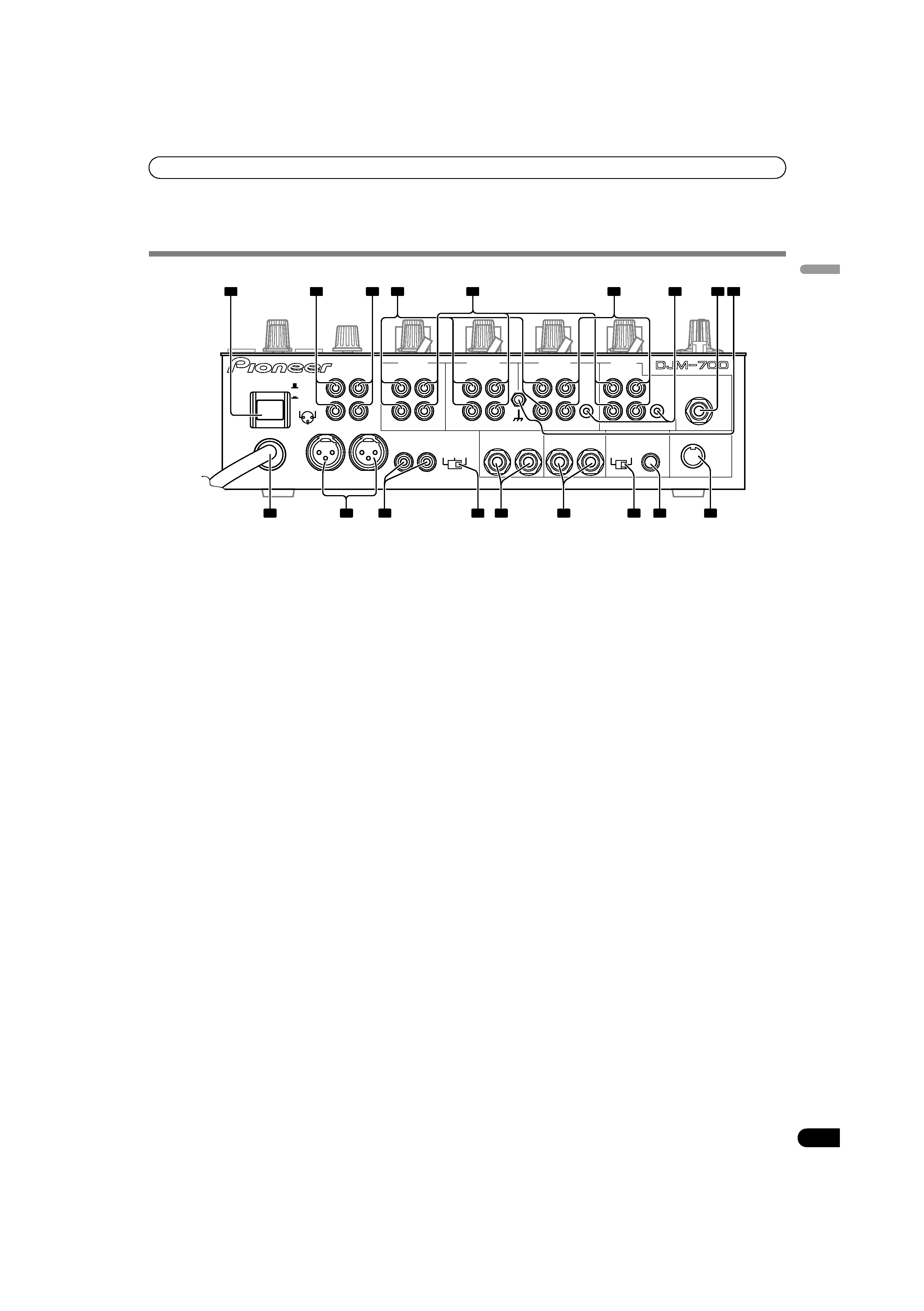
CONNECTION PANEL
1
POWER switch
2
BOOTH monitor output connectors
RCA-type booth monitor output jack.
The sound level from these connectors is controlled independently
by the
BOOTH MONITOR LEVEL dial, regardless of the position of
the
MASTER LEVEL dial.
3
Recording output connectors (REC)
RCA type output connectors for recording.
4
PHONO input connectors
RCA type phono level (MM cartridge) input connectors.
Do not use for inputting line level signals.
5
LINE input connectors
RCA type line level input connectors.
Use to connect a cassette deck or other line level output
component.
6CD input connectors
RCA type line level input connectors.
Use to connect a DJ CD player or other line level output
component.
7
CONTROL connectors
Ø3.5 mm mini-connector. Use to connect to the control connector
of a Pioneer DJ CD player.
When the connectors are connected, the DJM-700-S/DJM-700-K's
fader can be used to perform start/stop on the DJ CD player.
8
Two microphone input jacks (MIC 2)
Connect microphones equipped with phone-type plugs.
9
Signal grounding terminals (SIGNAL GND)
Reduces noise when connecting an analog turntable.
10 MIDI OUT connector
DIN type output connector.
Use to connect to other MIDI component (see P. 21).
11 DIGITAL OUT connector
RCA type digital coaxial output connector.
Master audio digital output.
12 Sampling frequency selector switch (fs 48 k/96 k)
Use to set the sampling frequency of the digital output to 96 kHz/
24-bit format or 48 kHz/24-bit format.
· Turn power off before changing this switch position.
13 RETURN connectors
Ø6.3 mm phone-type input connectors.
Use to connect to the output connectors of external effectors or
similar components.
When the L channel only is connected, the L channel input is
simultaneously input to the R channel.
14 SEND output connectors
Ø6.3 mm phone-type output connectors.
Use to connect to the input connectors of external effectors or
other similar components. When the L channel only is connected,
a L+R monaural signal is output.
15 Master output attenuator switch (MASTER ATT)
Use to attenuate the level of the master 1 and master 2 outputs.
Attenuation can be set to 0 dB, 3 dB, or 6 dB.
16 MASTER 2 output connectors
RCA type unbalanced output.
17 MASTER 1 output connectors
XLR type (male) balanced output.
· When using a cord with RCA-type plug, users are recommended
to connect the plug directly to the
MASTER 2 connectors
without using an XLR/RCA converter plug.
18 Power cord
Connect to ordinary AC outlet.
POWER
ON
OFF
BOOTH
REC
L
R
L
R
L
R
L
R
L
R
PHONO
LINE
CH-4
CH-3
CH-2
CH-1
PHONO
LINE
PHONO
SIGNAL GND
SEND
DIGITAL OUT
(MONO)
CD
RL
LINE
CONTROL
CONTROL
CD
1 GND
3 COLD
2 HOT
-6dB -3dB 0dB
MIC 2
RETURN
(MONO)
RL
RL
RL
MASTER1
MASTER2
MASTER
ATT.
48k
96k
fs(Hz)
MIDI OUT
1
2
3
4
7
8
9
10
11
12
15
17
18
13
16
14
5
6
01_DJM-700_En.book 5