ORDER NO.
PIONEER CORPORATION 4-1, Meguro 1-chome, Meguro-ku, Tokyo 153-8654, Japan
PIONEER ELECTRONICS (USA) INC. P.O. Box 1760, Long Beach, CA 90801-1760, U.S.A.
PIONEER EUROPE NV Haven 1087, Keetberglaan 1, 9120 Melsele, Belgium
PIONEER ELECTRONICS ASIACENTRE PTE. LTD. 253 Alexandra Road, #04-01, Singapore 159936
PIONEER CORPORATION 2007
DJM-700-S
RRV3644
DJ MIXER
DJM-700-S
DJM-700-K
THIS MANUAL IS APPLICABLE TO THE FOLLOWING MODEL(S) AND TYPE(S).
Model
Type
Power Requirement
Remarks
DJM-700-S
KUCXJ
AC 120 V
DJM-700-K
DJM-700-S
WYXJ5
AC 220 V to 240 V
DJM-700-K
DJM-700-S
RLXJ
AC 110 V to 120 V / AC 220 V to 240 V
DJM-700-K
For details, refer to "Important Check Points for good servicing".
T-ZZR SEPT. 2007 printed in Japan
DJM-700-S
2
12
34
1
234
C
D
F
A
B
E
SAFETY INFORMATION
1. SAFETY PRECAUTIONS
The following check should be performed for the
continued protection of the customer and service
technician.
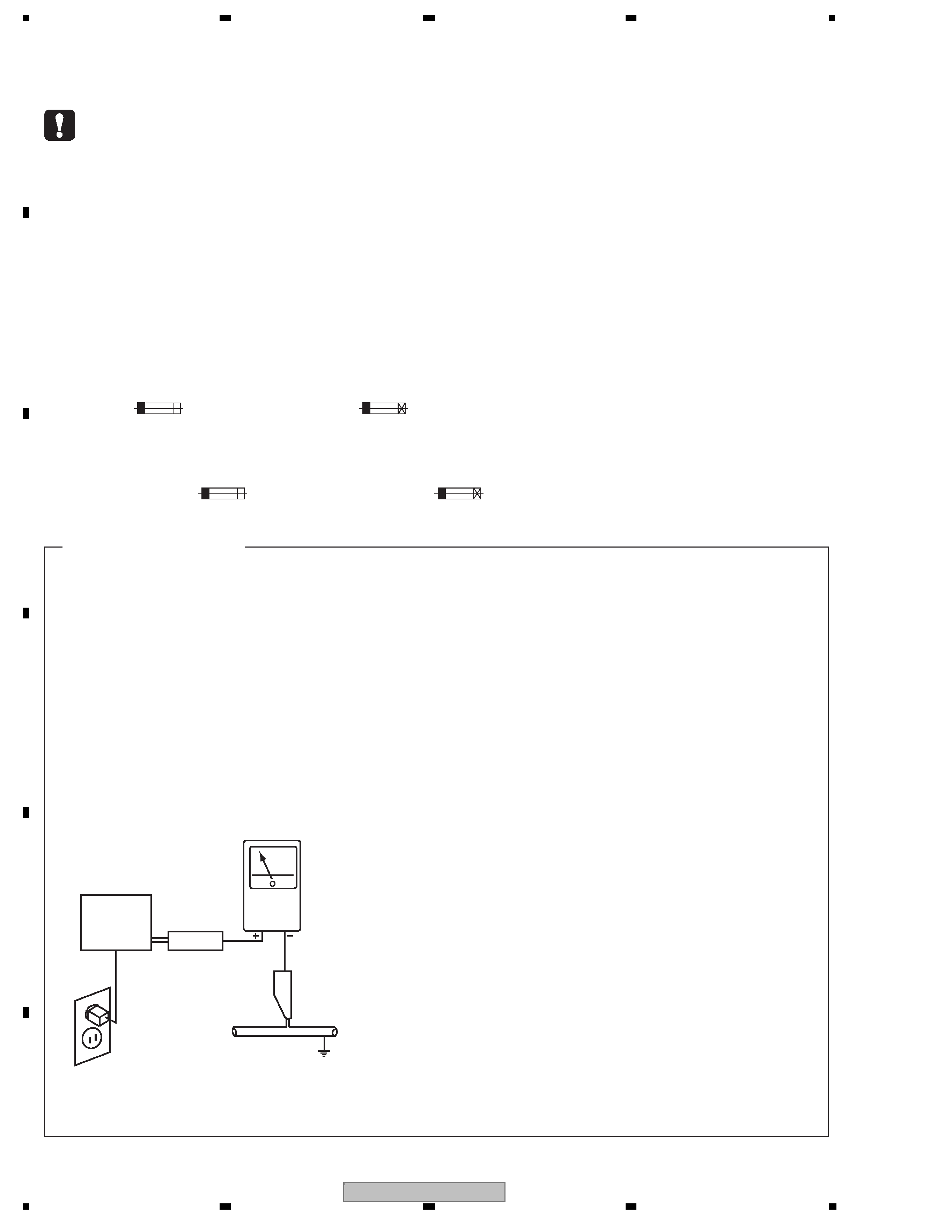
LEAKAGE CURRENT CHECK
Measure leakage current to a known earth ground
(water pipe, conduit, etc.) by connecting a leakage
current tester such as Simpson Model 229-2 or
equivalent between the earth ground and all exposed
metal parts of the appliance (input/output terminals,
screwheads, metal overlays, control shaft, etc.). Plug
the AC line cord of the appliance directly into a 120V
AC 60 Hz outlet and turn the AC power switch on. Any
current measured must not exceed 0.5 mA.
ANY
MEASUREMENTS
NOT WITHIN THE
LIMITS
OUTLINED ABOVE ARE INDICATIVE OF A POTENTIAL
SHOCK HAZARD AND MUST BE CORRECTED BEFORE
RETURNING THE APPLIANCE TO THE CUSTOMER.
2. PRODUCT SAFETY NOTICE
Many electrical and mechanical parts in the appliance
have special safety related characteristics. These are
often not evident from visual inspection nor the protection
afforded by them necessarily can be obtained by using
replacement components rated for voltage, wattage, etc.
Replacement parts which have these special safety
characteristics are identified in this Service Manual.
Electrical components having such features are
identified by marking with a
> on the schematics and on
the parts list in this Service Manual.
The use of a substitute replacement component which
does not have the same safety characteristics as the
PIONEER recommended replacement one, shown in the
parts list in this Service Manual, may create shock, fire,
or other hazards.
Product Safety is continuously under review and new
instructions are issued from time to time. For the latest
information, always consult the current PIONEER Service
Manual. A subscription to, or additional copies of,
PIONEER Service Manual may be obtained at a nominal
charge from PIONEER.
Leakage
current
tester
Reading should
not be above
0.5 mA
Device
under
test
Test all
exposed metal
surfaces
Also test with
plug reversed
(Using AC adapter
plug as required)
Earth
ground
AC Leakage Test
(FOR USA MODEL ONLY)
WARNING
This product contains lead in solder and certain electrical parts contain chemicals which are known to the state of California to
cause cancer, birth defects or other reproductive harm.
Health & Safety Code Section 25249.6 - Proposition 65
NOTICE
(FOR CANADIAN MODEL ONLY)
Fuse symbols
(fast operating fuse) and/or
(slow operating fuse) on PCB indicate that replacement parts must
be of identical designation.
REMARQUE
(POUR MODÈLE CANADIEN SEULEMENT)
Les symboles de fusible
(fusible de type rapide) et/ou
(fusible de type lent) sur CCI indiquent que les pièces
de remplacement doivent avoir la même désignation.
This service manual is intended for qualified service technicians ; it is not meant for the casual
do-it-yourselfer. Qualified technicians have the necessary test equipment and tools, and have been
trained to properly and safely repair complex products such as those covered by this manual.
Improperly performed repairs can adversely affect the safety and reliability of the product and may
void the warranty. If you are not qualified to perform the repair of this product properly and safely, you
should not risk trying to do so and refer the repair to a qualified service technician.
DJM-700-S
3
56
7
8
56
7
8
C
D
F
A
B
E
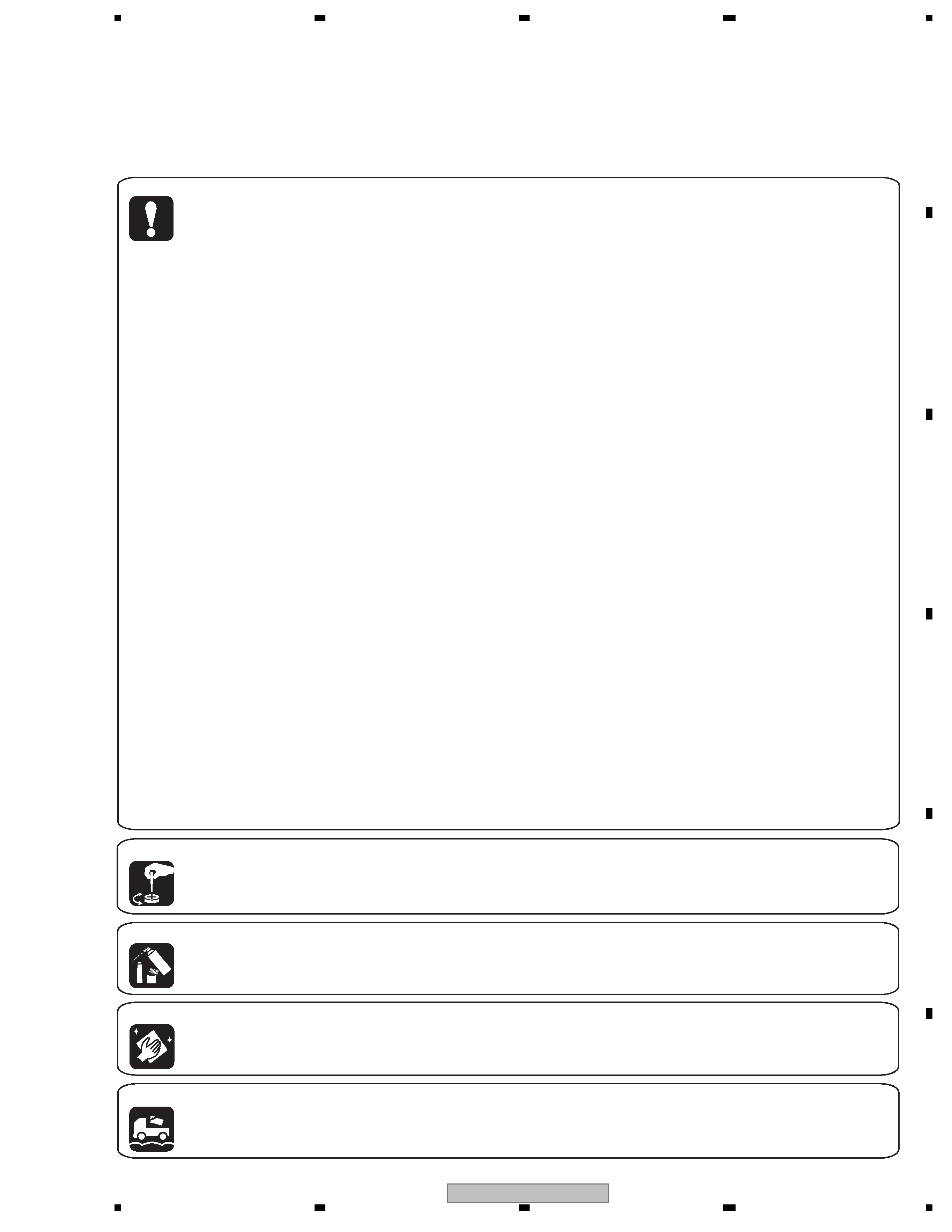
[Important Check Points for Good Servicing]
In this manual, procedures that must be performed during repairs are marked with the below symbol.
Please be sure to confirm and follow these procedures.
1. Product safety
Please conform to product regulations (such as safety and radiation regulations), and maintain a safe servicing environment by
following the safety instructions described in this manual.
1 Use specified parts for repair.
Use genuine parts. Be sure to use important parts for safety.
2 Do not perform modifications without proper instructions.
Please follow the specified safety methods when modification(addition/change of parts) is required due to interferences such as
radio/TV interference and foreign noise.
3 Make sure the soldering of repaired locations is properly performed.
When you solder while repairing, please be sure that there are no cold solder and other debris.
Soldering should be finished with the proper quantity. (Refer to the example)
4 Make sure the screws are tightly fastened.
Please be sure that all screws are fastened, and that there are no loose screws.
5 Make sure each connectors are correctly inserted.
Please be sure that all connectors are inserted, and that there are no imperfect insertion.
6 Make sure the wiring cables are set to their original state.
Please replace the wiring and cables to the original state after repairs.
In addition, be sure that there are no pinched wires, etc.
7 Make sure screws and soldering scraps do not remain inside the product.
Please check that neither solder debris nor screws remain inside the product.
8 There should be no semi-broken wires, scratches, melting, etc.on the coating of the power cord.
Damaged power cords may lead to fire accidents, so please be sure that there are no damages.
If you find a damaged power cord, please exchange it with a suitable one.
9 There should be no spark traces or similar marks on the power plug.
When spark traces or similar marks are found on the power supply plug, please check the connection and advise on secure
connections and suitable usage. Please exchange the power cord if necessary.
a Safe environment should be secured during servicing.
When you perform repairs, please pay attention to static electricity, furniture, household articles, etc. in order to prevent injuries.
Please pay attention to your surroundings and repair safely.
2. Adjustments
To keep the original performance of the products, optimum adjustments and confirmation of characteristics within specification.
Adjustments should be performed in accordance with the procedures/instructions described in this manual.
4. Cleaning
For parts that require cleaning, such as optical pickups, tape deck heads, lenses and mirrors used in projection monitors, proper
cleaning should be performed to restore their performances.
3. Lubricants, Glues, and Replacement parts
Use grease and adhesives that are equal to the specified substance.
Make sure the proper amount is applied.
5. Shipping mode and Shipping screws
To protect products from damages or failures during transit, the shipping mode should be set or the shipping screws should be
installed before shipment. Please be sure to follow this method especially if it is specified in this manual.

DJM-700-S
4
12
34
1
234
C
D
F
A
B
E
CONTENTS
SAFETY INFORMATION ..........................................................................................................................................................2
1. SERVICE PRECAUTIONS ....................................................................................................................................................5
1.1 NOTES ON SOLDERING ...............................................................................................................................................5
2. SPECIFICATIONS .................................................................................................................................................................6
2.1 ACCESSORIES ..............................................................................................................................................................6
2.2 SPECIFICATIONS...........................................................................................................................................................6
2.3 PANEL FACILITIES .........................................................................................................................................................7
3. BASIC ITEMS FOR SERVICE.............................................................................................................................................12
3.1 CHECK POINTS AFTER SERVICING..........................................................................................................................12
3.2 PCB LOCATIONS .........................................................................................................................................................13
3.3 JIGS LIST .....................................................................................................................................................................14
4. BLOCK DIAGRAM...............................................................................................................................................................16
4.1 OVERALL WIRING DIAGRAM......................................................................................................................................16
4.2 OVERALL BLOCK DIAGRAM.......................................................................................................................................18
4.3 MAIN BLOCK DIAGRAM ..............................................................................................................................................20
5. DIAGNOSIS.........................................................................................................................................................................22
5.1 TEST MODE .................................................................................................................................................................22
5.2 UPDATING OF THE FIRMWARE .................................................................................................................................29
5.3 HOW TO UPDATE.........................................................................................................................................................33
5.4 POWER ON SEQUENCE .............................................................................................................................................38
6. SERVICE MODE .................................................................................................................................................................41
7. DISASSEMBLY....................................................................................................................................................................42
8. EACH SETTING AND ADJUSTMENT ................................................................................................................................46
9. EXPLODED VIEWS AND PARTS LIST...............................................................................................................................48
9.1 PACKING SECTION .....................................................................................................................................................48
9.2 EXTERIOR SECTION...................................................................................................................................................50
9.3 CONTROL PANEL SECTION .......................................................................................................................................54
10. SCHEMATIC DIAGRAM ....................................................................................................................................................56
10.1 INPUT ASSY (1/6) ......................................................................................................................................................56
10.2 INPUT ASSY (2/6) ......................................................................................................................................................58
10.3 INPUT ASSY (3/6) ......................................................................................................................................................60
10.4 INPUT ASSY (4/6) ......................................................................................................................................................62
10.5 INPUT ASSY (5/6) ......................................................................................................................................................64
10.6 INPUT ASSY (6/6) ......................................................................................................................................................66
10.7 MIC1 JACK ASSY .......................................................................................................................................................68
10.8 MIC VR ASSY .............................................................................................................................................................69
10.9 MAIN ASSY (1/4) ........................................................................................................................................................70
10.10 MAIN ASSY (2/4) ......................................................................................................................................................72
10.11 MAIN ASSY (3/4) ......................................................................................................................................................74
10.12 MAIN ASSY (4/4) ......................................................................................................................................................76
10.13 PANEL 1 ASSY .........................................................................................................................................................78
10.14 PANEL 2 ASSY .........................................................................................................................................................80
10.15 OUTPUT ASSY (1/6) ................................................................................................................................................82
10.16 OUTPUT ASSY (2/6) ................................................................................................................................................84
10.17 OUTPUT ASSY (3/6) ................................................................................................................................................86
10.18 OUTPUT ASSY (4/6) ................................................................................................................................................88
10.19 OUTPUT ASSY (5/6) ................................................................................................................................................90
10.20 OUTPUT ASSY (6/6) ................................................................................................................................................92
10.21 FADER (CROSS), (CH1), (CH2), (CH3) and (CH4) ASSYS.....................................................................................94
10.22 HP JACK ASSY ........................................................................................................................................................95
10.23 REG ASSY................................................................................................................................................................96
10.24 TRANS ASSY ...........................................................................................................................................................97
10.25 PRIMARY ASSY .......................................................................................................................................................98
10.26 VOLTAGES..............................................................................................................................................................100
10.27 WAVEFORMS .........................................................................................................................................................105
11. PCB CONNECTION DIAGRAM ......................................................................................................................................110
11.1 INPUT, MIC1 JACK and MIC VR ASSYS..................................................................................................................110
11.2 MAIN ASSY ..............................................................................................................................................................114
11.3 PANEL 1 ASSY .........................................................................................................................................................118
11.4 PANEL 2, FADER (CROSS), (CH1), (CH2), (CH3) and (CH4) ASSYS ....................................................................122
11.5 OUTPUT and HP JACK ASSYS ...............................................................................................................................126
11.6 REG, TRANS and PRIMARY ASSYS .......................................................................................................................130
12. PCB PARTS LIST ............................................................................................................................................................134

DJM-700-S
5
56
7
8
56
7
8
C
D
F
A
B
E
1. SERVICE PRECAUTIONS
1.1 NOTES ON SOLDERING
· For environmental protection, lead-free solder is used on the printed circuit boards mounted in this unit.
Be sure to use lead-free solder and a soldering iron that can meet specifications for use with lead-free solders for repairs
accompanied by reworking of soldering.
· Compared with conventional eutectic solders, lead-free solders have higher melting points, by approximately 40
°C.
Therefore, for lead-free soldering, the tip temperature of a soldering iron must be set to around 373
°C in general, although
the temperature depends on the heat capacity of the PC board on which reworking is required and the weight of the tip of
the soldering iron.
Compared with eutectic solders, lead-free solders have higher bond strengths but slower wetting times and higher melting
temperatures (hard to melt/easy to harden).
The following lead-free solders are available as service parts:
· Parts numbers of lead-free solder:
GYP1006 1.0 in dia.
GYP1007 0.6 in dia.
GYP1008 0.3 in dia.