DJ MIXER
MESA DE MEZCLAS DJ
DJM-400
Operating Instructions
Manual de instrucciones
2
<DRB1406>
En
WARNING
This equipment is not waterproof. To prevent a fire
or shock hazard, do not place any container filed
with liquid near this equipment (such as a vase or
flower pot) or expose it to dripping, splashing, rain
or moisture.
D3-4-2-1-3_A_En
WARNING
The voltage of the available power supply differs
according to country or region. Be sure that the
power supply voltage of the area where this unit
will be used meets the required voltage (e.g., 230V
or 120V) written on the rear panel.
D3-4-2-1-4_A_En
Before plugging in for the first time, read the following
section carefully.
NOTE: This equipment has been tested and found to comply with the limits for a Class B digital device, pursuant to
Part 15 of the FCC Rules. These limits are designed to provide reasonable protection against harmful interference in
a residential installation. This equipment generates, uses, and can radiate radio frequency energy and, if not
installed and used in accordance with the instructions, may cause harmful interference to radio communications.
However, there is no guarantee that interference will not occur in a particular installation. If this equipment does
cause harmful interference to radio or television reception, which can be determined by turning the equipment off
and on, the user is encouraged to try to correct the interference by one or more of the following measures:
Reorient or relocate the receiving antenna.
Increase the separation between the equipment and receiver.
Connect the equipment into an outlet on a circuit different from that to which the receiver is connected.
Consult the dealer or an experienced radio/TV technician for help.
D8-10-1-2_En
CAUTION: This product satisfies FCC regulations when shielded cables and connectors are used to connect the
unit to other equipment. To prevent electromagnetic interference with electric appliances such as radios and
televisions, use shielded cables and connectors for connections.
D8-10-3a_En
The exclamation point within an equilateral
triangle is intended to alert the user to the
presence of important operating and
maintenance (servicing) instructions in the
literature accompanying the appliance.
The lightning flash with arrowhead symbol,
within an equilateral triangle, is intended to
alert the user to the presence of uninsulated
"dangerous voltage" within the product's
enclosure that may be of sufficient
magnitude to constitute a risk of electric
shock to persons.
CAUTION:
TO PREVENT THE RISK OF ELECTRIC
SHOCK, DO NOT REMOVE COVER (OR
BACK). NO USER-SERVICEABLE PARTS
INSIDE. REFER SERVICING TO QUALIFIED
SERVICE PERSONNEL.
CAUTION
RISK OF ELECTRIC SHOCK
DO NOT OPEN
IMPORTANT
D3-4-2-1-1_En-A
WARNING
To prevent a fire hazard, do not place any naked
flame sources (such as a lighted candle) on the
equipment.
D3-4-2-1-7a_A_En
VENTILATION CAUTION
When installing this unit, make sure to leave space
around the unit for ventilation to improve heat
radiation (at least 5 cm at rear, and 3 cm at each
side).
WARNING
Slots and openings in the cabinet are provided for
ventilation to ensure reliable operation of the
product, and to protect it from overheating. To
prevent fire hazard, the openings should never be
blocked or covered with items (such as newspapers,
table-cloths, curtains) or by operating the
equipment on thick carpet or a bed.
D3-4-2-1-7b_A_En
Operating Environment
Operating environment temperature and humidity:
+5 ºC +35 ºC (+41 ºF +95 ºF); less than 85 %RH
(cooling vents not blocked)
Do not install this unit in a poorly ventilated area, or in
locations exposed to high humidity or direct sunlight (or
strong artificial light)
D3-4-2-1-7c_A_En
If the AC plug of this unit does not match the AC
outlet you want to use, the plug must be removed
and appropriate one fitted. Replacement and
mounting of an AC plug on the power supply cord of
this unit should be performed only by qualified
service personnel. If connected to an AC outlet, the
cut-off plug can cause severe electrical shock. Make
sure it is properly disposed of after removal.
The equipment should be disconnected by removing
the mains plug from the wall socket when left
unused for a long period of time (for example, when
on vacation).
D3-4-2-2-1a_A_En
CAUTION
The POWER switch on this unit will not completely
shut off all power from the AC outlet. Since the
power cord serves as the main disconnect device for
the unit, you will need to unplug it from the AC outlet
to shut down all power. Therefore, make sure the
unit has been installed so that the power cord can
be easily unplugged from the AC outlet in case of an
accident. To avoid fire hazard, the power cord should
also be unplugged from the AC outlet when left
unused for a long period of time (for example, when
on vacation).
D3-4-2-2-2a_A_En
Information to User
Alteration or modifications carried out without
appropriate authorization may invalidate the user's
right to operate the equipment.
D8-10-2_En
POWER-CORD CAUTION
Handle the power cord by the plug. Do not pull out the
plug by tugging the cord and never touch the power
cord when your hands are wet as this could cause a
short circuit or electric shock. Do not place the unit, a
piece of furniture, etc., on the power cord, or pinch the
cord. Never make a knot in the cord or tie it with other
cords. The power cords should be routed such that they
are not likely to be stepped on. A damaged power cord
can cause a fire or give you an electrical shock. Check
the power cord once in a while. When you find it
damaged, ask your nearest PIONEER authorized
service center or your dealer for a replacement.
S002_En
Thank you for buying this Pioneer product.
Please read through these operating instructions so you will know how to operate your model properly. After you have finished reading
the instructions, put them away in a safe place for future reference.
In some countries or regions, the shape of the power plug and power outlet may sometimes differ from that shown in the explanatory
drawings. However the method of connecting and operating the unit is the same.
K015 En
Location
Install the unit in a well-ventilated location where it will not
be exposed to high temperatures or humidity.
÷ Do not install the unit in a location which is exposed to
direct rays of the sun, or near stoves or radiators. Excessive
heat can adversely affect the cabinet and internal
components. Installation of the unit in a damp or dusty
environment may also result in a malfunction or accident.
(Avoid installation near cookers etc., where the unit may be
exposed to oily smoke, steam or heat.)
CAUTIONS REGARDING HANDLING
÷ When the unit is used inside a carrying case or DJ booth,
separate it from the walls or other equipment to improve
heat radiation.
Cleaning the Unit
÷ Use a polishing cloth to wipe off dust and dirt.
÷ When the surfaces are very dirty, wipe with a soft cloth
dipped in some neutral cleanser diluted five or six times
with water and wrung out well, then wipe again with a dry
cloth. Do not use furniture wax or cleaners.
÷ Never use thinners, benzene, insecticide sprays or other
chemicals on or near this unit, since these will corrode the
surfaces.
Voltage selector
You can find the voltage selector switch on the right side of the
unit.
The factory setting for the voltage selector is 220 240 V.
Please set it to the correct voltage for your country or re-
gion.
· For Taiwan, please set to 110 120 V before using.
Before changing the voltage, disconnect the AC power cord.
Use a medium size screwdriver to change the voltage selector
switch.
D3-4-2-1-5_En
VOLTAGE
SELECTOR
110-120V 220-240V

English
3
<DRB1406>
En
CONTENTS
CAUTIONS REGARDING HANDLING ........................ 2
SPECIFICATIONS ......................................................... 3
FEATURES ................................................................... 3
BEFORE USING
CONNECTIONS ............................................................ 4
CONNECTION PANEL ........................................... 4
CONNECTING INPUTS .......................................... 5
CONNECTING OUTPUTS ...................................... 5
CONNECTING THE POWER CORD ...................... 5
NAMES AND FUNCTIONS OF PARTS ...................... 6
OPERATIONS
MIXER OPERATIONS .................................................. 8
BASIC OPERATIONS ............................................. 8
FADER START FUNCTION .................................... 9
EFFECT FUNCTIONS ................................................. 10
TYPES OF BEAT EFFECTS .................................. 10
PRODUCING BEAT EFFECTS .............................. 11
IN-LOOP SAMPLER ............................................. 11
EFFECT PARAMETERS ........................................ 12
OTHER
TROUBLESHOOTING ................................................ 13
BLOCK DIAGRAM ...................................................... 40
1 Designed for high sound quality
Analog signals are sampled at 96 kHz/24-bit, comparable to
professional performance levels. Mixing is performed with the same
type of 32-bit DSP as used in the DJM-1000 and DJM-800, thus
eliminating any loss in fidelity, and producing clear and powerful
club sound optimally suited for DJ play.
2 3-band equalizer with kill function
Equalizer functions are provided for each of the three bandwidths HI,
MID, and LOW, and a kill function is provided to drop the attenuation
level to
.
3 Wide variety of effects
1) Beat effects
The "beat effects" so popular on the DJM-600 have been given
further evolution. Effects can be applied in linkage to the BPM (Beats
Per Minute) count, thus allowing the production of a variety of
sounds. Some of the effects include delay, echo, filter, flanger,
phaser, robot, and roll.
2) Beat select buttons
Automatically set the effect time linked to the BPM. Allows selection
of desired BPM for synchronizing beat effects.
3) IN-LOOP sampler
Detects the current track's BPM and records up to 5 of 4-beat sources
in banks, and plays a loop in time with the track's BPM.
4 2 MIC input, AUX switching
Equipped with 2 MIC input jacks that can be switched to AUX,
allowing use as a third LINE input.
5 Auto talk-over
The auto talk-over function automatically reduces track volume when
microphone input is detected.
6 Other functions
¶ A control cable can be used to connect the unit to a Pioneer DJ CD
player, thus allowing playback to be linked to operation of the
fader ("fader start play").
¶ "Fader curve adjustment" function allows modification of the
cross fader curves.
¶ "Auto BPM counter" provides visual representation of a track's
tempo.
¶ Monitor auto assignment function can be used to assign channel
inputs and master outputs to the left and right channels of
monitor headphones.
¶ Full lineup of input/output systems. Provided with two each of CD
and LINE/PHONO (MM type) inputs and two microphone inputs
for a total of six input systems, together with two output systems.
FEATURES
SPECIFICATIONS
1.General
Power source ............. AC 110 V to 120 V/220 V to 240 V, 50 Hz/60 Hz
Power consumption ..................................................................... 13 W
Operating temperature ................................................. +5 °C to +35 °C
Operating humidity .................... 5 % to 85 % (without condensation)
Weight .......................................................................................... 3.2 kg
Maximum dimensions ................ 223 (W)
× 304.7 (D) × 106.6 (H) mm
2. Audio section
Sampling rate ............................................................................. 96 kHz
A/D, D/A converter ...................................................................... 24 bits
Frequency response
LINE ......................................................................... 20 Hz to 20 kHz
MIC .......................................................................... 20 Hz to 20 kHz
PHONO ......................................................... 20 Hz to 20 kHz (RIAA)
S/N ratio (at rated output)
LINE ......................................................................................... 97 dB
PHONO .................................................................................... 82 dB
MIC .......................................................................................... 78 dB
Distortion (LINE-MASTER OUT) ............................................... 0.007 %
Input level/ Impedance
PHONO ...................................................................... 52 dBu/47 k
MIC 1, MIC 2 ............................................................. 52 dBu/47 k
CD, LINE .................................................................... 12 dBu/47 k
Output Level/Impedance
MASTER OUT ............................................................ +2 dBu/10 k
PHONES ...................................................................... + 2 dBu/32
Crosstalk (LINE) ............................................................................ 78 dB
Channel equalizer response (Isolater)
HI ..................................................................... +9 dB to
(13 kHz)
MID .................................................................... +9 dB to
(1 kHz)
LOW ................................................................... +9 dB to
(70 Hz)
Microphone equalizer response
HI .............. 12 dB (full counterclockwise) to 0 dB (center) (10 kHz)
LOW ..................... 12 dB (full clockwise) to 0 dB (center) (100 Hz)
3. Input/output connector systems
PHONO/LINE input connectors
RCA pin jacks .................................................................................. 2
CD input connectors
RCA pin jacks .................................................................................. 2
MIC/AUX input connectors
Phone jacks (Ø6.3 mm) .................................................................. 2
MASTER output connectors
RCA pin jacks .................................................................................. 2
PHONES connectors
Stereo phone jack (Ø6.3 mm) ........................................................ 1
CONTROL connectors
Mini-phone jacks (Ø3.5 mm) .......................................................... 2
4. Accessories
Operating Instructions ......................................................................... 1
Power cord ........................................................................................... 1
Specifications and appearance are subject to change without notice.
4
<DRB1406>
En
CONNECTIONS
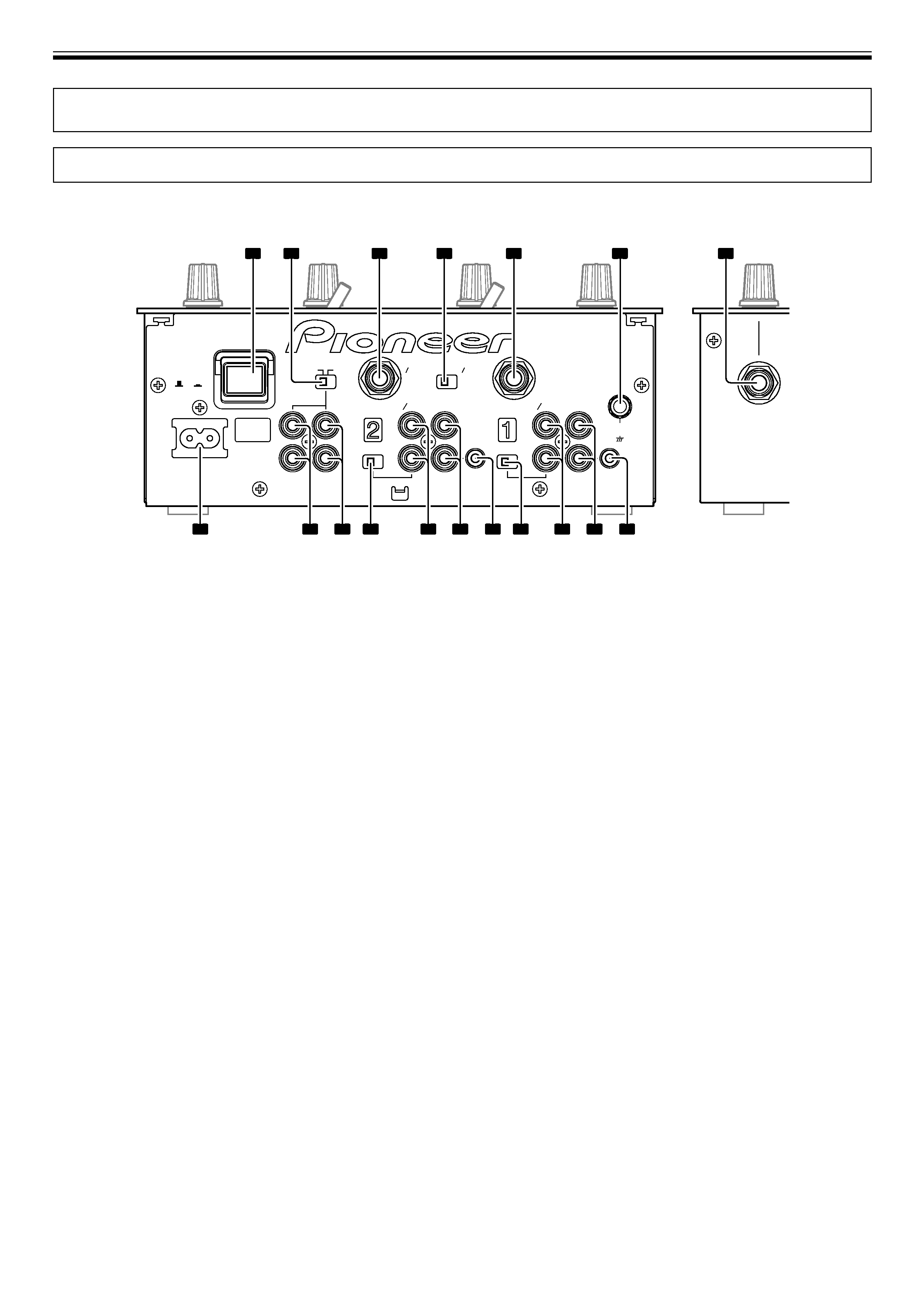
CONNECTION PANEL
CONNECTIONS
POWER
OFF
ON
AC IN
MASTER
OUT
MONO
STEREO
2
1
L
R
L
R
LINE PHONO
LINE
PHONO
MIC2
MIC1
AUX(R)
AUX(L)
AUX
MIC
CD
CONTROL
L
R
LINE PHONO
LINE
PHONO
CD
CONTROL
SIGNAL
GND
1
3
2
4
5
6
18
9
10
11
12
13
14
15
16
17
7
8
Rear panel
Front panel
1. POWER switch
2. STEREO/MONO selector switch
When switch is set to the [MONO] position, master output is in
monaural.
3. MIC2/AUX(R) input connector
Ø6.3 mm phone-type input connector. Use for microphone input, or
for right (R) channel of component with line level output.
4. MIC/AUX input selector switch
When this switch is set to [AUX], the MIC1 and MIC2 input connectors
function as AUX(L) and AUX(R) input connectors.
5. MIC1/AUX(L) input connector
Ø6.3 mm phone-type input connector. Use for microphone input, or
for left (L) channel of component with line level output.
6. Signal grounding terminal (SIGNAL GND)
Use to connect ground wires from analog players.
This is not a safety grounding terminal.
7. Channel 1 CONTROL connector
Ø3.5 mm mini-phone type connector. Connect to control connector
of the DJ CD player connected to channel 1 inputs.
When this connection is made, the DJ mixer's fader lever can be used
to perform fader start play and back cue on the channel 1 DJ CD
player.
8. Channel 1 CD input connectors (CD)
RCA type line level input connectors.
Use to connect a DJ CD player or other component with line level
output.
9. Channel 1 PHONO/LINE input connectors
RCA type phono level (for MM cartridge) or line level input
connectors.
Select function using channel 1 PHONO/LINE selector switch.
10. Channel 1 PHONO/LINE selector switch
Use to select function of channel 1 PHONO/LINE input connectors.
11. Channel 2 CONTROL connector
Ø3.5 mm mini-phone type connector. Connect to control connector
of the DJ CD player connected to channel 2 inputs.
When this connection is made, the DJ mixer's fader lever can be used
to perform fader start play and back cue on the channel 2 DJ CD
player.
12. Channel 2 CD input connectors (CD)
RCA type line level input connectors.
Use to connect a DJ CD player or other component with line level
output.
13. Channel 2 PHONO/LINE input connectors
RCA type phono level (for MM cartridge) or line level input
connectors.
Select function using channel 2 PHONO/LINE selector switch.
14. Channel 2 PHONO/LINE selector switch
Use to select function of channel 2 PHONO/LINE input connectors.
15. MASTER OUT 2 output connectors
RCA type unbalanced output.
16. MASTER OUT 1 output connectors
RCA type unbalanced output.
17. Power inlet (AC IN)
Use the accessory power cord to connect to an AC power outlet of the
proper voltage.
18. Headphones jack (PHONES)
Use to connect stereo headphones equipped with Ø6.3 mm stereo
headphones plug.
English
5
<DRB1406>
En
CONNECTIONS
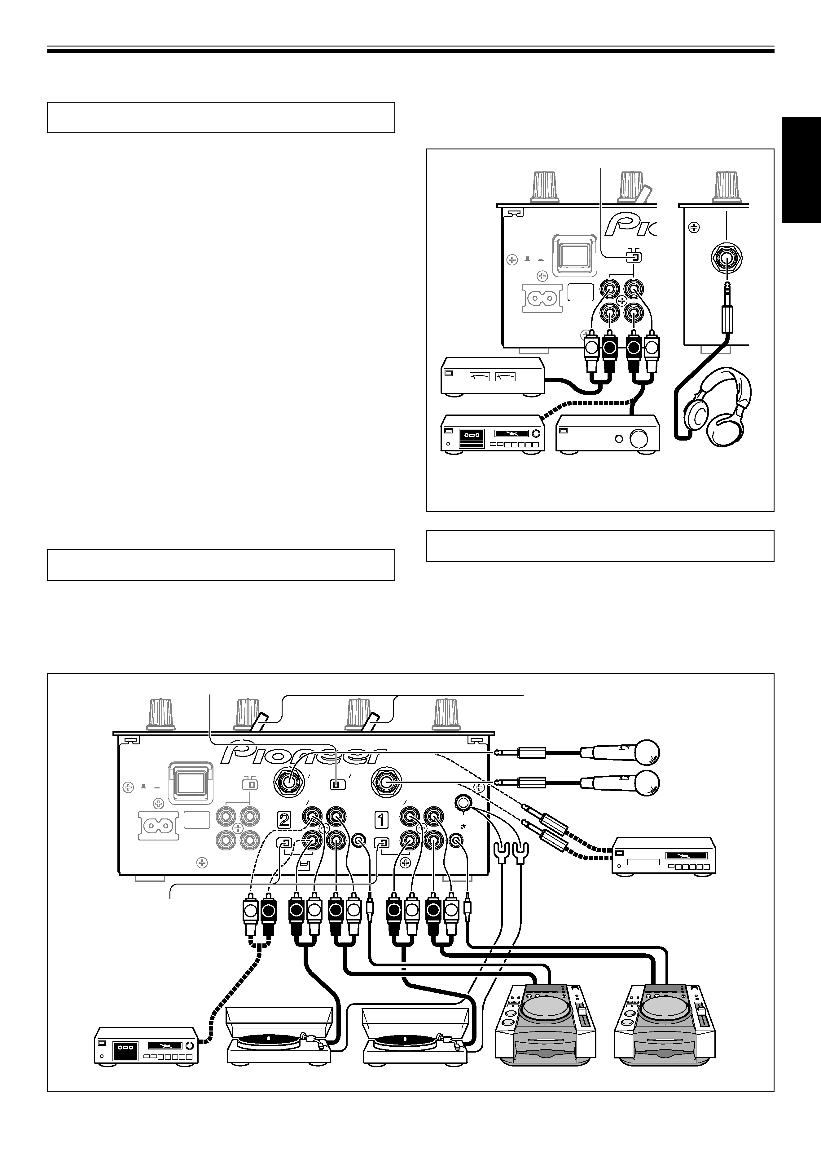
CONNECTING INPUTS
Pioneer DJ CD players
Connect a DJ CD player's audio output connectors to one of the
channel 1 to 2 CD input connectors, and connect the player's control
cable to the corresponding channel's CONTROL connector.
Set the connected channel's input selector switch to [CD].
Analog turntable
To connect an analog turntable, connect the turntable's audio output
cable to one of the channel 1 to 2 PHONO/LINE input connectors. Set
the corresponding channel's PHONO/LINE switch to [PHONO], and
set the channel's input selector switch to [PHONO/LINE]. The DJM-
400's PHONO inputs support MM cartridges. Connect the turntable's
ground wire to the DJM-400's SIGNAL GND terminal.
Connecting other devices with line level output
To use a cassette deck or other CD player, connect the component's
audio output connectors to one of the channel 1 to 2 PHONO/LINE
input connectors. Then set the corresponding channel's PHONO/
LINE switch to [LINE], and the input selector switch to [PHONO/LINE].
Microphone
The MIC1 and MIC2 jacks can be used to connect microphones with
Ø6.3 mm phone plugs. Set MIC/AUX switch to [MIC] position.
Auxiliary input connectors
The MIC1 and MIC2 jacks can also be used together as a pair of stereo
line input connectors to connect a component equipped with line
level output connectors. Connect the component's L channel to MIC1
(AUX(L)) jack and the R channel to the MIC2 (AUX(R)) jack. Then set
the MIC/AUX switch to [AUX] (this connection requires the use of
Ø6.3 mm phone plugs).
CONNECTING OUTPUTS
Master output
This unit is furnished with MASTER OUT 1 and MASTER OUT 2
output systems, both of which support the use of RCA plugs.
If the unit's STEREO/MONO switch is set to [MONO], the master
output will be a monaural combination of L+R channels.
Always turn off the power switch and disconnect the power plug from its outlet when making or changing connections.
POWER
OFF
ON
AC IN
MASTER
OUT
MONO
STEREO
2
1
L
R
L
R
LINE PHONO
LINE
PHONO
MIC2
MIC1
AUX(R)
AUX(L)
AUX
MIC
CD
CONTROL
L
R
LINE PHONO
LINE
PHONO
CD
CONTROL
SIGNAL
GND
L
R
L
R
L
R
L
R
L
R
R
L
MIC/AUX switch
Input selector switches
Microphone 2
Microphone 1
PHONO/LINE switch
Note:
Set switch to [LINE]
except when using
an analog turntable
Electronic instrument,
CD player, etc. (phone
plug connection)
Cassette deck, etc.
Analog turntable
Analog turntable
DJ CD player
DJ CD player
Headphones
The front panel PHONES jack can be used to connect headphones
with a Ø6.3 mm stereo phone plug.
POWER
OFF
ON
AC IN
MASTER
OUT
MONO
STEREO
2
1
L
R
L
R
L
R
STEREO/MONO switch
Front panel
Power amplifier
Cassette deck, etc.
(analog input recording
component)
Power amplfier
Headphones
CONNECTING THE POWER CORD
Connect the power cord last.
÷ After completing all other connections, connect the accessory
power cord to the AC inlet on the back of the player, then connect
the plug to a standard wall outlet or to the auxiliary power outlet
of your amplifier.
÷ Use only the supplied power cord.