ORDER NO.
PIONEER CORPORATION 4-1, Meguro 1-chome, Meguro-ku, Tokyo 153-8654, Japan
PIONEER ELECTRONICS SERVICE, INC. P.O. Box 1760, Long Beach, CA 90801-1760, U.S.A.
PIONEER EUROPE NV Haven 1087, Keetberglaan 1, 9120 Melsele, Belgium
PIONEER ELECTRONICS ASIACENTRE PTE. LTD. 253 Alexandra Road, #04-01, Singapore 159936
PIONEER CORPORATION 2000
DJ MIXER
RRV2323
TZZY JUNE 2000 Printed in Japan
DJM-300-S
THIS MANUAL IS APPLICABLE TO THE FOLLOWING MODEL(S) AND TYPE(S).
¶ This service manual should be used together with the following manual(s):
Model No.
Order No.
Remarks
DJM-300/SYL
RRV1711
Power Requirement
Type
Model
DJM-300-S
Remarks
NK
O
AC220V
DJM-300-S
2
1. CONTRAST OF MISCELLANEOUS PARTS
Parts marked by "NSP" are generally unavailable because they are not in our Master Spare Parts List.
The
mark found on some component parts indicates the importance of the safety factor of the part.
Therefore, when replacing, be sure to use parts of identical designation.
Screws adjacent to
mark on product are used for disassembly.
Reference Nos. indicate the pages and Nos. in the service manual for the base model.
NOTES:
When ordering resistors, first convert resistance values into code form as shown in the following examples.
Ex.1 When there are 2 effective digits (any digit apart from 0), such as 560 ohm and 47k ohm (tolerance is shown by J=5%,
and K=10%).
Ex.2 When there are 3 effective digits (such as in high precision metal film resistors).
561
473
R50
1R0
5621
560
47k
0.5
1
RD1/4PU
J
RD1/4PU
J
RN2H
K
RS1P
K
56 x 101
47 x 103
R50
1R0
561
473
5.62k
RN1/4PC
F
562 x 101
5621
CONTRAST TABLE
DJM-300-S/NK and DJM-300/SYL are constructed the same except for the following :
PACKING
P3 - 5
Packing Case
DHG1736
DHG1861
P3 - 7
Operating Instructions (English/ French/ German/
DRB1207
Not used
Italian/ Dutch/ Swedish/ Spanish/ Chinese)
P3 - 7
Operating Instructions (English)
Not used
DRB1293
P3 - 11
NSP
Caution Card 220V
ARR7003
Not used
EXTERIOR SECTION
P5 - 2
NSP
POWER SUP ASSY
DWR1260
DWR1342
*1
P5 - 4
NSP
VOLTAGE SELECT ASSY
DWR1263
Not used
P5 - 7
Cord Stopper
CM-22B
CM-22C
P5 - 9
Power Cord
PDG1003
DDG1082
P5 - 13
NSP
Rear Panel
DNC1437
DNC1528
FRONT PANEL SECTION
P7 - 24
Slider Panel
DAH1825
DAH1892
P7 - 25
Control Panel
DNB1068
DNB1070
Part No.
DJM-300/
SYL
Ref. No.
Symbol and Description
Remarks
Mark
DJM-300-S/
NK
POWER SUP ASSY
F
C
DWR1342 and DWR1260 are constructed the same except for the following :
Mark
Symbol and Description
Part No.
DWR1260
DWR1342
Remarks
J6 (Connector Assy)
Not used
DKP3535
*1
J8 (Connector Assy)
Not used
DKP3534
*1
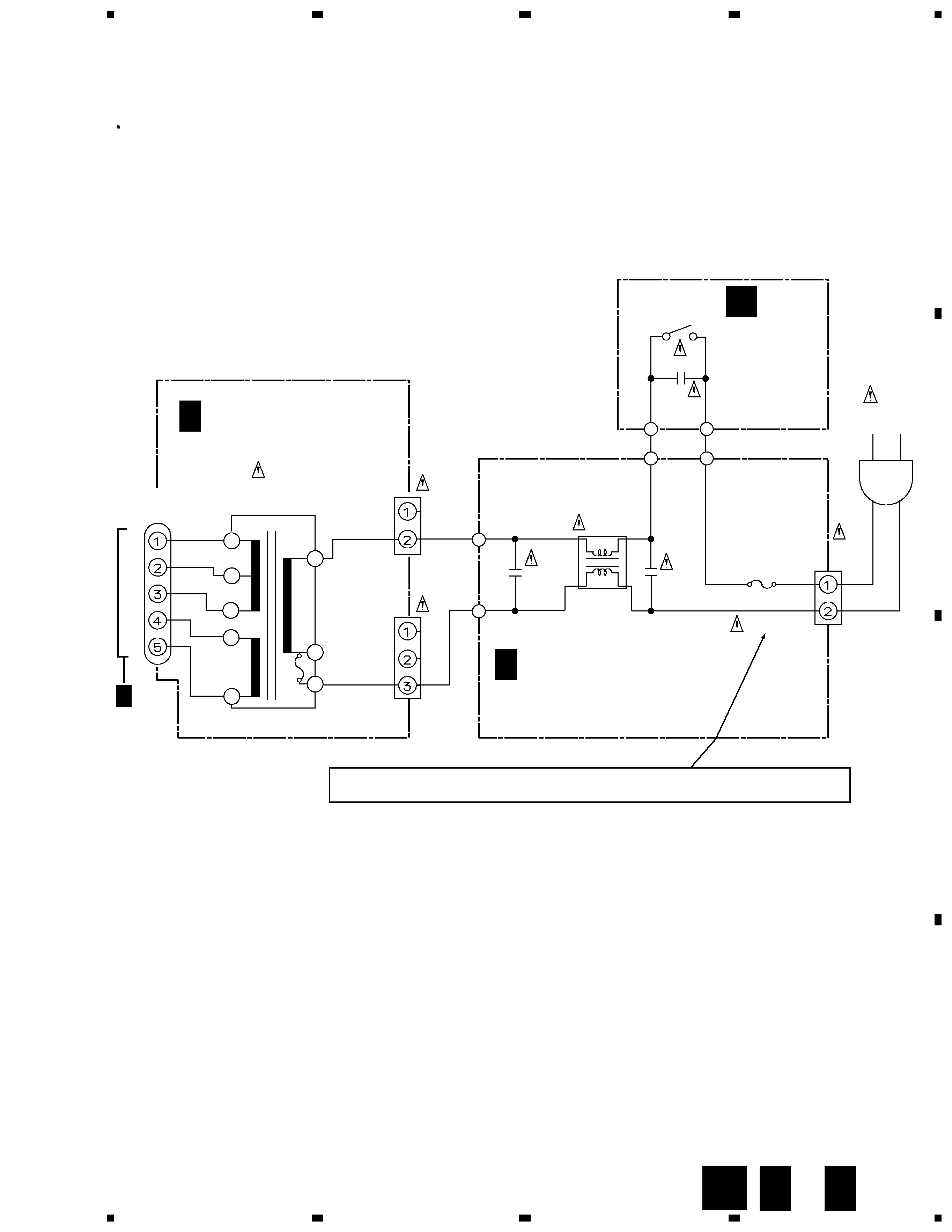
*1 : Refer to "2. SCHEMATIC DIAGRAM (2.1 POWER SW, POWER SUP and TRANS ASSYS)".
*1 : For PCB ASSEMBLIES, Refer to "CONTRAST OF PCB ASSEMBLIES" and "2. SCHEMATIC DIAGRAM".
CONTRAST OF PCB ASSEMBLIES
DJM-300-S
3
A
B
C
D
1
23
4
1
2
3
4
LIVE
NEUTRAL
H1
RKP1003
H2
RKP1003
T315mAL250V
FU701
AEK1049
CN701
CN703
CN704
J702
RKC-061
C702
0.01
ACG7020
C701
0.01
ACG7020
PW
L701
VTL-004
C703
0.01
ACG7020
J8
DKP3534
J6
DKP3535
S701
PSA-009
AC
AC
PW
J2 D8214NB2
J3 D814NB2
AC 220V
DDG1082
S1+
GND
S1-
S2+
S2-
DXWY0510E
POWER TRANSFORMER
T701 DTT1136
POWER
SW ASSY
(DWR1262)
POWER SUP ASSY
(DWR1342)
TRANS ASSY
(DWR1261)
B2P-VH
B3P5-VH
AC 220V
C F
D F
· NOTE FOR FUSE REPLACEMENT
FOR CONTINUED PROTECTION AGAINST RISK OF FIRE.
REPLACE WITH SAME TYPE AND RATINGS ONLY.
CAUTION -
B
6
5
2
9
10
11
13
14
A 3/3
CN702
2. SCHEMATIC DIAGRAM
2.1 POWERSW, POWER SUP and TRANS ASSYS
Only the differences in the schematic diagram between DJM-300-S/NK and DJM-300/SYL are shown below.
F
D
F
C
B