
Operating Instructions
DJ MIXER
DJM-1000
2
The exclamation point within an equilateral
triangle is intended to alert the user to the
presence of important operating and
maintenance (servicing) instructions in the
literature accompanying the appliance.
The lightning flash with arrowhead symbol,
within an equilateral triangle, is intended to
alert the user to the presence of uninsulated
"dangerous voltage" within the product's
enclosure that may be of sufficient
magnitude to constitute a risk of electric
shock to persons.
CAUTION:
TO PREVENT THE RISK OF ELECTRIC
SHOCK, DO NOT REMOVE COVER (OR
BACK). NO USER-SERVICEABLE PARTS
INSIDE. REFER SERVICING TO QUALIFIED
SERVICE PERSONNEL.
CAUTION
RISK OF ELECTRIC SHOCK
DO NOT OPEN
IMPORTANT
D3-4-2-1-1_En-A
READ INSTRUCTIONS -- All the safety and
operating instructions should be read before the
product is operated.
RETAIN INSTRUCTIONS -- The safety and
operating instructions should be retained for
future reference.
HEED WARNINGS -- All warnings on the product
and in the operating instructions should be
adhered to.
FOLLOW INSTRUCTIONS -- All operating and use
instructions should be followed.
CLEANING -- The product should be cleaned only
with a polishing cloth or a soft dry cloth. Never
clean with furniture wax, benzine, insecticides
or other volatile liquids since they may corrode
the cabinet.
ATTACHMENTS -- Do not use attachments not
recommended by the product manufacturer as
they may cause hazards.
WATER AND MOISTURE -- Do not use this
product near water -- for example, near a
bathtub, wash bowl, kitchen sink, or laundry
tub; in a wet basement; or near a swimming
pool; and the like.
ACCESSORIES -- Do not place this product on an
unstable cart, stand, tripod, bracket, or table.
The product may fall, causing serious injury to a
child or adult, and serious damage to the
product. Use only with a cart, stand, tripod,
bracket, or table recommended by the
manufacturer, or sold with the product. Any
mounting of the product should follow the
manufacturer's instructions, and should use a
mounting accessory recommended by the
manufacturer.
CART -- A product and cart combination should be
moved with care. Quick stops, excessive force,
and uneven surfaces may cause the product
and cart combination to overturn.
VENTILATION -- Slots and openings in the cabinet
are provided for ventilation and to ensure
reliable operation of the product and to protect
it from overheating, and these openings must
not be blocked or covered. The openings should
never be blocked by placing the product on a
bed, sofa, rug, or other similar surface. This
product should not be placed in a built-in
installation such as a bookcase or rack unless
proper ventilation is provided or the
manufacturer's instructions have been adhered
to.
POWER SOURCES -- This product should be
operated only from the type of power source
indicated on the marking label. If you are not
sure of the type of power supply to your home,
consult your product dealer or local power
company.
LOCATION The appliance should be installed in a
stable location.
NONUSE PERIODS The power cord of the
appliance should be unplugged from the outlet
when left un-used for a long period of time.
GROUNDING OR POLARIZATION
· If this product is equipped with a polarized
alternating current line plug (a plug having one
blade wider than the other), it will fit into the
outlet only one way. This is a safety feature. If
you are unable to insert the plug fully into the
outlet, try reversing the plug. If the plug should
still fail to fit, contact your electrician to replace
your obsolete outlet. Do not defeat the safety
purpose of the polarized plug.
· If this product is equipped with a three-wire
grounding type plug, a plug having a third
(grounding) pin, it will only fit into a grounding
type power outlet. This is a safety feature. If you
are unable to insert the plug into the outlet,
contact your electrician to replace your obsolete
outlet. Do not defeat the safety purpose of the
grounding type plug.
POWER-CORD PROTECTION -- Power-supply
cords should be routed so that they are not likely
to be walked on or pinched by items placed
upon or against them, paying particular
attention to cords at plugs, convenience
receptacles, and the point where they exit from
the product.
OUTDOOR ANTENNA GROUNDING -- If an
outside antenna or cable system is connected to
the product, be sure the antenna or cable
system is grounded so as to provide some
protection against voltage surges and built-up
static charges. Article 810 of the National
Electrical Code, ANSI/NFPA 70, provides
information with regard to proper grounding of
the mast and supporting structure, grounding of
the lead-in wire to an antenna discharge unit,
size of grounding conductors, location of
antenna-discharge unit, connection to
grounding electrodes, and requirements for the
grounding electrode. See Figure A.
LIGHTNING -- For added protection for this
product during a lightning storm, or when it is
left unattended and unused for long periods of
time, unplug it from the wall outlet and
disconnect the antenna or cable system. This
will prevent damage to the product due to
lightning and power-line surges.
POWER LINES -- An outside antenna system
should not be located in the vicinity of overhead
power lines or other electric light or power
circuits, or where it can fall into such power
lines or circuits. When installing an outside
antenna system, extreme care should be taken
to keep from touching such power lines or
circuits as contact with them might be fatal.
OVERLOADING -- Do not overload wall outlets,
extension cords, or integral convenience
receptacles as this can result in a risk of fire or
electric shock.
OBJECT AND LIQUID ENTRY -- Never push
objects of any kind into this product through
openings as they may touch dangerous voltage
points or short-out parts that could result in a
fire or electric shock. Never spill liquid of any
kind on the product.
SERVICING -- Do not attempt to service this
product yourself as opening or removing covers
may expose you to dangerous voltage or other
hazards. Refer all servicing to qualified service
personnel.
DAMAGE REQUIRING SERVICE -- Unplug this
product from the wall outlet and refer servicing
to qualified service personnel under the
following conditions:
· When the power-supply cord or plug is
damaged.
· If liquid has been spilled, or objects have fallen
into the product.
· If the product has been exposed to rain or water.
· If the product does not operate normally by
following the operating instructions. Adjust only
those controls that are covered by the operating
instructions as an improper adjustment of other
controls may result in damage and will often
require extensive work by a qualified technician
to restore the product to its normal operation.
· If the product has been dropped or damaged in
any way.
· When the product exhibits a distinct change in
performance -- this indicates a need for service.
REPLACEMENT PARTS -- When replacement parts
are required, be sure the service technician has
used replacement parts specified by the
manufacturer or have the same characteristics
as the original part. Unauthorized substitutions
may result in fire, electric shock, or other
hazards.
SAFETY CHECK -- Upon completion of any service
or repairs to this product, ask the service
technician to perform safety checks to
determine that the product is in proper
operating condition.
WALL OR CEILING MOUNTING -- The product
should not be mounted to a wall or ceiling.
HEAT -- The product should be situated away from
heat sources such as radiators, heat registers,
stoves, or other products (including amplifiers)
that produce heat.
GROUND
CLAMP
ELECTRIC
SERVICE
EQUIPMENT
ANTENNA
LEAD IN
WIRE
ANTENNA
DISCHARGE UNIT
(NEC SECTION 810-20)
GROUNDING CONDUCTORS
(NEC SECTION 810-21)
GROUND CLAMPS
POWER SERVICE GROUNDING
ELECTRODE SYSTEM
(NEC ART 250, PART H)
NEC -- NATIONAL ELECTRICAL CODE
Fig. A
D1-4-2-2_En
NOTE: This equipment has been tested and found to comply with the limits for a Class B digital device, pursuant to
Part 15 of the FCC Rules. These limits are designed to provide reasonable protection against harmful interference in
a residential installation. This equipment generates, uses, and can radiate radio frequency energy and, if not
installed and used in accordance with the instructions, may cause harmful interference to radio communications.
However, there is no guarantee that interference will not occur in a particular installation. If this equipment does
cause harmful interference to radio or television reception, which can be determined by turning the equipment off
and on, the user is encouraged to try to correct the interference by one or more of the following measures:
Reorient or relocate the receiving antenna.
Increase the separation between the equipment and receiver.
Connect the equipment into an outlet on a circuit different from that to which the receiver is connected.
Consult the dealer or an experienced radio/TV technician for help.
D8-10-1-2_En
WARNING
This equipment is not waterproof. To prevent a fire
or shock hazard, do not place any container filed
with liquid near this equipment (such as a vase or
flower pot) or expose it to dripping, splashing, rain
or moisture.
D3-4-2-1-3_A_En
WARNING: Handling the cord on this product or
cords associated with accessories sold with the
product will expose you to lead, a chemical known to
the State of California and other governmental
entities to cause cancer and birth defects or other
reproductive harm.
D36-P4_En
Wash hands after handling
CAUTION
PREVENT ELECTRIC SHOCK DO
NOT USE THIS (POLARIZED) PLUG
WITH AN EXTENSION CORD.
RECEPTACLE OR OTHER OUTLET
UNLESS THE BLADES CAN BE
FULLY INSERTED TO PREVENT
BLADE EXPOSURE.
ATTENTION POUR PREVENIR LES CHOCS
ELECTRIQUES NE PAS UTILISER
CETTE FICHE POLARISEE AVEC UN
PROLONGATEUR UNE PRISE DE
COURANT OU UNE AUTRE SORTIE
DE COURANT, SAUF SI LES LAMES
PEUVENT ETRE INSEREES A FOND
SANS EN LAISSER AUCUNE PARTIE
A DECOUVVERT.
D2-4-4-1_EF
This Class B digital apparatus complies with
Canadian ICES-003.
Cet appareil numérique de la Classe B est conforme
à la norme NMB-003 du Canada.
D8-10-1-3_EF
IMPORTANT NOTICE THE SERIAL NUMBER FOR
THIS EQUIPMENT IS LOCATED IN THE REAR.
PLEASE WRITE THIS SERIAL NUMBER ON YOUR
ENCLOSED WARRANTY CARD AND KEEP IN A
SECURE AREA. THIS IS FOR YOUR SECURITY.
D1-4-2-6-1_En
Information to User
Alteration or modifications carried out without
appropriate authorization may invalidate the user's
right to operate the equipment.
D8-10-2_En
POWER-CORD CAUTION
Handle the power cord by the plug. Do not pull out the
plug by tugging the cord and never touch the power
cord when your hands are wet as this could cause a
short circuit or electric shock. Do not place the unit, a
piece of furniture, etc., on the power cord, or pinch the
cord. Never make a knot in the cord or tie it with other
cords. The power cords should be routed such that they
are not likely to be stepped on. A damaged power cord
can cause a fire or give you an electrical shock. Check
the power cord once in a while. When you find it
damaged, ask your nearest PIONEER authorized
service center or your dealer for a replacement.
S002_En
Thank you for buying this Pioneer product.
Please read through these operating instructions so you will know how to operate your model properly. After you have finished
reading the instructions, put them away in a safe place for future reference.
In some countries or regions, the shape of the power plug and power outlet may sometimes differ from that shown in the explanatory
drawings. However the method of connecting and operating the unit is the same.
K015 En
CAUTION: This product satisfies FCC regulations
when shielded cables and connectors are used to
connect the unit to other equipment. To prevent
electromagnetic interference with electric appliances
such as radios and televisions, use shielded cables
and connectors for connections.
D8-10-3a_En

3
FEATURES
CONTENTS
1 High sound quality design
Analog signals are transmitted via the shortest path and converted
to digital signals by a 96 kHz sampling, 24 bit, high-quality A/D
converter, thus passing the signals to the digital mixing stage
under optimum conditions.
Through the use of a 32 bit DSP, mixing is achieved with zero
sound quality degradation, and together with simultaneous ideal
filtering, optimum sound is produced for professional DJs
working in clubs.
To get the most from these features, a great deal of care has been
paid to perfecting the sound quality, including a high-rigidity
chassis to cut down unnecessary vibrations that might affect the
sound, together with a high-performance power section using an
R-core transformer that supports bass quality, thus creating clear
and powerful sound ideal for club performances.
2 3 band isolator
Built-in 3-band isolator capable of producing level control
+6 dB to
on each bandwidth.
The sharp operation feel allows the realization of a wide variety of
DJ performances.
3 2-system, 3-type SEND/RETURN
A 2-system, 3-type SEND/RETURN (PRE INSERT/POST INSERT/
AUX) is provided to allow multiple connection variations with
other external devices, such as effectors and samplers, thus
widening the range of DJ play potential.
4 Fader curve adjust
The fader curve adjust allows adjustment not only the cross fader
curve (as on former models), but also of channel fader curve.
Both faders' functions can be adjusted within 17 steps, so that DJs
can customize the settings to their own preferred settings.
5 Digital IN/OUT
Using digital input connectors provided for each of the sampling
rates (44.1/48/96 kHz), a system can be built in which no sound
quality degradation occurs when connecting to external digital
devices.
A DIGITAL OUT connector with 24 bit/96 kHz sampling rate is
provided, facilitating recording at studios and other situations
demanding high sound quality.
Supports only linear PCM.
6 MIDI OUT
MIDI signals can be output to allow MIDI control of external
devices.
7 Digital link function
Multiple functions can be performed by using digital link cables to
connect other PIONEER DJ CD players, DJ effectors and AV
mixers.
8 Other features
÷ By using a control cable to connect the unit to a PIONEER DJ-
use CD player, playback can be started on the CD player in
automatic linkage to operation of the fader ("fader start play").
÷ Built-in "3-band equalizer" enabling level control within range
+6 dB to 26 dB at each bandwidth.
÷ Features "2-band booth EQ" for control of booth monitor
response, thus facilitating booth monitoring by the DJ.
÷ Built-in "cross fader assign" function, enabling more flexible
assigning of each channel's input to the cross fader.
÷ Built-in "TALK OVER function" automatically lowers track
volume during MIC-input.
FEATURES ................................................................... 3
CONFIRM ACCESSORIES ........................................... 3
CAUTIONS REGARDING HANDLING ........................ 4
BEFORE USING
CONNECTIONS ............................................................ 5
CONNECTION PANEL ........................................... 5
POWER CORD CONNECTION ............................... 6
CONNECTING TO THE INPUT CONNECTORS ... 6
CONNECTING TO THE EFFECTOR AND
OUTPUT CONNECTORS ....................................... 7
MIDI CONNECTORS .............................................. 7
CONNECTING MICROPHONES, HEADPHONES ... 8
DIGITAL LINK CONNECTIONS ............................. 8
PART NAMES AND FUNCTIONS ............................... 9
OPERATIONS
OPERATIONS ............................................................. 13
BASIC OPERATIONS ........................................... 13
FADER CURVE ADJUSTMENTS ......................... 13
FADER START FUNCTION .................................. 14
USING EXTERNAL EFFECTORS ......................... 14
DIGITAL LINK FUNCTION ................................... 15
OTHER
TROUBLESHOOTING ................................................ 16
SPECIFICATIONS ....................................................... 17
BLOCK DIAGRAM ...................................................... 18
CONFIRM ACCESSORIES
Operating Instructions ........................................................... 1
Power cord ............................................................................. 1
Warranty ................................................................................. 1

4
Location
Install the unit in a well-ventilated location where it will not
be exposed to high temperatures or humidity.
÷ Do not install the unit in a location which is exposed to
direct rays of the sun, or near stoves or radiators. Excessive
heat can adversely affect the cabinet and internal
components. Installation of the unit in a damp or dusty
environment may also result in a malfunction or accident.
(Avoid installation near cookers etc., where the unit may be
exposed to oily smoke, steam or heat.)
÷ When the unit is used inside a carrying case or DJ booth,
separate it from the walls or other equipment to improve
heat radiation.
Installing the DJM-1000 in an EIA rack
The screw holes on the front panel of the DJM-1000 are
designed for use in attaching the unit to a 19-inch EIA rack.
÷ Attach the unit to the rack using screws of the appropriate
size (screws not provided with the unit).
÷ When installing the unit in a rack, take care to avoid
pinching your fingers.
Note
÷ Never place this unit directly above a power amplifier, as
the heat given off by the amplifier might result in damage
to the unit. Placing the unit directly above a power
amplifier might also result in ham radio signals being
picked up or in other types of interference.
÷ Allow at least 1U (43.7 mm) space between this component
and the one mounted above it, so as to assure that the
cords connected to this unit's input/output connectors and
terminals do not touch the component above.
÷ Always be sure to remove the unit from its rack before
shipping.
÷ When moving the unit while still installed in its rack,
exercise caution to avoid subjecting the unit to shocks or
vibration.
Condensation
When this unit is brought into a warm room from previously
cold surroundings or when the room temperature rises
sharply, condensation may form inside, and the unit may not
be able to attain its full performance. In cases like this, allow
the unit to stand for about an hour or raise the room
temperature gradually.
Cleaning the Unit
÷ Use a polishing cloth to wipe off dust and dirt.
÷ When the surfaces are very dirty, wipe with a soft cloth
dipped in some neutral cleanser diluted five or six times
with water and wrung out well, then wipe again with a dry
cloth. Do not use furniture wax or cleaners.
÷ Never use thinners, benzene, insecticide sprays or other
chemicals on or near this unit, since these will corrode the
surfaces.
CAUTIONS REGARDING HANDLING
5
BEFORE USING (CONNECTIONS)
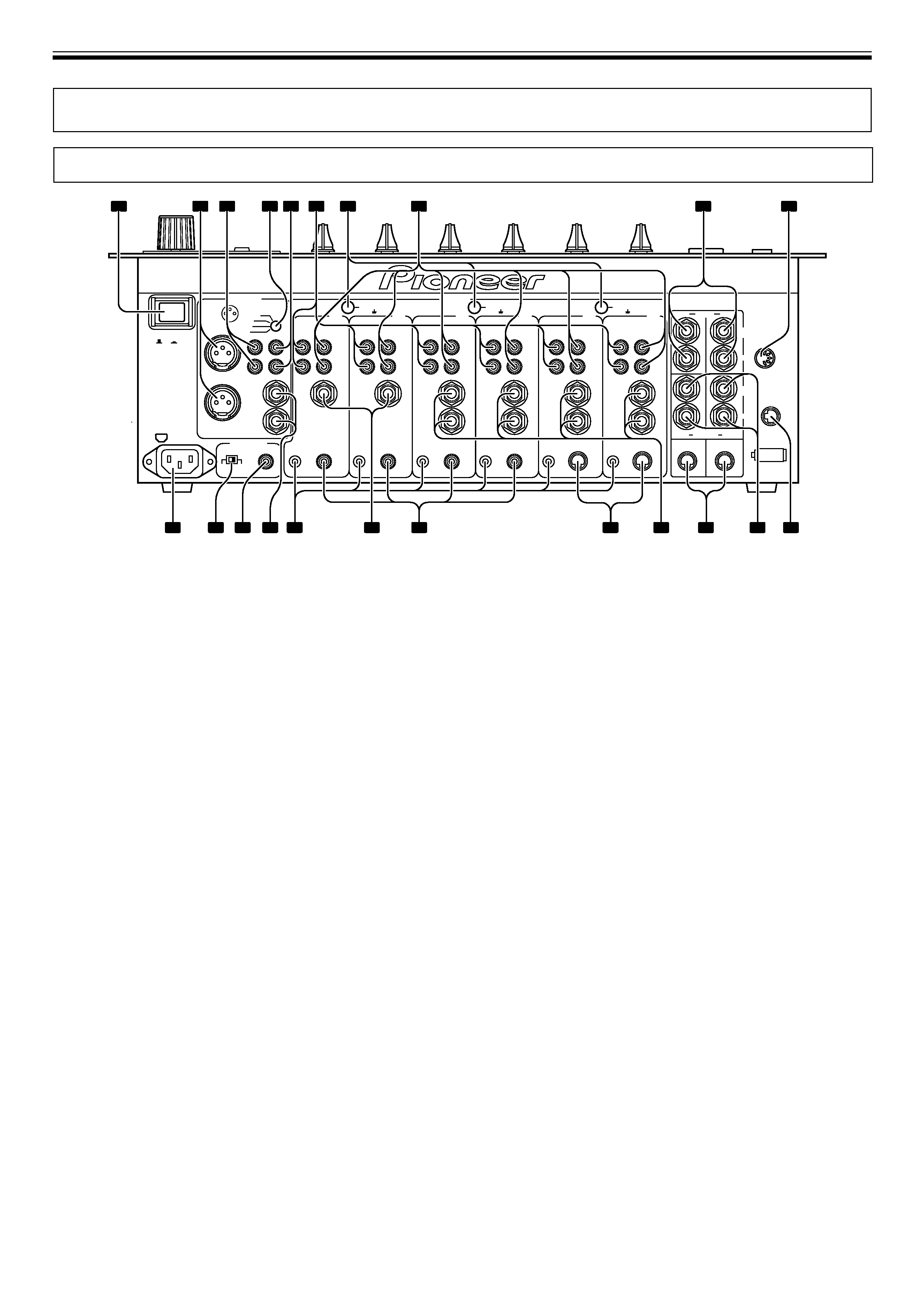
CONNECTION PANEL
MIDI OUT
INPUT
OUTPUT
POWER
AC IN
VISUAL
(MONO)
(MONO)
(MONO)
L
L
L
R
R
L
R
R
2 RETURN 1
EFX 1
EFX 2
CONTROL
SOUND 1
2
SEND
1
SIGNAL GND.
PHONO
LINE
(MONO)
L
R
LINE
(MONO)
L
R
LINE
(MONO)
L
R
LINE
1
SIGNAL GND.
SIGNAL GND.
L
R
CONTROL
SOUND 2
PHONO
2
L
R
CONTROL
DIGITAL
PHONO
3
L
R
CONTROL
DIGITAL
PHONO
4
L
R
CONTROL
DIGITAL
PHONO
5
L
L
L
BOOTH
R
R
L
R
R
48k
96k
fs(Hz)
CONTROL
DIGITAL
DIGITAL OUT
PHONO
MASTER 1
MASTER 2
REC
SUBMIC
SUBMIC
CD / LINE
CD / LINE
CD / LINE
CD / LINE
CD / LINE
CD / LINE
6
MASTER ATT.
12dB
6dB
3dB
0dB
3
COLD
1
2
GND
HOT
OFF
ON
(TRS)
1
2
3
4
5
6
7
8
9
10
11
12
13
14
15
16
17
18
19
20
21
22
1. POWER switch
2. MASTER output connector 1 (MASTER 1)
XLR type balanced output (male connector).
3. MASTER output connector 2 (MASTER 2)
RCA type unbalanced output.
4. MASTER output attenuator dial (MASTER ATT.)
Attenuates the output level of MASTER 1 and MASTER 2 output.
The level of attenuation can be chosen from 0 dB, 3 dB, 6 dB,
12 dB.
5. Recording output connectors (REC)
RCA type output connector for recording.
6. PHONO input connectors
RCA type phono level (for MM cartridge) input connectors.
Do not use for input of line level signals.
7. Signal grounding terminal (SIGNAL GND)
Use to connect grounding wire from analog player.
Not a terminal for safety grounding.
8. CD/LINE input connectors
RCA type line level input connectors.
Use to connect DJ CD players and/or line level output devices.
9. SEND output connectors (SEND 1, 2)
Ø6.3 mm phone type output connectors.
Use to connects input connectors from external effectors, etc.
When only the L channel is connected, a monaural signal of L+R is
output.
10. MIDI output connector (MIDI OUT)
DIN type output connector.
Connects with other MIDI devices (P.7).
11. VISUAL link connector
When a digital link cable is used to connect the unit to a PIONEER
video mixer (switcher) supporting digital-linkage, the video
mixer's cross fader can be controlled using the cross fader of the
DJM-1000.
12. RETURN connectors (RETURN 1, 2)
Ø6.3 mm phone type output connectors.
Connect to input connectors of external effectors, etc.
When only the L channel is connected, the input in the L channel
will be input into the R channel.
13. EFX link input/output connectors (EFX 1, 2)
When a digital-link cable is used to connect the unit to a PIONEER
DJ effector supporting digital linkage (EFX-1000), SEND/RETURN
connections are performed at once digitally, and functions such as
fader effect are also enabled.
14. LINE input connectors
Ø6.3 mm phone type line level connectors.
When only the L channel is connected, the input to the L channel
will also be input into the R channel.
15. CDJ link input connectors (SOUND 1, 2)
When a digital-link cable is used to connect the unit to a PIONEER
DJ CD player supporting digital linkage, the digital audio
connections and control cable connections are performed at once,
and functions such as BPM synchro are also enabled.
16. DIGITAL input connectors
RCA type digital coaxial input connectors.
Connect to digital coaxial output connectors of DJ CD player, etc.
17. SUBMIC input connectors
Ø6.3 mm phone type microphone input connectors.
Utilizes the DJM-1000's channels 5 and 6 as microphone input
channels.
18. CONTROL connectors
Ø3.5 mm mini phone-type input connector for connecting control
cable to DJ CD player.
Allows use of the DJM-1000's fader function to control start/stop
of a connected DJ CD player.
19. BOOTH monitor output connectors
Ø 6.3 mm phone type output connectors for booth monitor.
Changes the volume with the BOOTH MONITOR dial (LEVEL),
unaffected to the MASTER fader (since output is TRS, both
balanced and unbalanced outputs are supported).
20. Digital output connector (DIGITAL OUT)
RCA type digital coaxial output connector.
Digital master output.
21. Sampling frequency selector switch (48k/96k)
Chooses the sampling frequency of the digital output (96 kHz or
48 kHz).
22. Power inlet connector (AC IN)
Connect to AC outlet plug with the provided power cord.
CONNECTIONS