ORDER NO.
PIONEER ELECTRONIC CORPORATION 4-1, Meguro 1-Chome, Meguro-ku, Tokyo 153-8654, Japan
PIONEER ELECTRONICS SERVICE, INC. P.O. Box 1760, Long Beach, CA 90801-1760, U.S.A.
PIONEER ELECTRONIC (EUROPE) N.V. Haven 1087, Keetberglaan 1, 9120 Melsele, Belgium
PIONEER ELECTRONICS ASIACENTRE PTE. LTD. 501 Orchard Road, #10-00 Wheelock Place, Singapore 238880
PIONEER ELECTRONIC CORPORATION 1998
STEREO DOUBLE CASSETTE DECK
RRV2038
TDZE OCT. 1998 Printed in Japan
CT-W505R
1. CONTRAST OF MISCELLANEOUS PARTS ..... 2
2. SCHEMATIC DIAGRAM ..................................... 5
3. PCB CONNECTION DIAGRAM ......................... 7
CONTENTS
Refer to the service manual RRV1475 for CT-W505R/KUXJ.
HYXJ7
AC220230V
AC230240V,
HVXJ7
AC230240V
AC220230V,
: Alter the wiring of the power-supply block at the primary winding of Power transformer referring to
the Line Voltage Selection described in Service Manual.
THIS MANUAL IS APPLICABLE TO THE FOLLOWING MODEL(S) AND TYPE(S).
The voltage can be converted by the following method.
Power Requirement
Type
Model
CT-W505R
CT-W505R
2
NSP
MOTHER UNIT
RWM1817
RWM2054
RWM2054
P41
MAIN UNIT
RWZ3721
RWZ4323
RWZ4323
P42
SUB UNIT
RWZ3722
RWZ4324
RWZ4324
P44
NSP
TRANSFORMER 2 UNIT
RWZ3723
RWZ4325
RWZ4325
1
P45
Strain Relief
CM22C
CM22B
CM22B
P46
FU1001, FU1002 (Fuse, 1.5A)
REK1059
Not used
Not used
P46
FU1, FU2 (Fuse, 1.6A)
Not used
REK1024
REK1024
P47
AC Power Cord
PDG1015
PDG1058
PDG1055
2 No. 1
P49
Power Transformer (AC120V)
RTT1223
Not used
Not used
P49
Power Transformer (AC220230V)
Not used
RTT1276
RTT1276
P410
1 Mechanism Unit
RYM1237
RYM1261
RYM1261
P411
2 Mechanism Unit
RYM1238
RYM1262
RYM1262
P412
Rubber Sheet (for front side)
AEB1111
Not used
Not used
P413
Foot Assy (for rear side)
AEC1531
Not used
Not used
P428
Power Knob
RAC1883
RAC2110
RAC2110
2 No. 2
P431
FL Lens
RAH2686
RAH2688
RAH2688
P432
Front Panel
RAH2689
RAH2873
RAH2873
P436
Name Plate
RAM1007
PAM1791
PAM1791
P438
Rear Panel
RNA2028
RNA2215
RNA2216
P440
Connection Cord Assy
RDE1002
RDE1026
RDE1026
P442
Operating Instructions (English)
RRB1170
Not used
RRB1187
Operating Instructions
Not used
RRD1205
Not used
(French/Italian/Dutch/Swedish/
Spanish/Portuguese)
Operating Instructions
Not used
RRE1169
Not used
(English/German)
P445
Packing Case
RHG1703
RHG1881
RHG1882
P451
65 Label
ORW1069
Not used
Not used
P463
NSP
Fuse Caution Label
RRW111
Not used
Not used
P464
NSP
Transformer 1 PCB
RNZ3050
RNZ3321
RNZ3321
P465
NSP
Warranty Card
ARY1051
ARY7022
ARY7022
NSP
Transformer Cover PCB
Not used
RNZ3323
RNZ3323
3
1. CONTRAST OF MISCELLANEOUS PARTS
NOTES :
÷ Parts marked by " NSP " are generally unavailable because they are not in our Master Spare Parts List.
÷ The
mark found on some component parts indicates the importance of the safety factor of the part.
Therefore, when replacing, be sure to use parts of identical designation.
÷ When ordering resistors, first convert resistance values into code form as shown in the following examples.
Ex. 1
When there are 2 effective digits (any digit apart from 0), such as 560 ohm and 47k ohm (tolerance is shown by
J = 5%, and K = 10%).
560
= 56 × 101= 561 ................................................... RD1/4PU 5 6 1 J
47k
= 47 × 10 3 = 473 .................................................. RD1/4PU 4 7 3 J
0.5
= R50 ...................................................................... RN2H Â 5 0 K
1
= 1R0 ......................................................................... RS1P 1 Â 0 K
Ex. 2
When there are 3 effective digits (such as in high precision metal film resistors).
5.62k
= 562 × 10 1 = 5621 ........................................... RN1/4PC 5 6 2 1 F
÷ Reference Nos. indicate the pages and Nos. in the service manual for the base model.
CONTRAST TABLE
Part No.
Remarks
CT-W505R
CT-W505R
CT-W505R
KUXJ
HYXJ7
HVXJ7
CT-W505R/HYXJ7, HVXJ7 and CT-W505R/KUXJ are constructed the same except for the following:
Ref.
No.
Mark
Symbol and Description
CT-W505R
3
Fuse Holder
HYXJ7 type
HVXJ7 type
HVXJ7 type Only
1
1
3
2
4
6
7
9
8
5
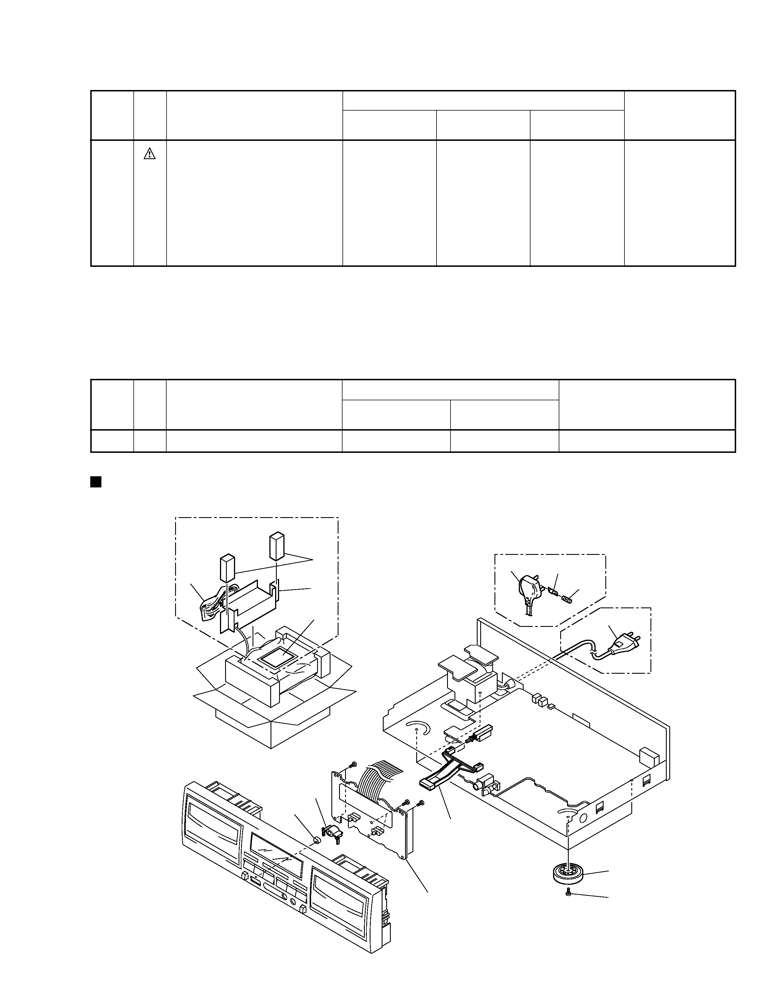
BBZ30P080FZK
SUB UNIT
LED
Lens
MAIN UNIT
S1000
P96
MTR MAIN BLK
RXM1081
RXM1075
Fuse (5A) (for AC power cord)
Not used
Not used
PEK1003
2 No. 3
LED Lens Cover
Not used
RNK2206
RNK2206
2 No. 4
Insulator (for front and rear side)
Not used
PNW1912
PNW1912
2 No. 5
Spacer A
Not used
Not used
RHC1032
2 No. 6
Spacer B
Not used
Not used
RHC1033
2 No. 7
Caution Card
Not used
Not used
RRN1001
2 No. 8
Vinyl Bag (115
× 270 × 0.05)
Not used
Not used
Z21013
2 No. 9
Part No.
Remarks
CT-W505R
CT-W505R
CT-W505R
KUXJ
HYXJ7
HVXJ7
Ref.
No.
Mark
Symbol and Description
*1: Although RWZ4325 and RWZ3723 are different in part number, they have same service parts.
*2: The numbers in the remarks column correspond to the numbers on the " EXPLODED VIEWS ".
*3: Refer to " 2. SCHEMATIC DIAGRAM".
EXPLODED VIEWS
1 Mechanism Unit and 2 Mechanism Unit
RYM1261, RYM1262 and RYM1237, RYM1238 are constructed the same except for the following:
Part No.
Remarks
Symbol and Description
RYM1237,
RYM1238
RYM1261,
RYM1262
Ref.
No.
Mark
CT-W505R
4
IC501
PD5350A
PD5505A
D503
1SS254
Not used
S1000
Not used
RSA1002
1
F103F106, F301F304
Not used
DTF1067
1
C111, C112, C180C182, C185, C191,
CEAS4R7M50
CEAT4R7M50
C198, C199, C331, C332, C468
C119, C120, C183, C325, C327, C338,
CEAS470M16
CEAT470M16
C340, C501, C1013
C133C136, C186, C341, C342, C701,
CEAS1R0M50
CEAT1R0M50
C702, C708
C171, C172, C203, C204, C315, C316,
CEAS100M50
CEAT100M50
C323, C324, C328, C329, C465, C1008
C175, C176, C201, C202
CFTXA103J50
CFTYA103J50
C184, C187C189
CEAS101M10
CEAT101M10
C311, C312, C349, C350, C464
CEASR10M50
CEATR10M50
C313, C314
CFTXA683J50
CFTYA683J50
C353, C354
Not used
CCCSL101J50
1
C401
CQPA682J2A
CQMA682J50
C402
CFTXA223J50
CFTYA223J50
C406C408
CEAS470M16
CEAL470M16
C467
CEAS4R7M50
CEAL4R7M16
C601, C602
CEASR22M50
CEATR22M50
C603, C604
CEAS101M16
CEAT101M16
C605, C1006, C1007, C1015
CEAS331M16
CEAT331M16
C802, C852
Not used
CCSQSL330J50
1
C1005
RCH1116
RCH1120
(4700/25)
(4700/35)
C1009
CEAS220M16
CEAT220M25
C1011
CEAS221M35
CEAT221M35
C1012
CEAS330M35
CEAT330M35
C1016
CEAS102M6R3
CEAT102M6R3
C1020C1023
Not used
CKCYF473Z50
1
VR101VR104 (22 k
B)
RCP1046
VCP1158
VR801 (2.2 k
B)
RCP1019
VCP1123
VR802, VR851 (1 k
B)
RCP1044
VCP1151
R127R130, R309R312
RS1/10S0R0J
Not used
J1002
Not used
D20PWW0815E
1
CONTRAST OF PCB ASSEMBLIES
MAIN UNIT
RWZ4323 and RWZ3721 are constructed the same except for the following:
1: Refer to "2. SCHEMATIC DIAGRAM".
Mark
Remarks
Symbol and Description
Part No.
RWZ3721
RWZ4323
SUB UNIT
RWZ4324 and RWZ3722 are constructed the same except for the following:
D1515
SEL6210S
Not used
S1528 (POWER STANDBY/ON)
RSG1034
Not used
R1501
RD1/4PU181J
Not used
Mark
Remarks
Symbol and Description
Part No.
RWZ3722
RWZ4324
CT-W505R
5
A
B
C
D
1
23
4
1
2
3
4
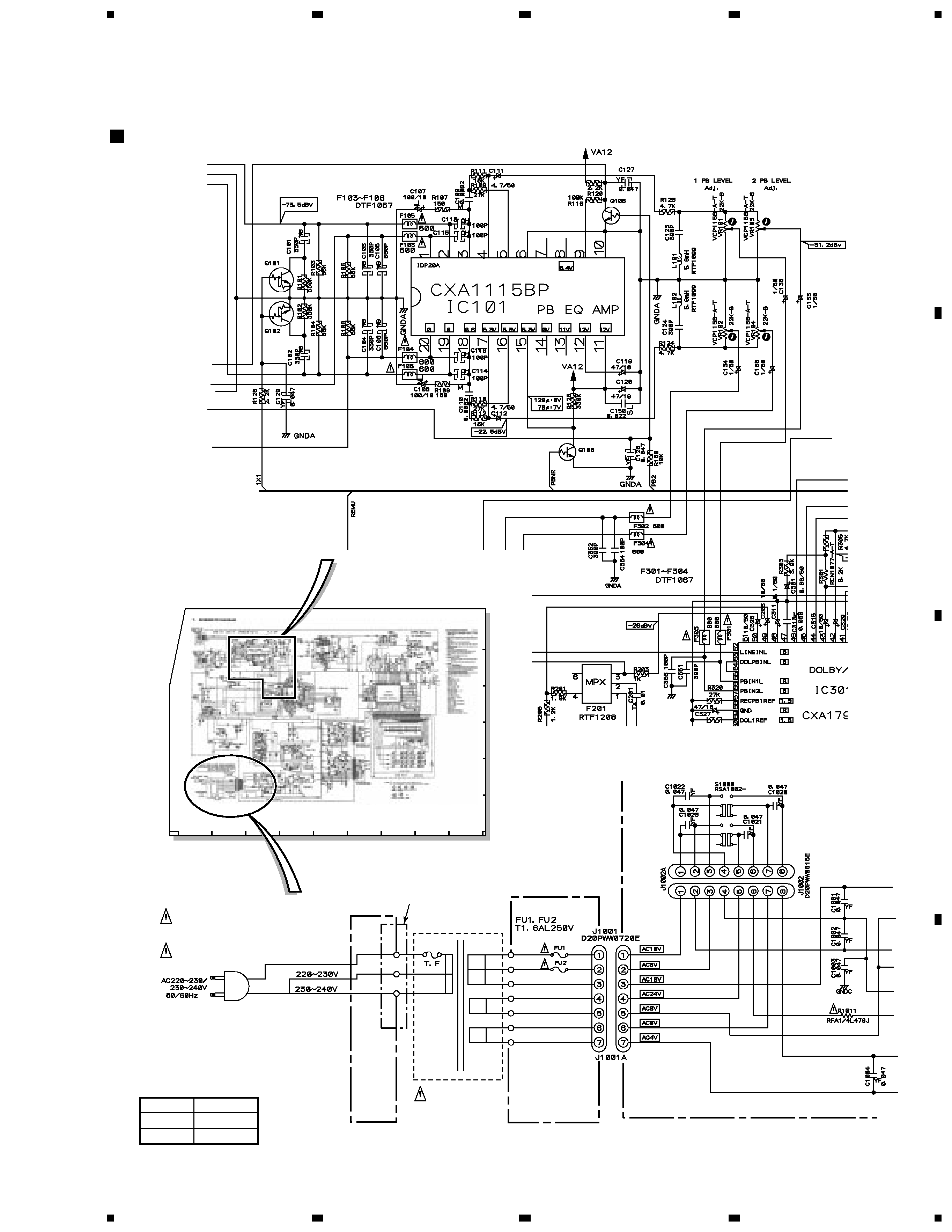
2. SCHEMATIC DIAGRAM
Note: When ordering service parts, be sure to refer to "EXPLODED VIEWS AND PARTS LIST" or "PCB PARTS LIST".
TRANSFORMER
2 UNIT
(RWZ4325)
MAIN UNIT
(RWZ4323)
MAIN UNIT
(RWZ4323)
TRANSFORMER 1 PCB
(RNZ3321)
TRANSFORMER Cover PCB
(RNZ3323)
5
NEUTRAL
LIVE
POWER
TRANSFORMER
RTT1276
AC POWER CORD
PDG1058 (HYXJ7 type)
PDG1055 (HVXJ7 type)
FUSE (5A): PEK1003
(HVXJ7 type Only)
3
1
LINE Voltage Selection
Line voltage can be changed following modification:
1. Disconnect the AC power cord.
2. Remove the cover.
3. Change the connection of TRANSFORMER 1
PCB primary pins.
4. Stick a line voltage label on the rear panel.
Part No.
Description
AAX193
220V label
AAX192
240V label
SCHEMATIC DIAGRAM (1/2)