ORDER NO.
PIONEER ELECTRONIC CORPORATION 4-1, Meguro 1-Chome, Meguro-ku, Tokyo 153-8654, Japan
PIONEER ELECTRONICS SERVICE, INC. P.O. Box 1760, Long Beach, CA 90801-1760, U.S.A.
PIONEER ELECTRONIC (EUROPE) N.V. Haven 1087, Keetberglaan 1, 9120 Melsele, Belgium
PIONEER ELECTRONICS ASIACENTRE PTE. LTD. 253 Alexandra Road, #04-01, Singapore 159936
PIONEER ELECTRONIC CORPORATION 1999
c
CT-IS21
RRV2142
1. SAFETY INFORMATION ...................................... 2
2. EXPLODED VIEWS AND PARTS LIST ................ 3
3. BLOCK DIAGRAM AND SCHEMATIC DIAGRAM .. 10
4. PCB CONNECTION DIAGRAM .......................... 18
5. PCB PARTS LIST ............................................... 24
6. ADJUSTMENT .................................................... 27
CONTENTS
7. GENERAL INFORMATION ................................ 31
7.1 DIAGNOSIS ................................................. 31
7.1.1 POWER ON SEQUENCE ...................... 31
7.1.2 DISASSEMBLY ...................................... 32
7.2 PARTS ......................................................... 33
7.2.1 IC ............................................................ 33
8. PANEL FACILITIES AND SPECIFICATIONS .... 34
T IZM MAY 1999 Printed in Japan
Type
Model
Power Requirement
CT-IS21
MY
AC220-230V
NV
AC230V
RBD
AC110-127V/220-240V
With the voltage selector
THIS MANUAL IS APPLICABLE TO THE FOLLOWING MODEL(S) AND TYPE(S).
STEREO CASSETTE DECK
The Voltage can be converted by
the following method.
2
CT-IS21
1. SAFETY INFORMATION
This service manual is intended for qualified service technicians ; it is not meant for the casual do-it-
yourselfer. Qualified technicians have the necessary test equipment and tools, and have been trained
to properly and safely repair complex products such as those covered by this manual.
Improperly performed repairs can adversely affect the safety and reliability of the product and may
void the warranty. If you are not qualified to perform the repair of this product properly and safely, you
should not risk trying to do so and refer the repair to a qualified service technician.
WARNING
This product contains lead in solder and certain electrical parts contain chemicals which are known to the state of California to cause
cancer, birth defects or other reproductive harm.
Health & Safety Code Section 25249.6 Proposition 65
NOTICE
(FOR CANADIAN MODEL ONLY)
Fuse symbols
(fast operating fuse) and/or
(slow operating fuse) on PCB indicate that replacement parts must
be of identical designation.
REMARQUE
(POUR MODÈLE CANADIEN SEULEMENT)
Les symboles de fusible
(fusible de type rapide) et/ou
(fusible de type lent) sur CCI indiquent que les pièces
de remplacement doivent avoir la même désignation.
ANY MEASUREMENTS NOT WITHIN THE LIMITS
OUTLINED ABOVE ARE INDICATIVE OF A POTENTIAL
SHOCK HAZARD AND MUST BE CORRECTED BEFORE
RETURNING THE APPLIANCE TO THE CUSTOMER.
2. PRODUCT SAFETY NOTICE
Many electrical and mechanical parts in the appliance
have special safety related characteristics. These are
often not evident from visual inspection nor the protection
afforded by them necessarily can be obtained by using
replacement components rated for voltage, wattage, etc.
Replacement parts which have these special safety
characteristics are identified in this Service Manual.
Electrical components having such features are identified
by marking with a
on the schematics and on the parts list
in this Service Manual.
The use of a substitute replacement component which does
not have the same safety characteristics as the PIONEER
recommended replacement one, shown in the parts list in
this Service Manual, may create shock, fire, or other hazards.
Product Safety is continuously under review and new
instructions are issued from time to time. For the latest
information, always consult the current PIONEER Service
Manual. A subscription to, or additional copies of, PIONEER
Service Manual may be obtained at a nominal charge from
PIONEER.
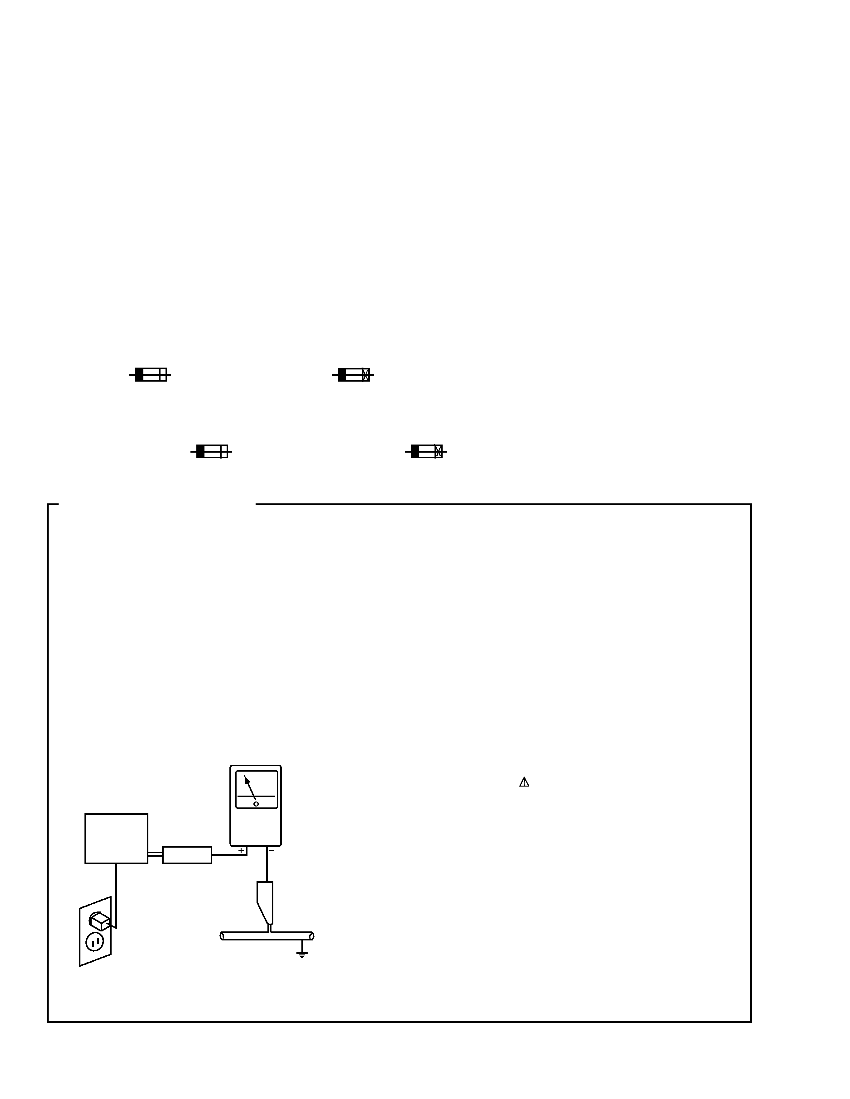
1. SAFETY PRECAUTIONS
The following check should be performed for the
continued protection of the customer and service
technician.
LEAKAGE CURRENT CHECK
Measure leakage current to a known earth ground (water
pipe, conduit, etc.) by connecting a leakage current tester
such as Simpson Model 229-2 or equivalent between the
earth ground and all exposed metal parts of the appliance
(input/output terminals, screwheads, metal overlays, control
shaft, etc.). Plug the AC line cord of the appliance directly
into a 120V AC 60Hz outlet and turn the AC power switch
on. Any current measured must not exceed 0.5mA.
(FOR USA MODEL ONLY)
Leakage
current
tester
Reading should
not be above
0.5mA
Device
under
test
Test all
exposed metal
surfaces
Also test with
plug reversed
(Using AC adapter
plug as required)
Earth
ground
AC Leakage Test
3
CT-IS21
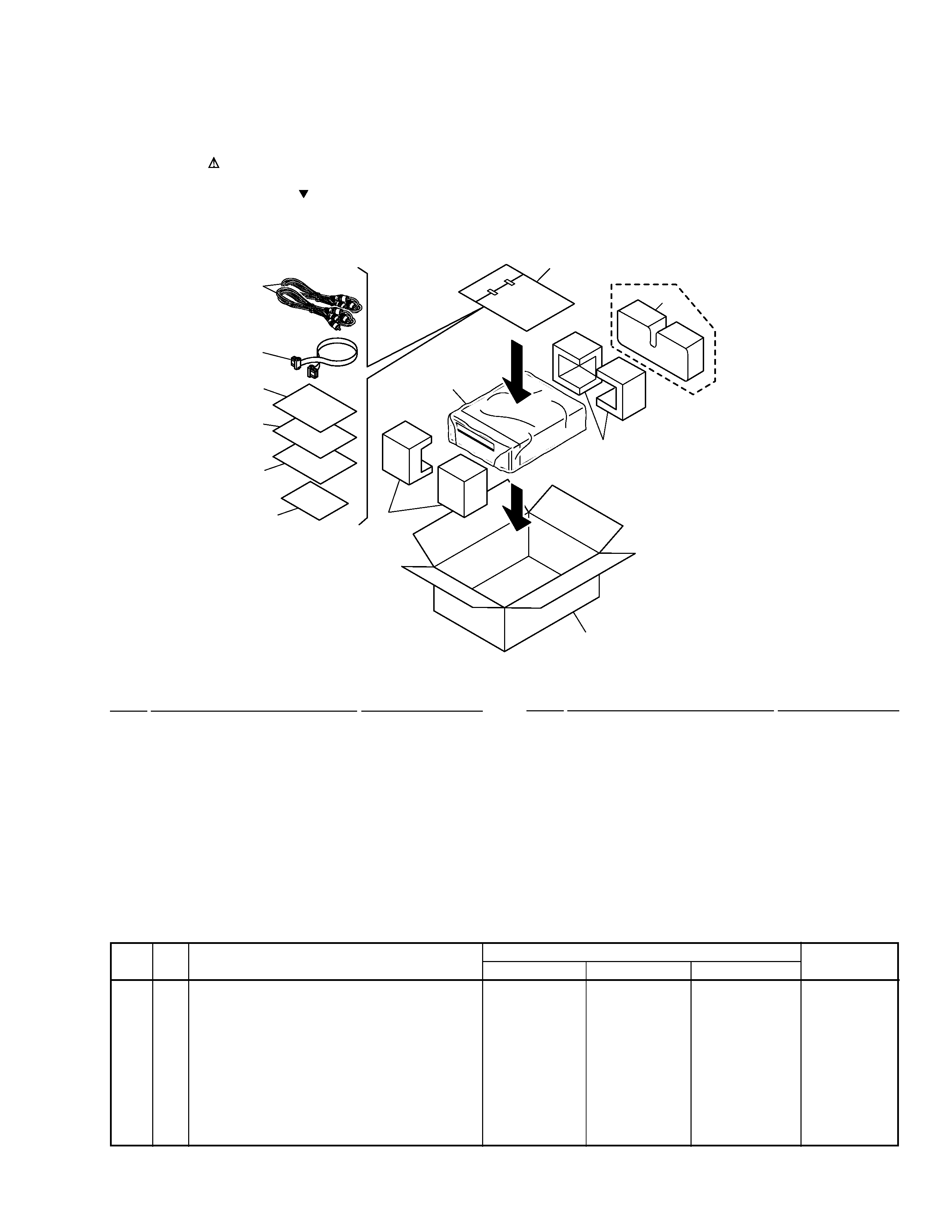
2.1 PACKING
1
F Pad
AHA7267
2
R Pad
AHA7268
3
Packing Case
See Contrast table (2)
4
Mirror Mat Sheet
Z23-026
5
System Cable
ADE7032
6
RCA Pin-plug Stereo Cable
ADE7034
7
Operating Instructions
See Contrast table (2)
(Spanish/Portuguese/Dutch/Swedish)
(1) PACKING PARTS LIST
Mark No.
Description
Part No.
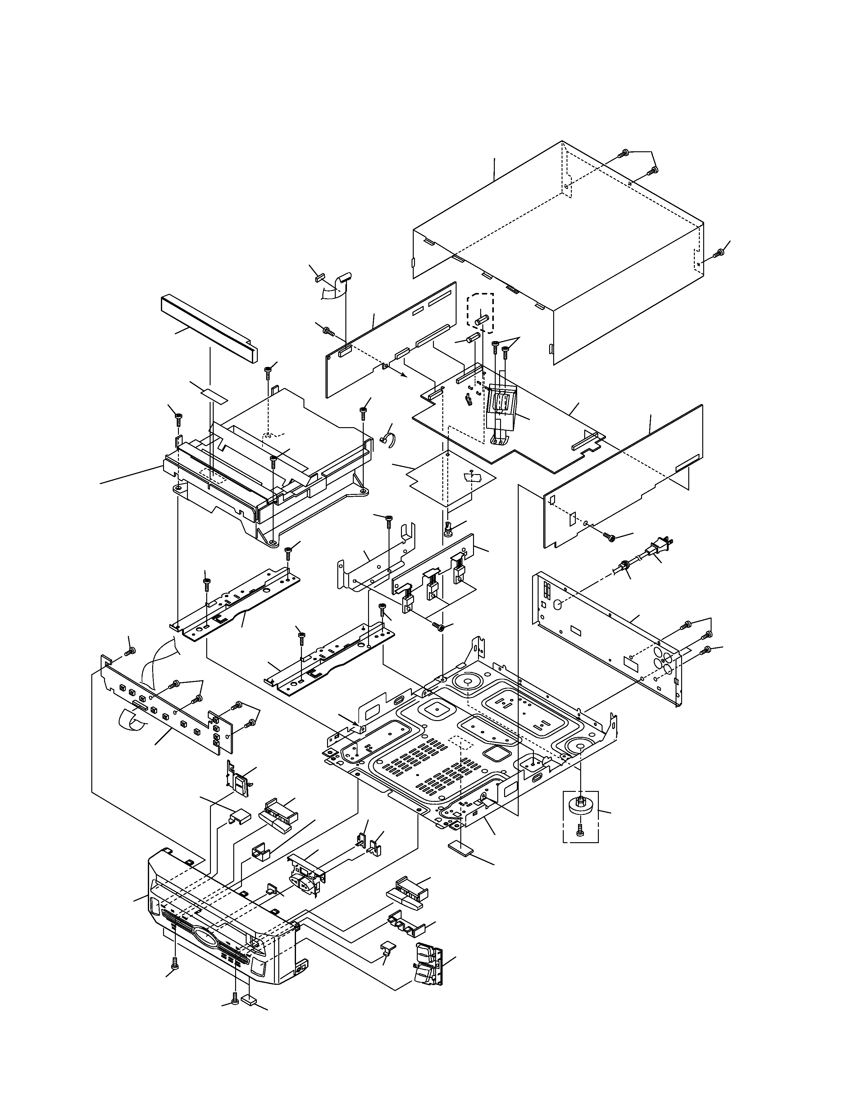
2. EXPLODED VIEWS AND PARTS LIST
NOTES:
· Parts marked by "NSP" are generally unavailable because they are not in our Master Spare Parts List.
· The mark found on some component parts indicates the importance of the safety factor of the part.
Therefore, when replacing, be sure to use parts of identical designation.
· Screws adjacent to mark on the product are used for disassembly.
3
1
4
11
2
12
NV type only
6
5
7 (MY type
only)
8 (MY ,NV
types only)
10 (MY ,NV
types only)
9 (RBD type
only)
Mark No.
Symbol and Description
Part No.
Remarks
MY Type
NV Type
RBD Type
3
Packing Case Y
AHD7788
Not used
Not used
3
Packing Case V
Not used
AHD7789
Not used
3
Packing Case D
Not used
Not used
AHD7786
7
Operating Instructions
ARC7265
Not used
Not used
(Spanish/Portuguese/Dutch/Swedish)
8
Operating Instructions(English/French/German/Italian)
ARE7234
ARE7234
Not used
9
Operating Instructions (English/Chinese/Spanish/Arabic)
Not used
Not used
ARE7235
NSP
10
Warranty Card
ARY7022
ARY7022
Not used
12
Protector V
Not used
AHA7273
Not used
(2) CONTRAST TABLE
CT-IS21/MY, NV and RBD are constructed the same except for the following :
Mark No.
Description
Part No.
8
Operating Instructions
See Contrast table (2)
(English/French/German/Italian)
9
Operating Instructions
See Contrast table (2)
(English/Chinese/Spanish/Arabic)
NSP
10
Warranty Card
See Contrast table (2)
11
Polyethylene Bag
Z21-038
(0.03
× 230 × 340)
12
Protector V
See Contrast table (2)
4
CT-IS21
19
32
1
4
14
15
9
32
33
33
30
7
2
32
25
31
33
33
32
32
32
34
34
13
34
3
24(1/2)
28(3/3)
28(1/3)
27(2/2)
26(1/2)
26(2/2)
22
21
23
27(1/2)
28(2/3)
16
36
20
24(2/2)
12
33
33
29
32
32
18
33
5
17
17
6
Refer to "2.3 and
2.4 DECK MECHA-
NISM UNIT".
33
33
35
A
A
8
RBD
type
only
11
33
33
10
2.2 EXTERIOR
5
CT-IS21
(1) EXTERIOR PARTS LIST
Mark No.
Description
Part No.
Mark No.
Symbol and Description
Part No.
Remarks
MY Type
NV Type
RBD Type
1
AF Assy
AWU7371
AWU7371
AWU7372
4
MAIN Assy
AWU7365
AWU7365
AWU7366
6
Deck Mechanism Unit
AXA7073
AXA7073
AXA7082
8
FU2 Fuse (T315mA)
Not used
Not used
AEK1049
10
AC Power Cord HE
PDG1003
Not used
Not used
10
AC Power Cord HB
Not used
VDG1062
Not used
10
AC Power Cord SD
Not used
Not used
PDG1013
11
Rear Panel Y
ANC7857
Not used
Not used
11
Rear Panel V
Not used
ANC7858
Not used
11
Rear Panel D
Not used
Not used
ANC7853
36
Caution Label
Not used
Not used
ARW7036
(2) CONTRAST TABLE
CT-IS21/MY, NV and RBD are constructed the same except for the following :
Mark No.
Description
Part No.
1
AF Assy
See Contrast table (2)
2
U-COM Assy
AWU7370
3
DISPLAY Assy
AWU7373
4
MAIN Assy
See Contrast table (2)
5
REG. Assy
AWU7369
6
Deck Mechanism Unit
See Contrast table (2)
7
FU1 Fuse (T250mA)
AEK1048
8
FU2 Fuse (T315mA)
See Contrast table (2)
9
T2000 Power Transformer
ATT7051
10
AC Power Cord
See Contrast table (2)
11
Rear Panel
See Contrast table (2)
12
Rubber Sheet
AEB1111
13
Spacer
AEB7133
14
Nylon Rivet
AEC-525
15
Insulation Sheet
AEC7208
NSP
16
Chassis MD, CD
ANA7092
17
Mech Angle T
ANG7213
18
Heat Sink IS
ANH7111
19
Strain Relief
CM-22B
20
Foot Assy
REC-434
21
Function Button A
AAD7510
22
Function Button B
AAD7511
23
Play Button
AAD7534
24
O/C Button
AAD7535
25
Tray Cap
AAK7678
26
Play Lens
AAK7679
27
REC Lens
AAK7680
28
Center Lens
AAK7681
29
Front Panel
AMB7640
30
Bonnet IS
AZN7788
NSP
31
Tray Seal
RRW1162
32
Screw
BBZ30P060FMC
33
Screw
BBZ30P080FZK
34
Screw
BPZ30P080FMC
35
Binder
ZCA-SKB90BK
36
Caution Label
See Contrast table (2)