144MHz FM TRANSCEIVER
TH-K2AT/K2E/K2ET
© 2003-8 PRINTED IN JAPAN
B51-8658-00 (S) 836
SERVICE MANUAL
DISASSEMBLY FOR REPAIR ................................... 2
CIRCUIT DESCRIPTION ............................................ 6
SEMICONDUCTOR DATA ...................................... 14
COMPONENTS DESCRIPTION .............................. 15
PARTS LIST ............................................................. 17
EXPLODED VIEW .................................................... 23
PACKING ................................................................. 25
ADJUSTMENT ........................................................ 27
TERMINAL FUNCTION ........................................... 43
PC BOARD
TX-RX UNIT (X57-674X-XX) (A/3) ................... 44
TX-RX UNIT (X57-674X-XX) (B/3),(C/3) .......... 48
CONTENTS
SCHEMATIC DIAGRAM .......................................... 50
LEVEL DIAGRAM .................................................... 55
BLOCK DIAGRAM ................................................... 56
BC-21 (WALL CHARGER) ....................................... 58
PB-43N (Ni-MH BATTERY PACK) .......................... 58
BT-14 (BATTERY CASE) ......................................... 59
PG-4Y (PROGRAMMING INTERFACE CABLE) ..... 59
MCP-1A (MEMORY CONTROL PROGRAM) ......... 59
SPECIFICATIONS ................................. BACK COVER
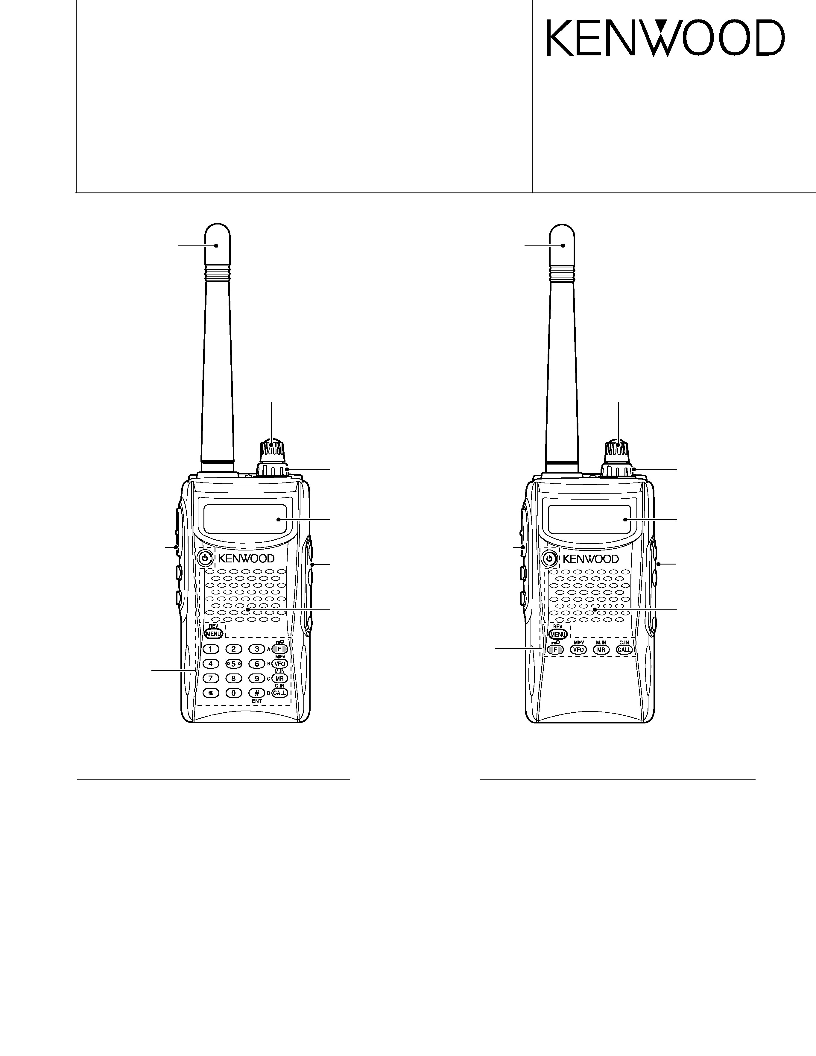
Knob (ENC)
(K29-5159-03)
Knob (VOL)
(K29-5150-03)
Cabinet assy
(16key)
(A02-3819-23)
Helical Antenna
(T90-1018-25)
Key top (16key)
(K29-9272-02)
Front glass
(B10-2746-03)
Knob
(PTT/LAMP/MON)
(K29-9274-03)
Knob (ENC)
(K29-5159-03)
Knob (VOL)
(K29-5150-03)
Cabinet assy
(4key)
(A02-3818-23)
Helical Antenna
(T90-1018-25)
Key top (4key)
(K29-9276-02)
Front glass
(B10-2746-03)
Knob
(PTT/LAMP/MON)
(K29-9274-03)
TH-K2AT/K2ET
TH-K2E
Cap
(SP/MIC/DC IN)
(B09-0675-03)
Cap
(SP/MIC/DC IN)
(B09-0675-03)
TH-K2AT/K2E/K2ET
2
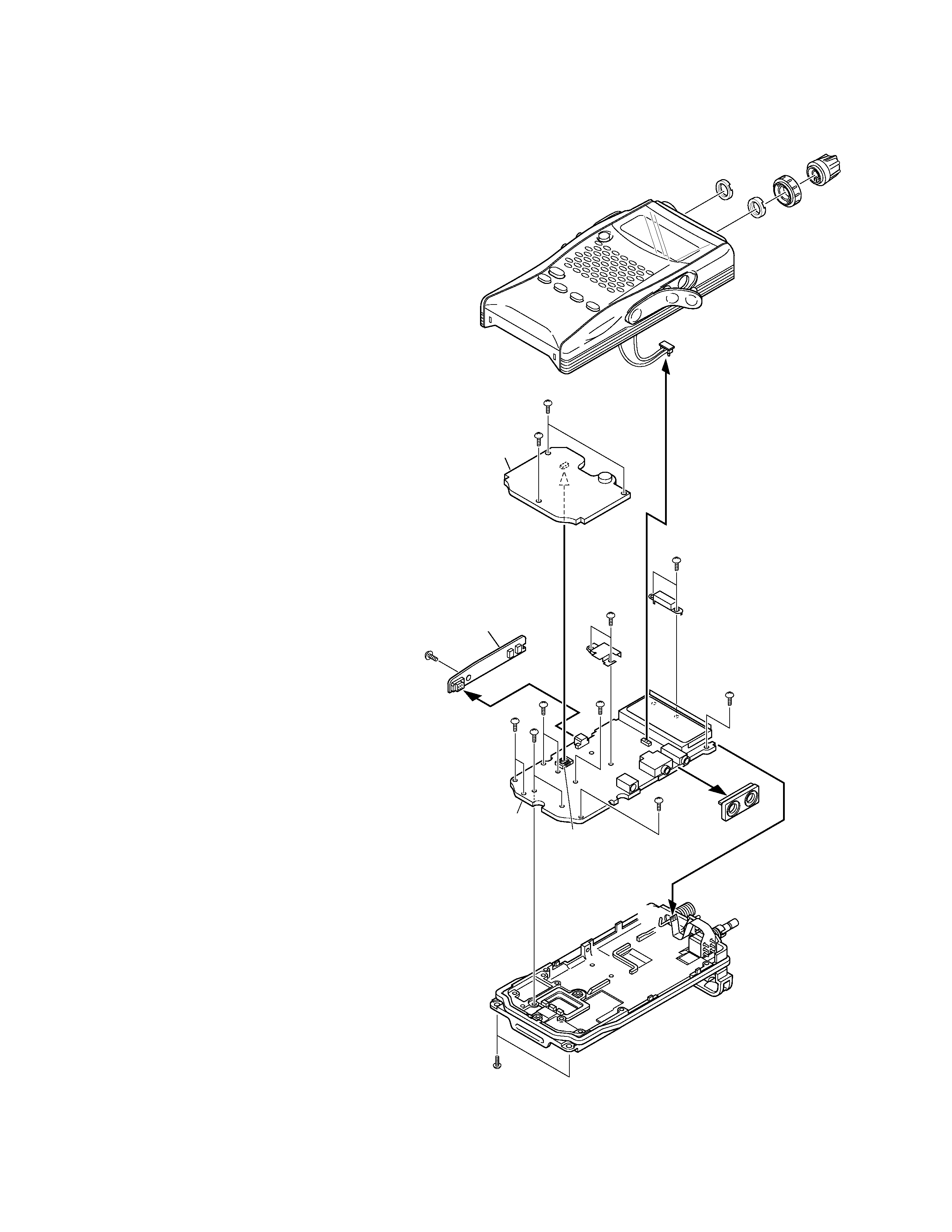
DISASSEMBLY FOR REPAIR
How to remove the case assembly from the
chassis
1. Remove two screws (z) holding the chassis.
2. Pull out two knobs (x) and remove two round nuts (c).
3. Pull out the SP and MIC parts of the cap from jacks (v).
4. Turn the unit over with the bottom of the chassis facing
upwards, and remove the chassis (n) from the case
assembly (b).
5. Remove the speaker lead (m) from the connector (CN2) of
the TX-RX PC board (TX-RX unit A/3).
How to remove the PC board
Numeric key PC board (TX-RX unit B/3)
1. Remove three screws (,) on the numeric key PC board.
2. Lift the numeric key PC board and remove it from the
connector (CN9) of the TX-RX PC board (.).
PTT PC board (TX-RX unit C/3)
3. Remove one screw on the PTT PC board (/).
4. Pull the PTT PC board to the left and remove it from the
connector (CN6) of the TX-RX PC board (TX-RX unit A/3)
().
TX-RX PC board (TX-RX unit A/3)
5. Remove the SP/MIC jack cover ().
6. Remove two screws (ç) holding the shield
cover (antenna terminal section).
7. Remove two screws () holding the shield
cover (final amplifier section).
8. Remove eight screws () on the TX-RX PC
board.
9. Absorb solder from the antenna terminal (~)
with a solder absorber.
Note: Do not melt the shadow plate (µ) when
moving the tip of the solder absorber close
to the antenna terminal.
10. Remove the TX-RX PC board from the chassis, then remove
the encoder volume FPC () from the flat cable connector
of the TX-RX PC board.
CN2
CN9
CN6
x
x
c
c
v
m
b
,
,
.
ç
µ
/
~
n
z
TX-RX unit (B/3)
TX-RX unit (C/3)
TX-RX unit (A/3)
TH-K2AT/K2E/K2ET
3
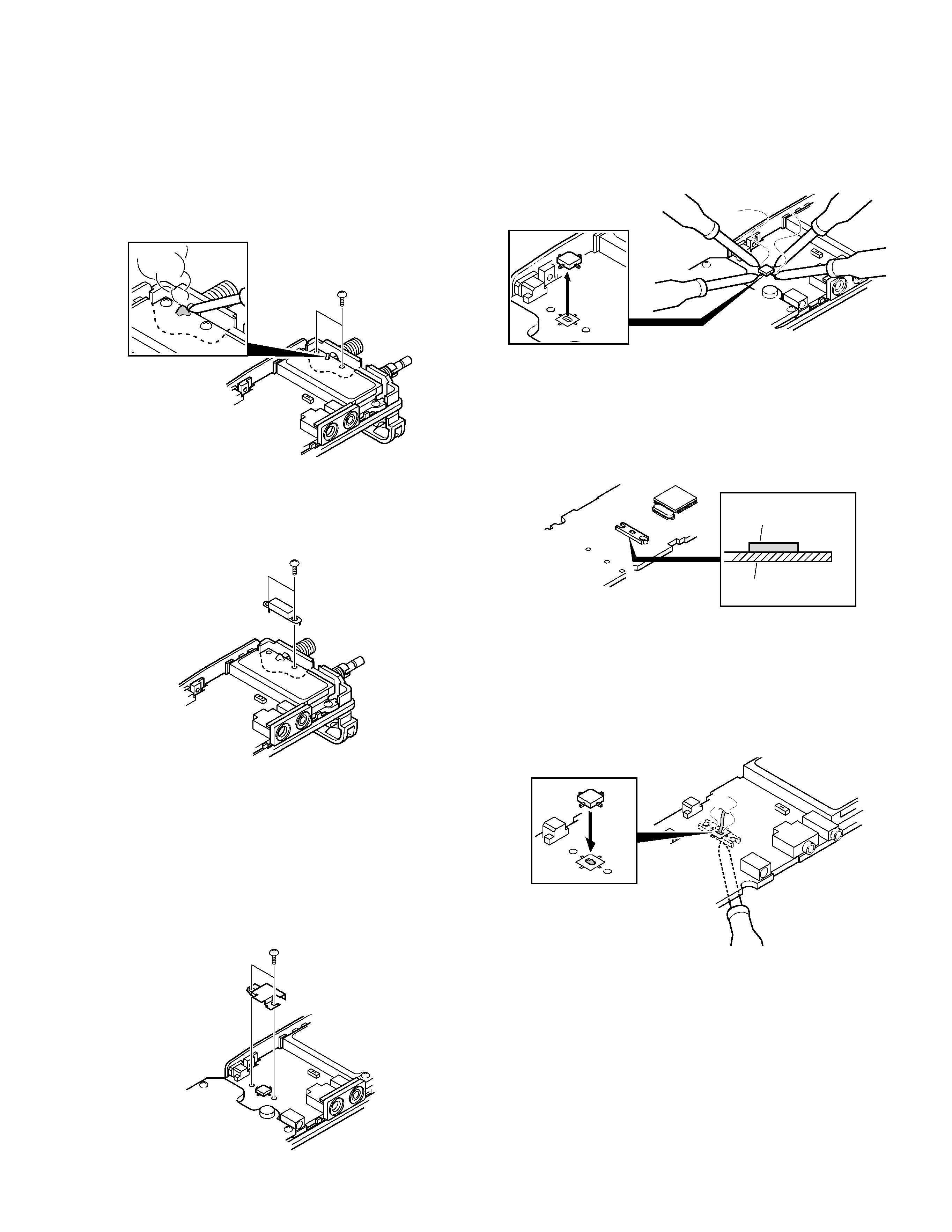
DISASSEMBLY FOR REPAIR
Soldering the antenna terminal
1. With the shield cover removed from the antenna terminal
section, install two screws on the PC board and bring the
PC board into contact with the chassis (z).
2. Solder the antenna terminal with a soldering iron (x).
3. Remove the two screws installed in step 1 above, and install
the two screws again on the PC board together with the
shield cover (c).
Replacing the final FET (Q12)
1. Remove the two screws holding the shield cover of the
final FET section (z).
2. Remove solder from the shield cover completely with a
solder absorber. (E and E3 types only)
3. Remove the shield cover (x).
z
x
c
z
x
4. Apply the tips of soldering irons to all the four pins of the final
FET at the same time (c), heat them sufficiently, and remove
the final FET (v). (Two persons should be required to do this.)
5. Remove all PC boards from the chassis.
6. Confirm that there is no space between the radiation plate
installed on the foil side of the TX-RX PC board (TX-RX unit
A/3) and the PC board (b). If there is any space between
the radiation plate and PC board, eliminate it by applying
the tip of the soldering iron to the radiation plate.
7. Apply the tip of the soldering iron to the installation side of the
radiation plate of the TX-RX PC board, put a little amount of
solder to the radiation plate that is seen through a square hole
in the final FET installation section and melt the solder (n).
8. When the solder in step 7 is melted, place the final FET on
the PC board by aligning it with the silk of the final FET
installation section of the PC board (m).
9. Release the soldering iron and confirm that the final FET
and radiation plate have been soldered.
10. Solder the four pins of the final FET with the soldering iron.
11. Install all the PC boards.
12. Reinstall the shield cover removed in step 3 above in its
original position and install two screws.
13. Solder the shield cover to the PC board. (E and E3 types
only)
14. Install the chassis on the case assembly and assemble them.
15. Readjust transmission power.
Note: Since the FET is sensitive to static electricity, always
wear a grounding band. Use a highly insulated ceramic
heater solder iron.
Radiation plate
TX-RX PC board
b
c
v
m
n
TH-K2AT/K2E/K2ET
4
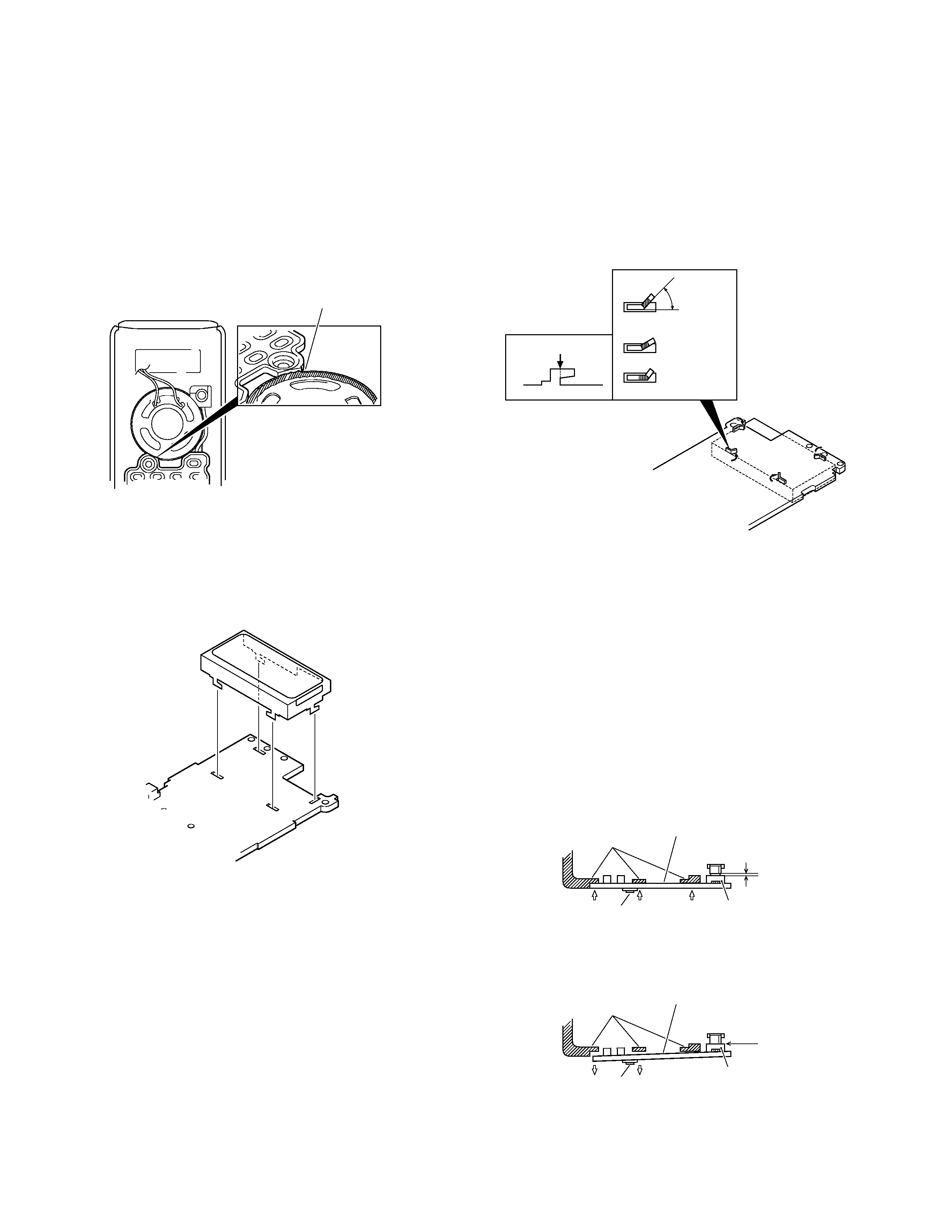
DISASSEMBLY FOR REPAIR
Special care and attention required for assembly
1. Gluing to the key top (MIC element section)
You must also glue on the speaker storage area and heap
the glue up until wealthy glued on the speaker storage area
and the key top for waterproofing the MIC element side of
the key top. (Fig. 1)
Fig. 1
2. Bending the LCD hardware fixture (J21-8456-03) tabs
(1) Insert the tabs of the LCD hardware fixture into four holes
in the LCD installing position of the TX-RX PCB (TX-RX unit
A/3). (Fig. 2)
Heap the glue up until wealthy glued on the speaker
storage area and the key top (MIC element section).
Fig. 2
(2) By pressing the LCD hardware fixture from the component
side of the TX-RX PCB, you must bent all 4 tabs of the LCD
hardware fixture being visible from the foil side until the
bases of each tabs are folded at least 45 degrees (Fig. 3). If
the bending angle of the tabs of the LCD hardware fixture
is less than 45 degrees, a display error may occur.
Bending position
NG
NG
Min 45
degrees
3. PTT PCB (TX-RX unit C/3) installation procedure
Installing the PTT PCB on the TX-RX PCB and chassis are
as follows:
(1) Insert the PTT PCB connector (CN7) into the TX-RX PCB
connector (CN6) lightly.
(2) Push three parts of the PTT PCB to contact tightly with the
chassis. There may be a small gap between the connectors.
(Fig. 4)
Note: A double-side adhesive tape (J99-0376-04) is used
behind the PTT switch. When reassembling the PTT
PCB to the chassis, press the PTT PCB (under the PTT
switch) so that the tape hold the PCB and chassis
securely.
Fig. 3
CN6
Chassis
PTT switch
PTT PCB (C/3)
OK
A bit
clearance
No
clearance
NG
CN6
CN7
CN7
Chassis
PTT PCB (C/3)
PTT switch
Fig. 4
Push three parts of the PTT PCB
to contact tightly with the chassis.
(3) Tighten one screw in the PTT PCB.
TH-K2AT/K2E/K2ET
5
DISASSEMBLY FOR REPAIR
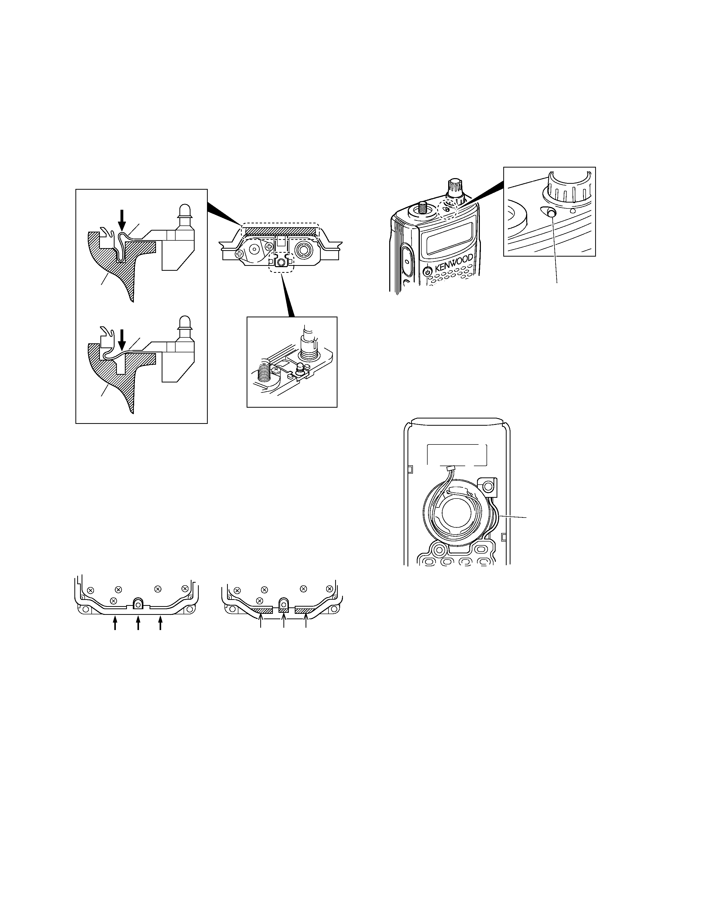
4. Packing (G53-1572-02) TX/BUSY lamp installation
procedure
(1) To assure waterproofing, install the packing in the chassis
groove as shown in Fig. 5. (z)
(2)Install the packing TX/BUSY lamp section on the chassis.
(x)
z
x
OK
Packing
NG
Packing
Chassis
Chassis
5. Packing (G53-1572-02) bottom installation procedure
(1) Before installing the numeric key PCB (TX-RX unit B/3) on
the chassis, push three parts of the packing to contact tightly
with the chassis as shown in Fig. 6. If the packing is not in
contact with the chassis, there may be a gap between the
transceiver bottom case assembly and the battery, and
water may enter through the gap.
Fig. 5
OK
NG
Push three parts of the packing to
contact tightly with the chassis.
Clearance NG
Fig. 6
6. Cautions for installing the chassis on the case assembly
(1) Verify that the packing (G53-1572-02) TX/BUSY lamp section
is has been past through the hole in the illumination guide
section on the top of the case assembly. (Fig. 7)
LAMP
LOW
PTT
Fig. 7
(2)Align the speaker lead as shown fig.8. Do not place the
leads over the key top section, LCD section or SP/MIC/DC
IN cap section.
Do not fix this part of the
key top to the rib of the
case assembly.
7. Cautions for installing the key top on the case assembly
(1) Install the key top keypad section and the power switch
section on the rib of the case assembly.
(2) Do not fix the part between the key top keypad section and
the power switch section to the rib of the case assembly,
but install it as shown in Fig. 8.
The packing TX/BUSY lamp section is has
been past through the hole in the illumination
guide section on the top of the case assembly.
Fig. 8