
B60-3069-00 CS (K, P, Y)
98/12 11 10 9 8 7 6 5 4 3 2 1 97/12 11 10 9 8 7 6 5 4 3 2 1
AUDIO VIDEO SURROUND RECEIVER
KR-897
KR-797
INSTRUCTION MANUAL
KENWOOD CORPORATION
This manual contains instructions for two models. Model availability and features
(functions) may differ depending on country and sales area.
Model KR-897 is not available in except for U.S.A. and Canada.
MC
07.6.11, 5:05 PM
1
KR-897/KR-797 (En)
2
Units are designed for operation as follows.
Europe and U.K. .............................................. AC 230 V only
China and Russia ............................................ AC 220 V only
*Other countries ..................... AC 110-120/220-240 V switchable
U.S.A. and Canada ........................................... AC120 V only
Australia ....................................................... AC 240 V only
WARNING : TO PREVENT FIRE OR ELECTRIC SHOCK, DO NOT EXPOSE THIS
APPLIANCE TO RAIN OR MOISTURE.
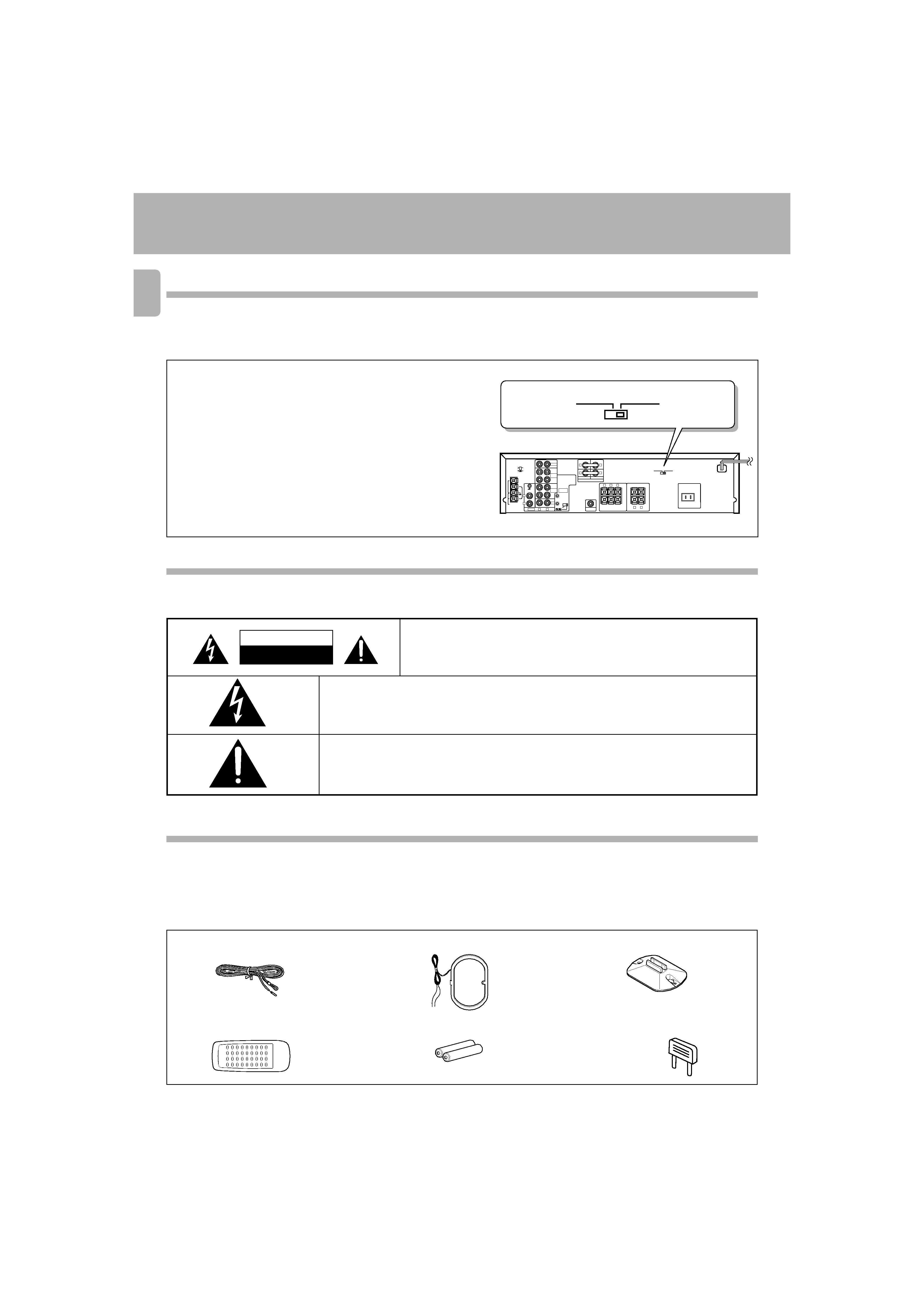
FM indoor antenna (1)
Remote control unit (1)
AC voltage selector switch
Unpack the unit carefully and make sure that all accessories are put aside so they will not be lost. Examine the unit for any possibility of shipping damage.
If your unit is damaged or fails to operate, notify your dealer immediately. If your unit was shipped to you directly, notify the shipping company without delay.
Only the consignee (the person or company receiving the unit) can file a claim against the carrier for shipping damage. We recommend that you retain the
original carton and packing materials for use should you transport or ship the unit in the future.
Unpacking
Before applying power
Safety precautions
CAUTION
RISK OF ELECTRIC SHOCK
DO NOT OPEN
Note:
Our warranty does not cover damage caused by excessive line voltage
due to improper setting of the AC voltage selector switch.
Before applying power
Accessories
THE LIGHTNING FLASH WITH ARROWHEAD SYMBOL, WITHIN AN EQUILATERAL TRIANGLE, IS IN-
TENDED TO ALERT THE USER TO THE PRESENCE OF UNINSULATED "DANGEROUS VOLTAGE" WITHIN
THE PRODUCT'S ENCLOSURE THAT MAY BE OF SUFFICIENT MAGNITUDE TO CONSTITUTE A RISK OF
ELECTRIC SHOCK TO PERSONS.
THE EXCLAMATION POINT WITHIN AN EQUILATERAL TRIANGLE IS INTENDED TO ALERT THE USER TO
THE PRESENCE OF IMPORTANT OPERATING AND MAINTENANCE (SERVICING) INSTRUCTIONS IN THE
LITERATURE ACCOMPANYING THE APPLIANCE.
CAUTION: TO REDUCE THE RISK OF ELECTRIC SHOCK, DO NOT REMOVE COVER
(OR BACK). NO USER-SERVICEABLE PARTS INSIDE, REFER SERVICING TO QUALI-
FIED SERVICE PERSONNEL.
*AC voltage selection
The AC voltage selector switch on the rear panel is set to the voltage
that prevails in the area to which the unit is shipped. Before connecting
the power cord to your AC outlet, make sure that the setting position
of this switch matches your line voltage. If not, it must be set to your
voltage in accordance with the following direction.
Move switch lever to match your line voltage
with a small screwdriver or other pointed tool.
REC OUT
PLAY IN
VIDEO 1
/TAPE 1
PLAY IN
TAPE 2
MONITOR
VIDEO 2
SUBWOOFER
PRE OUT
PLAY
IN
+
-
FRONT SPEAKERS
( 8
-16)
SURROUND
SPEAKERS
( 4
-8)
CENTER
SPEAKER
( 8
-16)
+
-
SYSTEM
CONTROL
SWITCHED
AC 110-120V AC 220-240V
50/60Hz
FM
75
GND
AM
ANTENNA
CD
PHONO
L
R
R
L
R
L
R
L
C
AUDIO
FM
300
REC OUT
DE
-
EMPHASIS
CHANNEL
SPACE
50
s
AM 9kHz
FM 50kHz
75
s
AM 10kHz
FM 100kHz
ADAPTOR
L
R
L
R
OUT
IN
AC 220-
240V
AC 110-
120V
AC 220-
240V
AC 110-
120V
3 Caution : Read this section carefully to ensure safe operation.
3 Caution : Read this section carefully to ensure safe operation.
Batteries (R6/AA) (2)
AM loop antenna (1)
Loop antenna stand (1)
Shorting pins (2)
(KR-797 only)
07.6.11, 5:05 PM
2

KR-897/KR-797 (En)
3
The surround system reproduces video software programs carrying the
mark with similar acoustic effects to movie
theaters.
The DOLBY PRO LOGIC mode controls the audio signals of the Front Left/Right, Center and Rear surround channels using the built-in
directivity enhancer circuit to reproduce the feeling of sound motions very realistically.
The DOLBY 3 STEREO mode can reproduce the motions of sound even when only the front and center speakers are used, by providing proper
acoustic position using the directivity enhancer circuit.
The SRS (Sound Retrieval System) is an innovative system simulating a 3-dimensional sound space, which features clearly improved
feelings of depth, sound field extension and acoustic image positioning as well as a widened listening area.
Special features
DOLBY PRO LOGIC & DOLBY 3 STEREO
SRS 3D Stereo
Contents
Caution : Read the pages marked
3 carefully to
ensure safe operation.
Before applying power ............................................................................................................................................................................................. 2
3 Before applying power......................................................................................................................................... 2
3 Safety precautions ............................................................................................................................................... 2
Special features ......................................................................................................................................................................................................... 3
System connection ..................................................................................................................................................................................................... 4
Connections of Audio and Video components (KR-897) ...................................................................................... 4
Connections of Audio and Video components (KR-797) ...................................................................................... 5
About the system control connections ................................................................................................................. 6
Connection of speakers (KR-897) ........................................................................................................................ 7
Connection of speakers (KR-797) ........................................................................................................................ 8
Connection of antenna ......................................................................................................................................... 9
FM DE-EMPHASIS / CHANNEL SPACE switch .................................................................................................. 10
Controls and indicators ........................................................................................................................................................................................... 11
Operation of remote control unit ........................................................................................................................................................................... 12
Playing music ............................................................................................................................................................................................................ 14
Sound adjustment functions .................................................................................................................................................................................. 15
Recordin ..................................................................................................................................................................................................................... 18
Broadcast receptiong .............................................................................................................................................................................................. 19
Receiving broadcast stations ............................................................................................................................ 19
Receiving radio stations by specifying its frequency ......................................................................................... 20
Storing radio stations in memory (Station preset) ............................................................................................. 21
Receiving a preset station ................................................................................................................................. 21
Receiving all preset stations in order (P. CALL) .................................................................................................. 21
Presence play ........................................................................................................................................................................................................... 23
Adjustments for surround play .......................................................................................................................... 24
Surround play ..................................................................................................................................................... 26
SRS 3D Stereo (Sound Retrieval System) .......................................................................................................... 27
In case of difficulty .................................................................................................................................................................................................. 28
3 Specifications ........................................................................................................................................................................................................... 30
07.6.11, 5:05 PM
3
KR-897/KR-797 (En)
4
PRE OUT
CENTER
L
R
SURROUND
FRONT
FRONT
REC OUT
PLAY IN
VIDEO 1
/TAPE 1
PLAY IN
TAPE 2
MONITOR
VIDEO 2
SUBWOOFER
PRE OUT
PLAY
IN
+
-
FRONT SPEAKERS
( 8
-16)
SWITCHED
FM
75
GND
AM
CD
PHONO
L
R
R
L
R
L
AUDIO
FM
300
REC OUT
SYSTEM
CONTROL
ANTENNA
PGM FILE
(
)
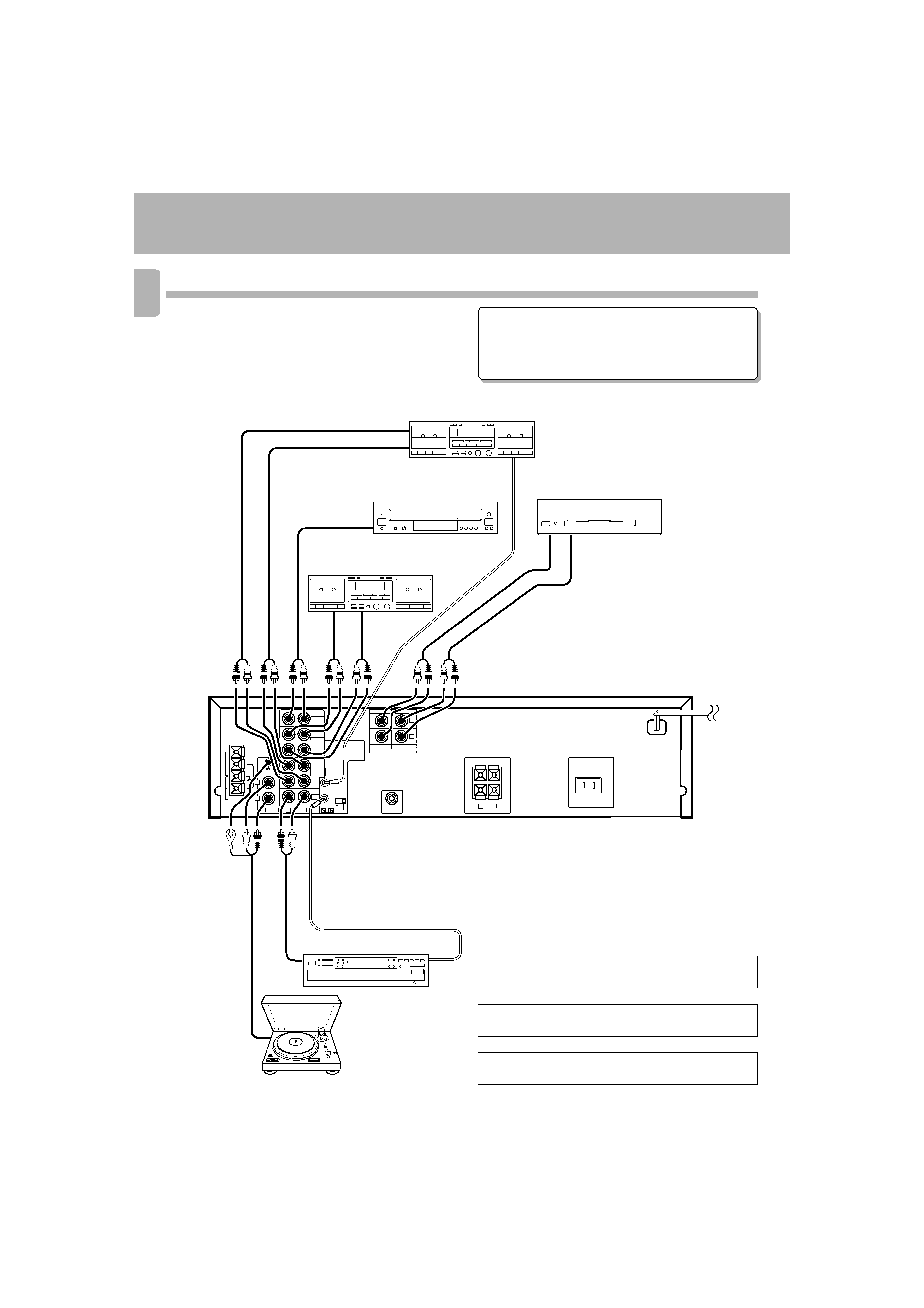
System connection
Make connection as shown below.
When connecting the related system components, refer
also to the instruction manuals of the related compo-
nents.
3 Do not plug in the power lead until all connections are
completed.
Connections of Audio and Video components (KR-897)
To wall
AC outlet
Turntable
Malfunction of microcomputer
If operation is not possible or erroneous display appears even
though all connections have been made properly, reset the micro-
computer referring to "In case of difficulty".
·
Video deck 2 or DVD/LD player
IN
OUT
*2 Do not connect system control cord to the cassette
deck connected to the TAPE 2 MONITOR jacks.
*1 The system control cord should be connected when a
KENWOOD audio component system is connected.
*3 The KX-W797 and KM-897 are not marketed in other
areas than the USA and Canada.
Audio OUT
REC
IN
PLAY
OUT
Multipul CD player
DP-R797
÷ Do not connect up a power source which is
larger than that indicated on the socket at the
rear of the unit.
System control cord
Audio
Cassette deck 1, MD recorder
or VCR 1
*1 System
control cord
Cassette deck
KX-W597/KX-W797*3
Power amplifier
KM-897*3
*2 Cassette deck 2
07.6.11, 5:05 PM
4
KR-897/KR-797 (En)
5
L
R
REC OUT
PLAY IN
VIDEO 1
/TAPE 1
PLAY IN
TAPE 2
MONITOR
VIDEO 2
SUBWOOFER
PRE OUT
PLAY
IN
+
-
FRONT SPEAKERS
( 8
-16)
SWITCHED
FM
75
GND
AM
CD
PHONO
L
R
R
L
R
L
AUDIO
FM
300
REC OUT
SYSTEM
CONTROL
ANTENNA
SURROUND
SPEAKERS
( 4
-8)
CENTER
SPEAKER
( 8
-16)
+
-
R
L
C
ADAPTOR
L
R
OUT
IN
PGM FILE
(
)
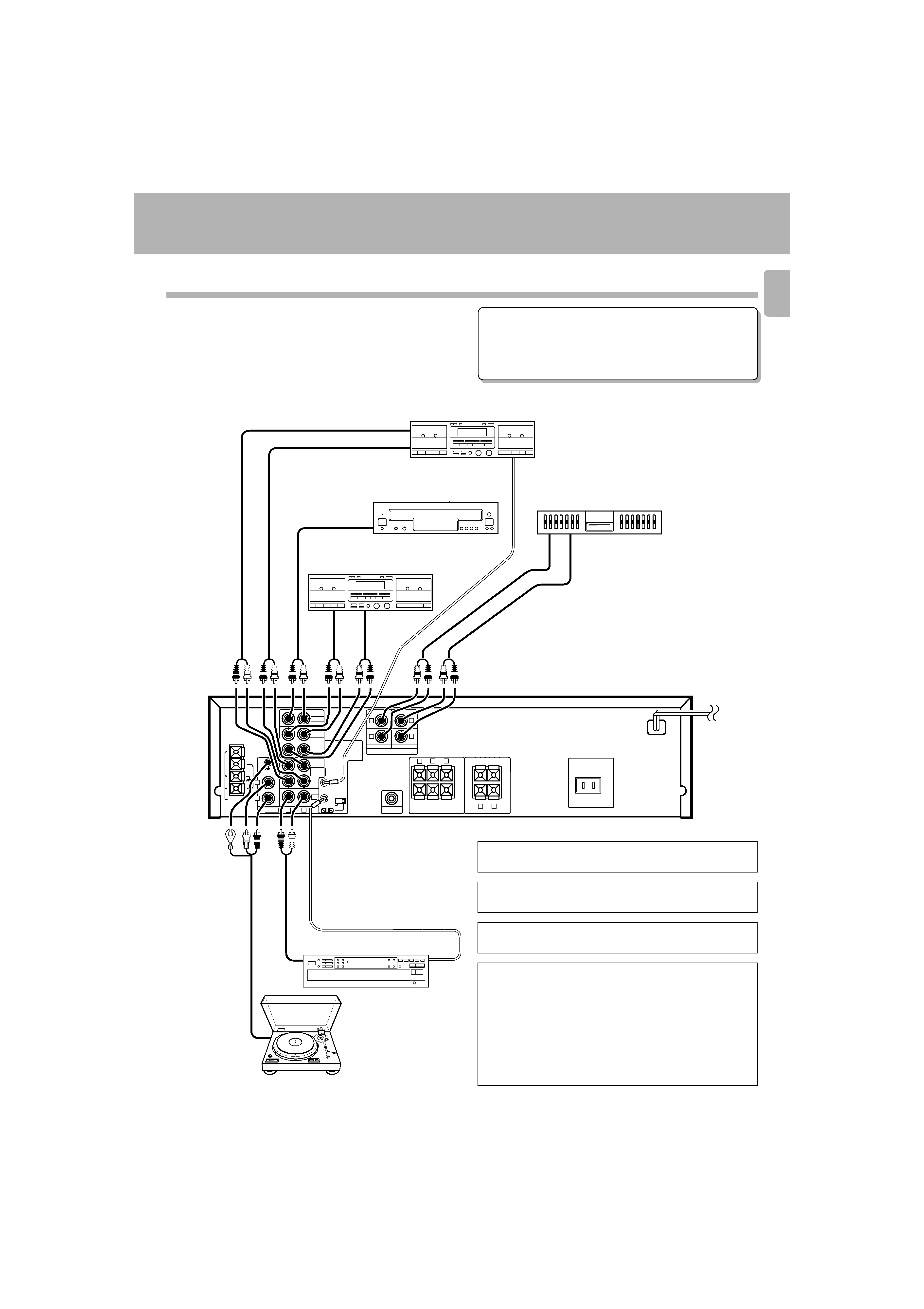
Make connection as shown below.
When connecting the related system components, refer
also to the instruction manuals of the related compo-
nents.
3 Do not plug in the power lead until all connections are
completed.
Connections of Audio and Video components (KR-797)
To wall
AC outlet
Turntable
Malfunction of microcomputer
If operation is not possible or erroneous display appears even
though all connections have been made properly, reset the micro-
computer referring to "In case of difficulty".
·
Multipul CD player
DP-R797
*1 System
control cord
OUT
IN
REC
IN
PLAY
OUT
Audio OUT
IN
OUT
Audio
Video deck 1, cassette deck 1
or MD recorder
System control cord
Graphic
equalizer
KE-597
cassette deck
KX-W597/KX-W797*1
Caution regarding placement
(Except for U.S.A. and Canada)
To maintain proper ventilation, be sure to leave a space around the
unit (from the largest outer dimensions including projections)
equal to, or greater than, shown below.
Left and right panels : 10 cm
Rear panel
: 10 cm
Top panel
: 50 cm
*3 The KX-W797 and KM-897 are not marketed in other
areas than the USA and Canada.
*2 Do not connect system control cord to the cassette
deck connected to the TAPE 2 MONITOR jacks.
*1 The system control cord should be connected when a
KENWOOD audio component system is connected.
System connection
Video deck 2 or DVD/LD player
÷ Do not connect up a
power source which is
larger than that indi-
cated on the socket at
the rear of the unit.
*2 Cassette deck 2
07.6.11, 5:05 PM
5