
KAC-648S
4-CHANNEL POWER AMPLIFIER
Page 2-11
INSTRUCTION MANUAL
AMPLIFICATEUR DE PUISSANCE 4 CANAUX
Page 12-21
MODE D'EMPLOI
AMPLIFICADOR DE POTENCIA DE 4 CANALES
Page 22-31
MANUAL DE INSTRUCCIONES
© PRINTED IN MEXICO B64-1363-00 (KM)
Take the time to read through this instruction manual.
Familiarity with installation and operation procedures will help
you obtain the best performance from your new power amplifier.
For your records
Record the serial number, found on the back of the unit, in the spaces
designated on the warranty card, and in the space provided below.
Refer to the model and serial numbers whenever you call upon your
KENWOOD dealer for information or service on the product.
Model KAC-648S Serial number
2 English
Safety precautions
Protection function
This unit is equipped with a protection function for protecting this unit and your speakers
from various accidents or problems that can occur.
When the protection function is triggered, the Power indicator goes off and the amplifier
stops operating.
s Power indicator:
When the power is turned on, the Power indicator lights.
If the Power indicator does not light when the power is turned on, the
protection function may be activated. Check whether there is any
indication of trouble.
s The protection function activates in the following
situations:
· When a speaker wire may be short-circuited.
· When a speaker output contacts ground.
· When the temperature of internal parts exceeds 120°C (248°F).
· When a ground wire of the center unit (cassette receiver, CD receiver,
etc.) or this unit is not connected to a metal part serving as an
electrical ground passing electricity to the battery's negative
-
terminal.
Power indicator
To prevent injury or fire, take the following
precautions:
· When extending the ignition, battery, or
ground wires, make sure to use automotive-
grade wires or other wires with a 3mm2
(AWG12) or more to prevent wire
deterioration and damage to the wire coating.
· To prevent a short circuit, never put or leave
any metallic objects (such as coins or metal
tools) inside the unit.
· If the unit starts to emit smoke or strange
smells, turn off the power immediately and
consult your Kenwood dealer.
· Do not touch the unit during use because the
surface of the unit becomes hot and may
cause burns if touched.
To prevent damage to the machine, take the
following precautions:
· Be sure the unit is connected to a 12V DC
power supply with a negative ground
connection.
· Do not open the top or bottom covers of the
unit.
· Do not install the unit in a spot exposed to
direct sunlight or excessive heat or humidity.
Also avoid places with too much dust or the
possibility of water splashing.
· When replacing a fuse, only use a new one
with the prescribed rating. Using a fuse with
the wrong rating may cause your unit to
malfunction.
· To prevent a short circuit when replacing a
fuse, first disconnect the wiring harness.
· If you experience problems during
installation, consult your Kenwood dealer.
· If the unit does not seem to be working right,
consult your Kenwood dealer.
Cleaning the unit
If the front panel gets dirty, turn off the power
and wipe the panel with a dry silicon cloth or
soft cloth.
Do not wipe the panel with a hard cloth or a
cloth dampened by volatile solvents such as
paint thinner and alcohol. They can scratch the
surface of the panel and/or cause the indicator
letters to peel off.
FCC WARNING
This equipment may generate or use radio
frequency energy. Changes or modifications
to this equipment may cause harmful
interference unless the modifications are
expressly approved in the instruction manual.
The user could lose the authority to operate
this equipment if an unauthorized change or
modification is made.
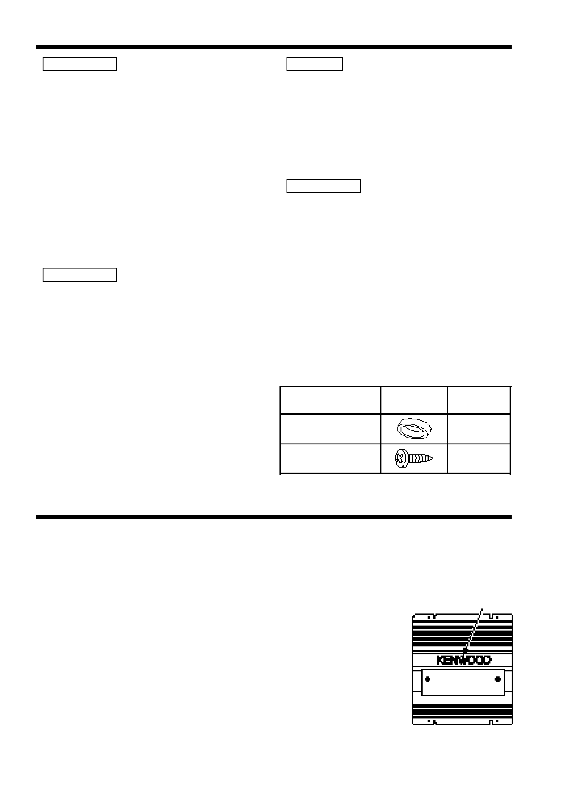
Accessories
CAUTION
NOTE
CAUTION
WARNING
Part name
Number of
Items
External
View
Terminal cover
(Power terminal)
1
Self-tapping screws
(ø4
× 16 mm)
4
English
3
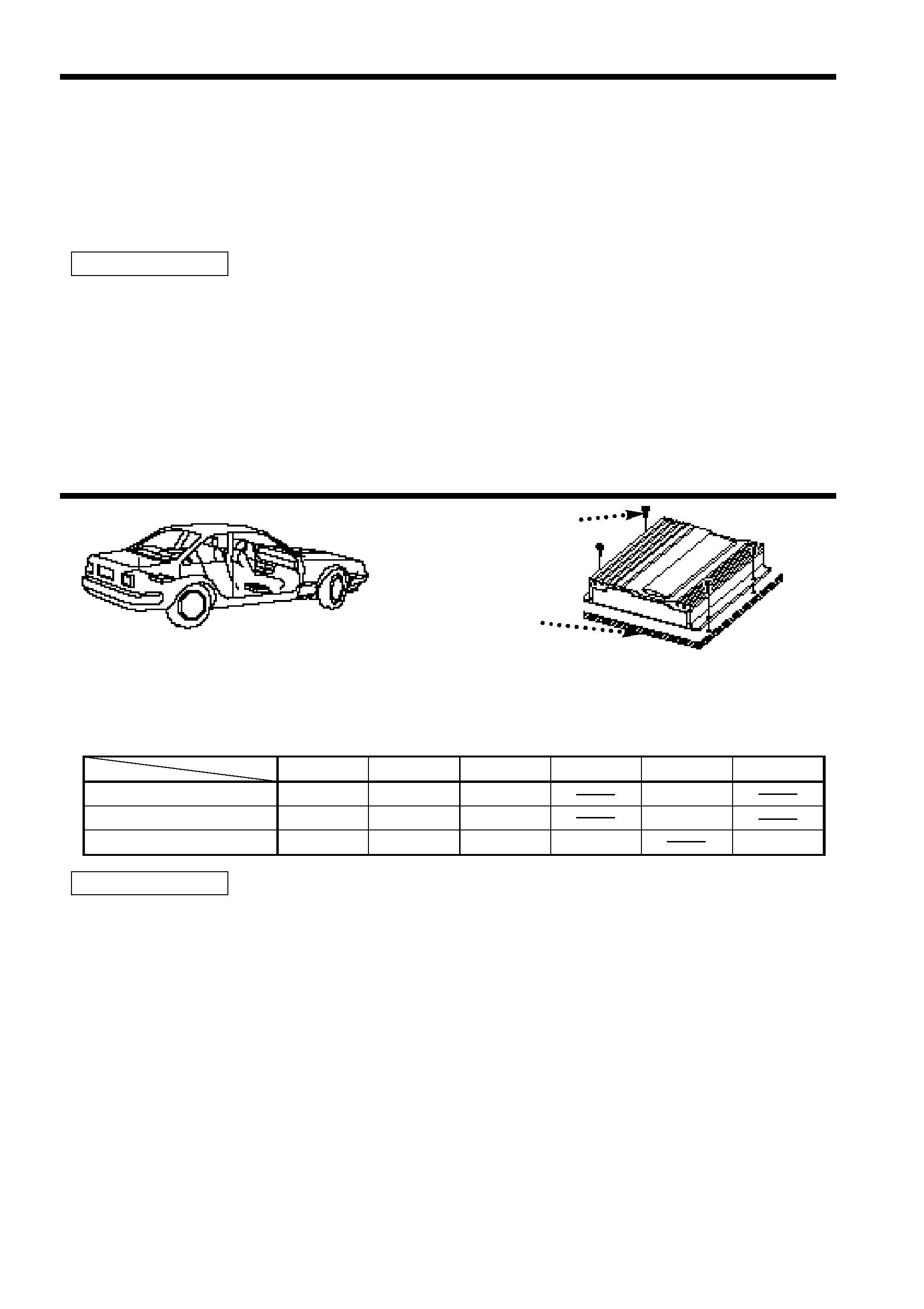
Installation procedure
1. Remove the ignition key and disconnect the negative
- terminal of the battery to prevent short
circuits.
2. Set the unit according to the intended usage.
3. Connect the input and output cables of the units.
4. Connect the speaker wires.
5. Connect the power wire, power control wire and grounding wire following this order.
6. Install the unit in the car.
7. Connect the negative
- terminal of the battery.
· Be sure to turn the power off before changing the setting of any switch.
· If the fuse blows, check wires for shorts, then replace the fuse with one of the same rating.
· Check that no unconnected wires or connectors are touching the car body. Do not remove caps
from unconnected wires or connectors to prevent short circuits.
· Connect the speaker wires to appropriate speaker connectors separately. Sharing the negative
wire of the speaker or grounding speaker wires to the metal body of the car can cause this unit
to fail.
· After installation, check that the brake lamps, winkers, and wipers work properly.
CAUTION
Installation
· Since the power amplifier has no parts which require operation, it can be installed at a position
away from the driver's seat without any hindrances.
As generally accepted positions for its installation, places such as inside the trunk, etc. can be
considered.
· Use the extension cables. (Optional.)
· Do not install the unit under the carpet. Otherwise heat build-up occurs and the unit may be
damaged.
· Install this unit in a location which allows heat to easily dissipate.
Once installed, do not place any object on top of the unit.
· The surface temperature of the amplifier will become hot during use. Install the amplifier in a
place where people, resins, and other substances that are sensitive to heat will not come into
contact with it.
· When making a hole under a seat, inside the trunk, or somewhere else in the vehicle, check
that there is nothing hazardous on the opposite side such as a gasoline tank, brake pipe, or
wiring harness, and be careful not to cause scratches or other damage.
· Do not install near the dashboard, rear tray, or air bag safety parts.
· The installation to the vehicle should securely fasten the unit to a place in which it will not
obstruct driving. If the unit comes off due to a shock and hits a person or safety part, it may
cause injury or an accident.
· After installing the unit, check to make sure that electrical equipment such as the brake lamps,
turn signal lamps and windshield wipers operate normally.
CAUTION
Installation board, etc.
(thickness : 15 mm or more)
Self-tapping screw
(ø4
× 16 mm)
CA-2SL
CA-12SL
CA-22SL
CA-52SL
RCA cable
CA-3WL
CA-13WL
CA-23WL
CA-53WL
RCA cable (ø7mm)
CA-5W
CA-15W
CA-25W
CA-45W
CA-65W
RCA cable (ø12mm)
0.5m
1m
2m
4m
5m
6m
Type
Length
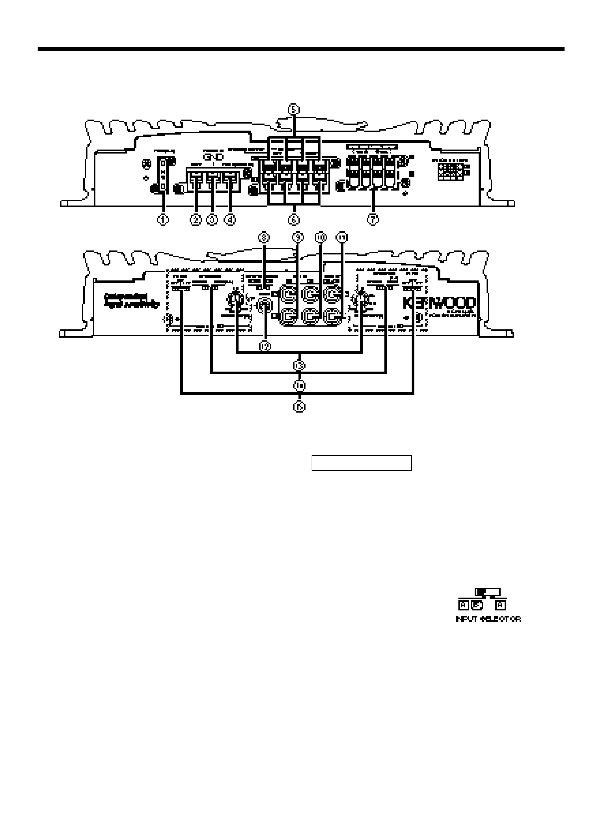
1 Fuse (25 A × 1)
2 Battery terminal
3 Ground terminal
4 Power control (REMOTE) terminal
5 Amplifier A speaker output
terminals
6 Amplifier B speaker output
terminals
y SPEAKER OUTPUT terminals
· Stereo Connections:
When you wish to use the unit as a stereo
amplifier, stereo connections are used.
The speakers to be connected should have
an impedance of 2
or greater. When
multiple speakers are to be connected,
ensure that the combined impedance is 2
or greater for each channel.
· Bridged Connections:
When you wish to use the unit as a high-
output monaural amplifier, bridged
connections are used. (Make connections
to the LEFT channel (+) and the RIGHT
channel () SPEAKER OUTPUT terminals.)
The speakers to be connected should
have an impedance of 4
or greater.
When multiple speakers are to be
connected, ensure that the combined
impedance is 4
or greater.
The rated input of the speakers should be
no less than the maximum output of the
amplifier. Otherwise malfunction may
result.
7 Speaker level input terminals
8 INPUT SELECTOR switch
This switch selects the input method of the
signals to be amplified by amplifiers A and
B.
· A B position:
Amplifies both of the signals input to
amplifiers A and B.
· A position:
Amplifies only signal input amplifier A with
both amplifiers A and B.
9 Amplifier A LINE IN terminal
0 Amplifier B LINE IN terminal
CAUTION
4 English
Controls
This is a 4 channel amplifier including 2 stereo amplifiers in a body. One amplifier is referred to
as amplifier A and the other is amplifier B. This unit is compatible with a large variety of
systems by combining the switches and functions described in the following.
Amplifier A
Amplifier B
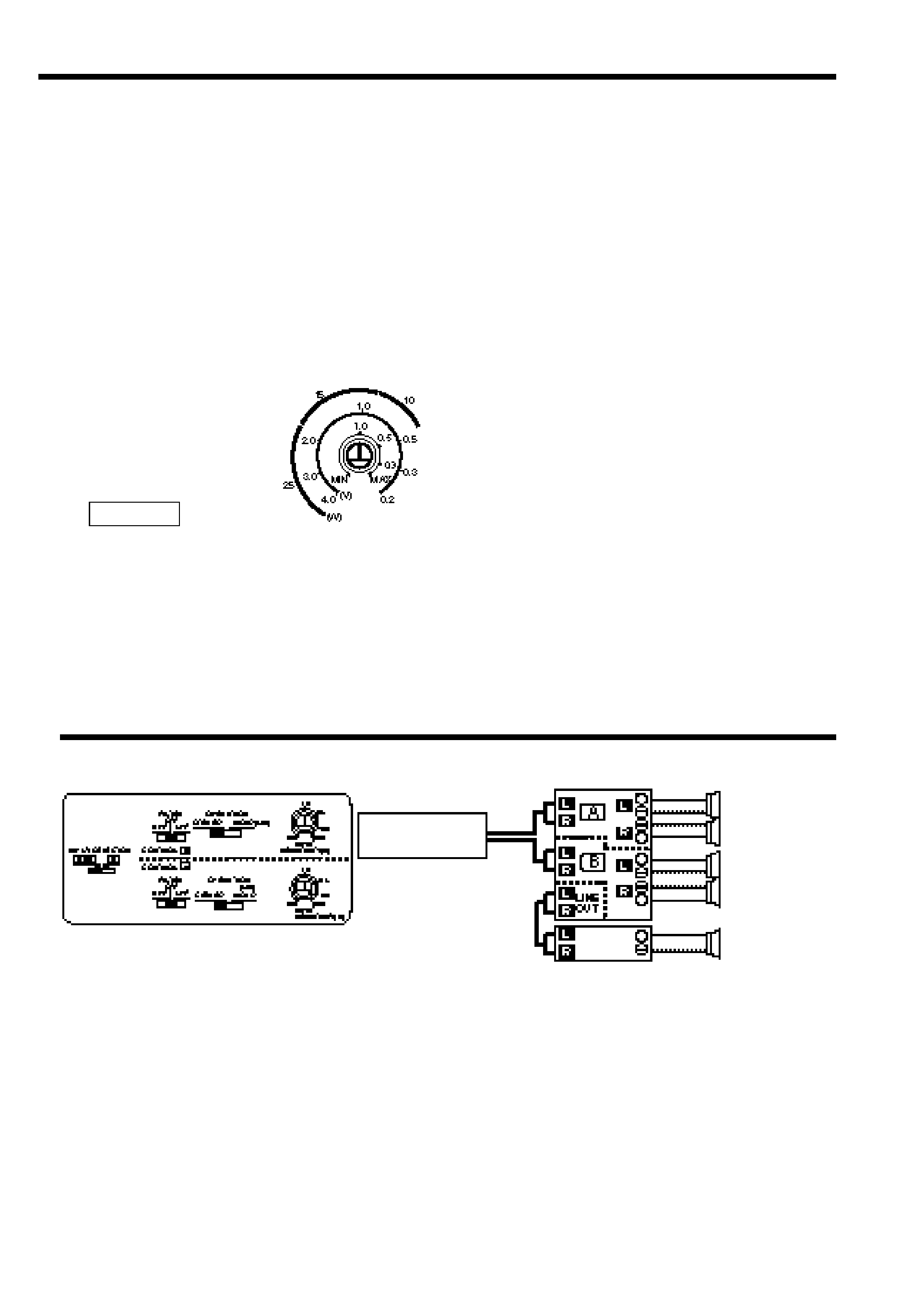
! LINE OUT terminal
These jacks output respectively the signals
input to amplifiers A and B. They always
output the stereo signals regardless of the
position of the OPERATION switch.
@ RCA cable ground lead terminal
# INPUT SENSITIVITY control
Set this control according to the pre-output
level of the center unit connected with this
unit, or to the maximum power output of
the genuine-accessory car stereo.
The sensitivities of amplifiers A and B can
be adjusted independently regardless of the
position of the input selector switch.
Use the diagram on
the right as a guide.
For the pre-output level or the maximum
power output, refer to the "Specifications"
in the instruction manual of the center unit.
$ OPERATION switch
The amplification methods of the signals
input to amplifiers A and B can be selected
independently according to the setting of
this switch.
· STEREO position:
The amplifier can be used as a stereo
amplifier.
· MONO (Lch) position:
Amplifies the signal input from the left side
only. Set to this position and make bridged
connections to use as a high-power
monaural amplifier. (The input right signal is
not output.)
% FILTER switch
These switches allow filtering of the
speaker output signals.
· HPF(High Pass Filter) position:
Only frequencies of 150Hz or higher are
output. (Frequencies below 150Hz are cut.)
· LPF(Low Pass Filter) position:
Only frequencies of 80Hz or lower are
output. (Frequencies above 80Hz are cut.)
The Lch and Rch will be mixed before
output even if the operation switch is set to
STEREO.
· OFF position:
The original sound without filtering is
output.
NOTE
English
5
System examples
s Full-range 4-channel + Subwoofer system
CENTER UNIT
Front
speaker
Rear
speaker
Subwoofer
Power amplifier
Switch setting