
KAC-726
KAC-526X
POWER AMPLIFIER
INSTRUCTION MANUAL
© B64-1213-00 (EM)
2
Safety precautions
Take the following precautions to
prevent fire and avoid personal
injury :
· When extending the battery cable, or
ground cable, use 5mm2 (AWG10) or
larger automotive grade cable to avoid
cable deterioration or damage to the
covering.
· Check that no metal objects (coins, tools,
etc.) are left inside the unit to avoid short
circuits.
· If you smell or see smoke, turn the
power off immediately and consult your
Kenwood dealer.
· Do not touch the unit during use because
the surface of the unit becomes hot and
may cause burns if touched.
Take the following precautions to
keep the unit in proper working
order.
· Be sure the unit is connected to a 12V
DC power supply with a negative ground
connection.
· Do not open the top or bottom cover.
· Do not install the unit in places it is
exposed to direct sunlight, high heat or
humidity, water may splash over it, or
dust exists.
If you have difficulty in installing this unit
in your vehicle, contact your Kenwood
dealer.
Cleaning the unit
If the surface is dirty, wipe it clean with a
silicon cloth or soft dry cloth with the
power off.
Do not use hard cloths or paint thinner,
alcohol, or other volatile solvents. These
may damage external surfaces or remove
indicator characters.
2CAUTION
NOTE
2CAUTION
2WARNING
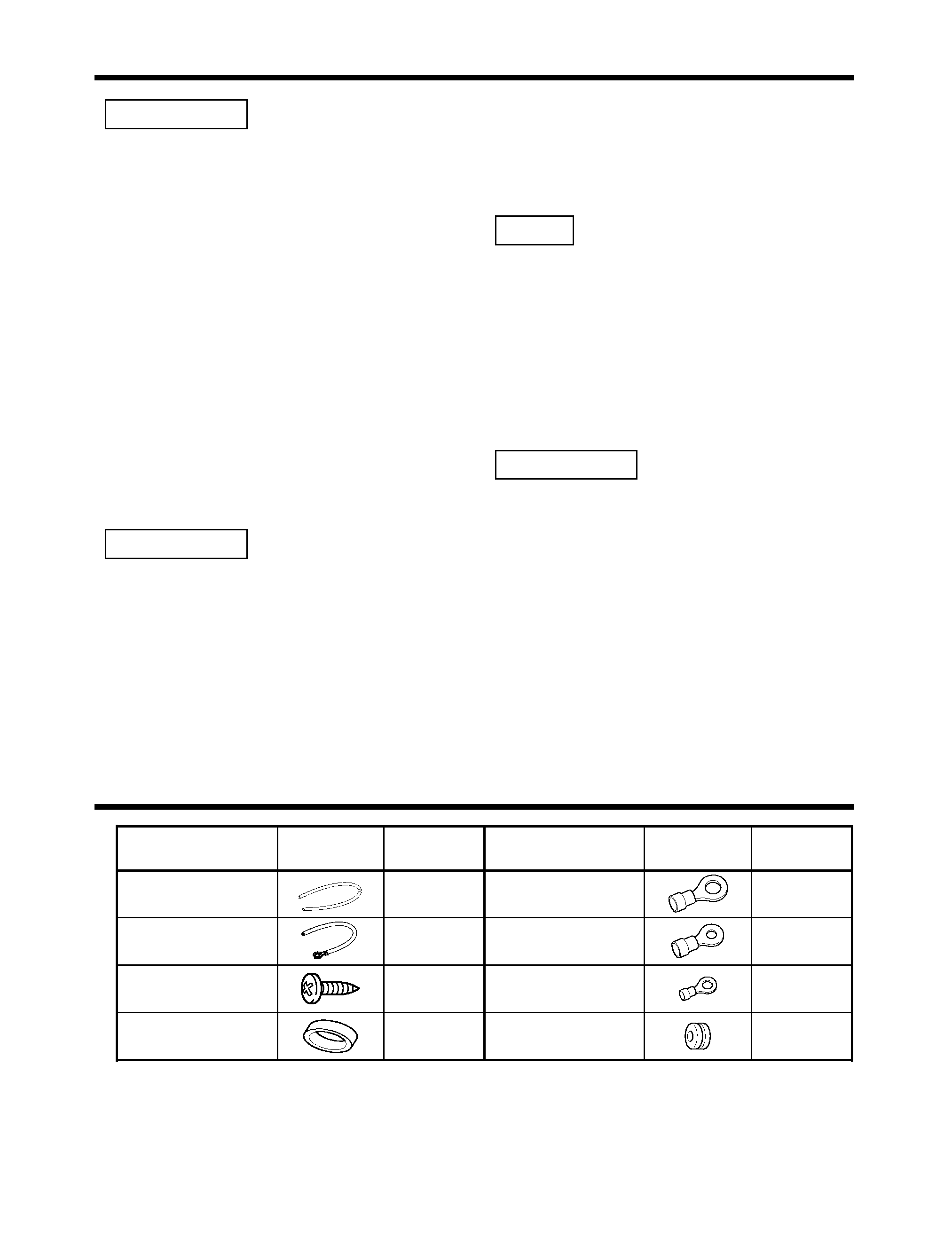
Accessories
Part name
Number
of Items
External
View
Battery cable
(Yellow) (6 m)
1
Ground cable (Black)
(1 m)
1
Self-tapping screws
(ø4
× 16 mm)
4
Terminal cover
(Power terminal)
1
Part name
Number
of Items
External
View
Round terminal
(Large)
1
Round terminal
(Medium)
2
Round terminal
(Small)
1
Grommets
1
3
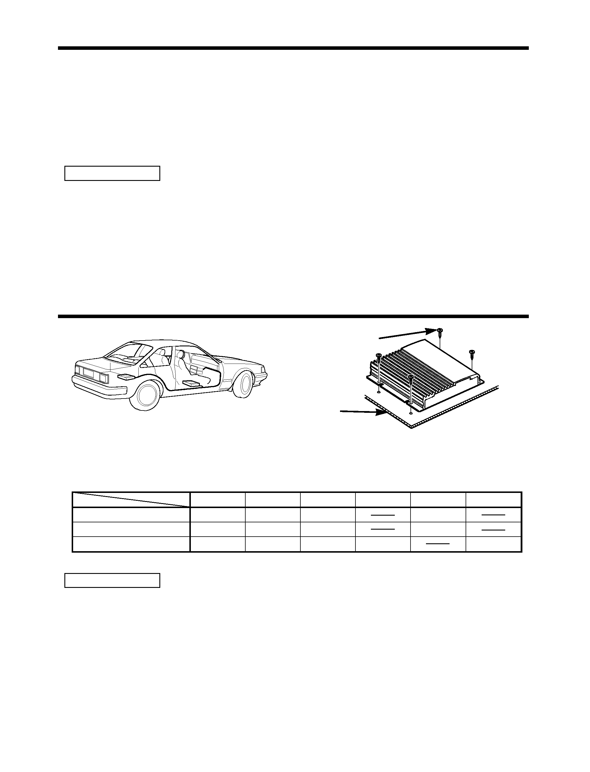
Installation procedure
1. Remove the ignition key and disconnect the negative - terminal of the battery to prevent
short circuits.
2. Set the unit according to the intended usage.
3. Connect the input and output cables of the units.
4. Connect the speaker cables.
5. Connect the power cable, power control cable and grounding cable following this order.
6. Install the unit in the car.
7. Connect the negative - terminal of the battery.
· Be sure to turn the power off before changing the setting of any switch.
· If the fuse blows, check cables for shorts, then replace the fuse with one of the same rating.
· Check that no unconnected cables or connectors are touching the car body. Do not remove
caps from unconnected cables or connectors to prevent short circuits.
· Connect the speaker cables to appropriate speaker connectors separately. Sharing the
negative cable of the speaker or grounding speaker cables to the metal body of the car can
cause this unit to fail.
· After installation, check that the brake lamps, winkers, and wipers work properly.
2CAUTION
Installation
· Since the power amplifier has no parts which require operation, it can be installed at a position
away from the driver's seat without any hindrances.
As generally accepted positions for its installation, places such as inside the trunk, etc. can be
considered.
· Use the extension cables. (Optional.)
· Do not install the unit under the carpet. Otherwise heat build-up occurs and the unit may be
damaged.
· Install this unit in a location which allows heat to easily dissipate.
Once installed, do not place any object on top of the unit.
· After installing the unit, check to make sure that electrical equipment such as the brake lamps,
turn signal lamps and windshield wipers operate normally.
· Install the unit securely in a location that does not interfere with driving.
2CAUTION
Installation board, etc.
(thickness : 15 mm or more)
Self-tapping screw
(ø4
× 16 mm)
CA-2SL
CA-12SL
CA-22SL
CA-52SL
RCA cable
CA-3WL
CA-13WL
CA-23WL
CA-53WL
RCA cable (ø7mm)
CA-5W
CA-15W
CA-25W
CA-45W
CA-65W
RCA cable (ø12mm)
0.5m
1m
2m
4m
5m
6m
Type
Length
4
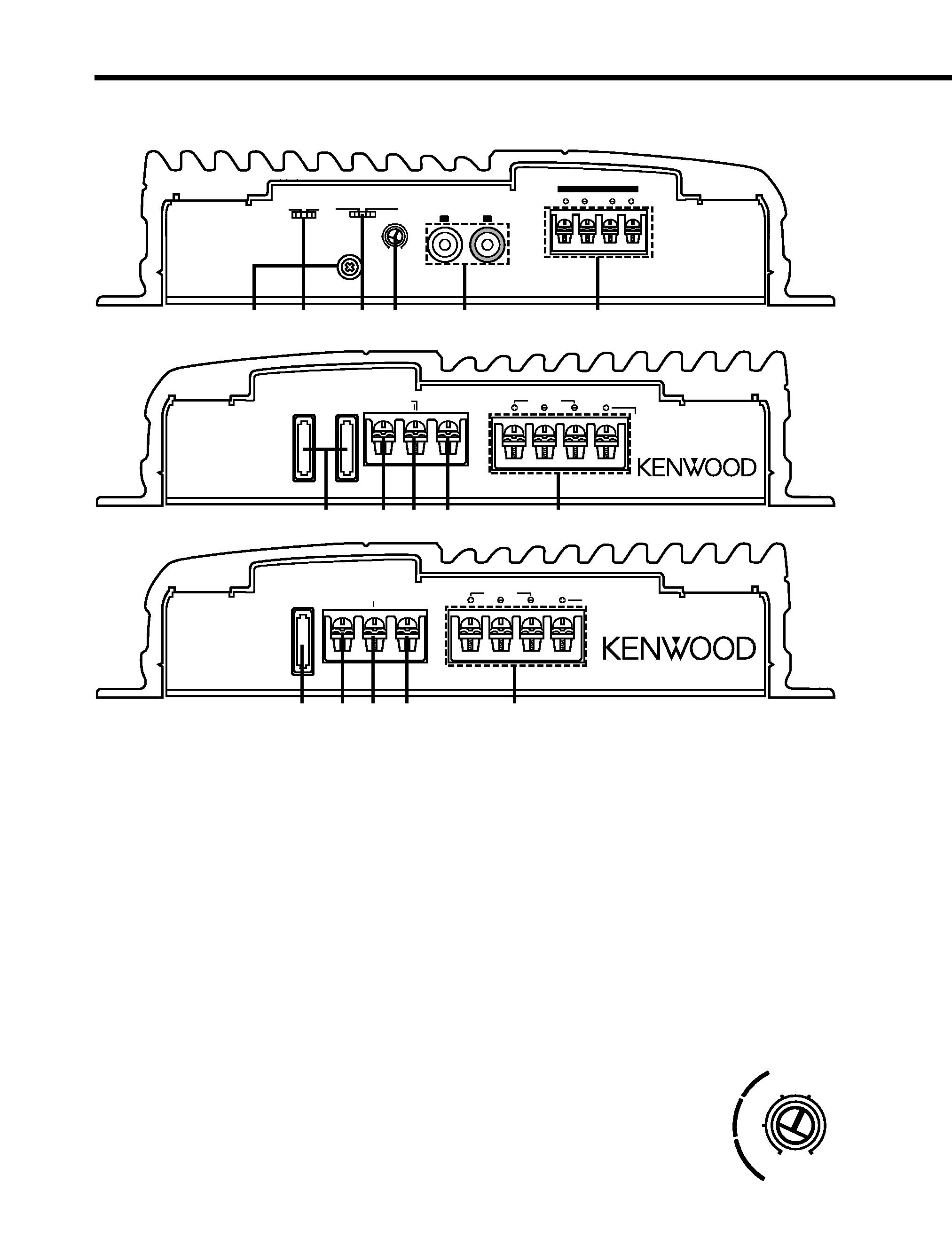
Controls
Operations of the following control and switches are required in accordance with
the center unit and speakers connected with this unit.
24
6
1
5
3
LPF
FILTER
OFF
MONO(Lch)
STEREO
OPERATION
GND
INPUT
SENSITIVITY(V)
MAX
MIN
0.3
0.5
1.0
L
R
LINE IN
LEFT
RIGHT
SPEAKER LEVEL INPUT
79
!
0
8
FUSE(20A x 2)
POWER IN
BATT
P.CON(REMOTE)
GND
LEFT
BRIDGED
RIGHT
SPEAKER OUTPUT
POWER AMPLIFIER
79
!
0
8
FUSE(15A)
POWER IN
BATT
P.CON(REMOTE)
GND
LEFT
BRIDGED
RIGHT
SPEAKER OUTPUT
POWER AMPLIFIER
KAC-526X
1 RCA cable ground lead terminal
2 FILTER switch
These switches allow filtering of the speaker output signals.
· LPF (Low Pass Filter) position
Only frequencies of 80 Hz or lower are output. (Frequencies above 80 Hz are cut.)
The Lch and Rch will be mixed before output even if the operation switch is set to STEREO.
· OFF position
The original sound without filtering is output.
3 OPERATION switch
This switch allows selection of the amplification method of input signals.
· STEREO position
The amplifier can be used as a stereo amplifier.
· MONO (Lch) position
Amplifies the signal input from the left side only. Set to this position and make bridged
connections to use as a high-power monaural amplifier. (The input right signal is not output.)
4 INPUT SENSITIVITY control
Set this control according to the pre-output level of the center unit
connected with this unit, or to the maximum power output of the genuine-
accessory car stereo.
Use the diagram on the right as a guide.
MAX
MIN
0.3
0.5
1.0
(W)
25
15
10
KAC-726
KAC-726
KAC-526X
5
For the pre-output level or the maximum power output, refer to the "Specifications" in the
instruction manual of the center unit.
5 LINE IN terminal
6 Speaker level input terminals
7 Fuse (20 A
× 2 : KAC-726)
Fuse (15 A : KAC-526X)
8 Battery terminal
9 Ground terminal
0 Power control (REMOTE) terminal
! SPEAKER OUTPUT terminals
NOTE
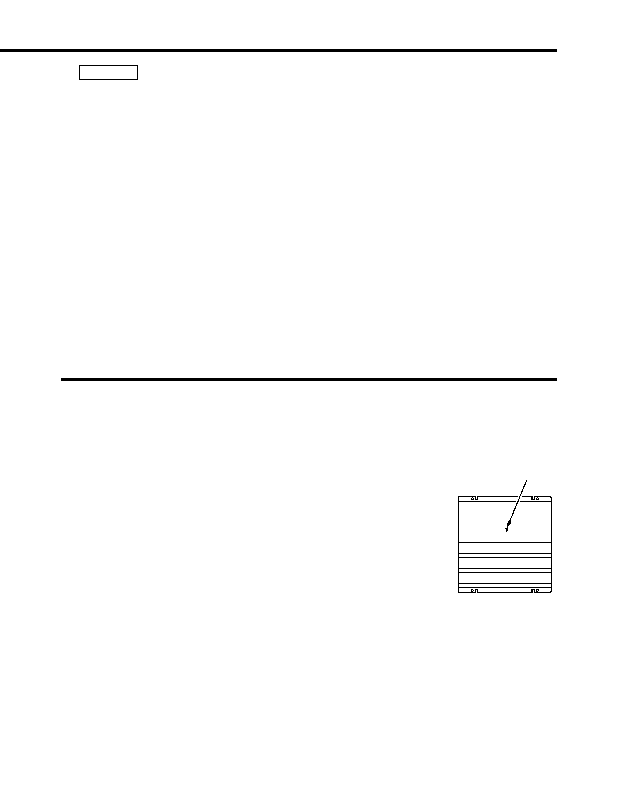
Protection function
This unit is equipped with a protection function for protecting this unit and your
speakers from various accidents or problems that can occur.
When the protection function is triggered, the Power indicator goes off and the
amplifier stops operating.
s Power indicator:
When the power is turned on, the Power indicator lights.
If the Power indicator does not light when the power is turned on, the
protection function may be activated. Check whether there is any
indication of trouble.
s The protection function activates in the following
situations:
· When a speaker output contacts ground.
· When the unit malfunctions and a DC signal is sent to the speaker output.
· When the temperature of internal parts exceeds 120°C (248°F).
· When a ground cable of the center unit (cassette receiver, CD receiver,
etc.) or this unit is not connected to a metal part serving as an electrical
ground passing electricity to the battery's negative - terminal.
Power indicator