
KAC-210MR
SUBWOOFER POWER AMPLIFIER
7 page 2-7
INSTRUCTION MANUAL
AMPLIFICATEUR DE PUISSANCE DU SUBWOOFER
7 page 8-13
MODE D'EMPLOI
AMPLIFICADOR DE POTENCIA DEL ALTAVOZ DE SONIDO
ENVOLVENTE
7 página 14-19
MANUAL DE INSTRUCCIONES
© B64-3090-00/00 (KV)
Take the time to read through this instruction manual.
Familiarity with installation and operation procedures will help
you obtain the best performance from your new power amplifier.
For your records
Record the serial number, found on the back of the unit, in the spaces
designated on the warranty card, and in the space provided below.
Refer to the model and serial numbers whenever you call upon your
KENWOOD dealer for information or service on the product.
Model KAC-210MR
Serial number

2 | English
IMPORTANT SAFEGUARDS
¤ Read this page carefully to keep your
safety.
¤WARNING
· Before mounting or wiring etc., be sure to remove
the wire from the battery minus terminal.
(Not doing so can cause shorts or fires.)
· When extending the ignition, battery, or ground
wires, make sure to use automotive-grade wires
or other wires with a 0.75mm² (AWG18) or more
to prevent wire deterioration and damage to the
wire coating.
· To prevent a short circuit, never put or leave any
metallic objects (such as coins or metal tools)
inside the speaker.
· Abnormal smell In the event the unit
generates smoke or abnormal smell, immediately
switch the power OFF. After this, please contact
your dealer or nearest service station as soon as
possible.
· Power supply voltage Be sure the unit is
connected to a 12V DC power supply with a
negative ground connection.
· Modification Do not attempt to open or
modify the unit, for this could cause fire hazard or
malfunction.
· Suffocation After taking the unit out of the
polyethylene bag, be sure to dispose of the
polyethylene bag out of the reach of children.
Otherwise, they may play with the bag, which
could cause hazard of suffocation.
FCC WARNING
This equipment may generate or use radio
frequency energy. Changes or modifications to
this equipment may cause harmful interference
unless the modifications are expressly approved
in the instruction manual. The user could lose
the authority to operate this equipment if an
unauthorized change or modification is made.
¤CAUTION
· Dust and unstable locations Do not install the
speakers in unstable locations or locations subject
to dust.
· If the fuse blows, after checking to see if the
wiring cord has shorted, be sure to replace with
the stipulated size (amperage) fuse as displayed
on the fuse box.
(Using fuses other than the stipulated size can
cause fires.)
To replace the fuse, refer to the vessel instruction
manual.
· To prevent a short circuit when replacing a fuse,
disconnect the wiring harness at first.
· Do not use gasoline, naphtha, or any type of
solvent to clean the speaker. Clean by wiping with
a soft, dry cloth.
· Connect the speaker input wires to appropriate
speaker connectors separately. Sharing the
negative wire of the speaker or grounding speaker
wires to the metal body of the car can cause this
unit to fail.
· Do not connect cables and leads to both RCA
cable input jacks and the speaker input terminals
simultaneously, for this may cause malfunction or
damage.
· When making a hole in the vessel, check that
there is nothing hazardous on the opposite side
such as a gasoline tank, or wiring harness, and be
careful not to cause scratches or other damage.
· For ground wire mounting, do not fasten the wire
to an steering or other critical safety unit bolts or
nut.
(Can cause accidents.)
· When mounting, be sure to mount in a place that
will not interfere with driving or be dangerous to
passengers during sudden movement etc.
(Cause of injury or accidents.)
· After installing the unit, check to make sure that
electrical equipment such as the turn signal lamps
and gauges operate normally.
English
|
3
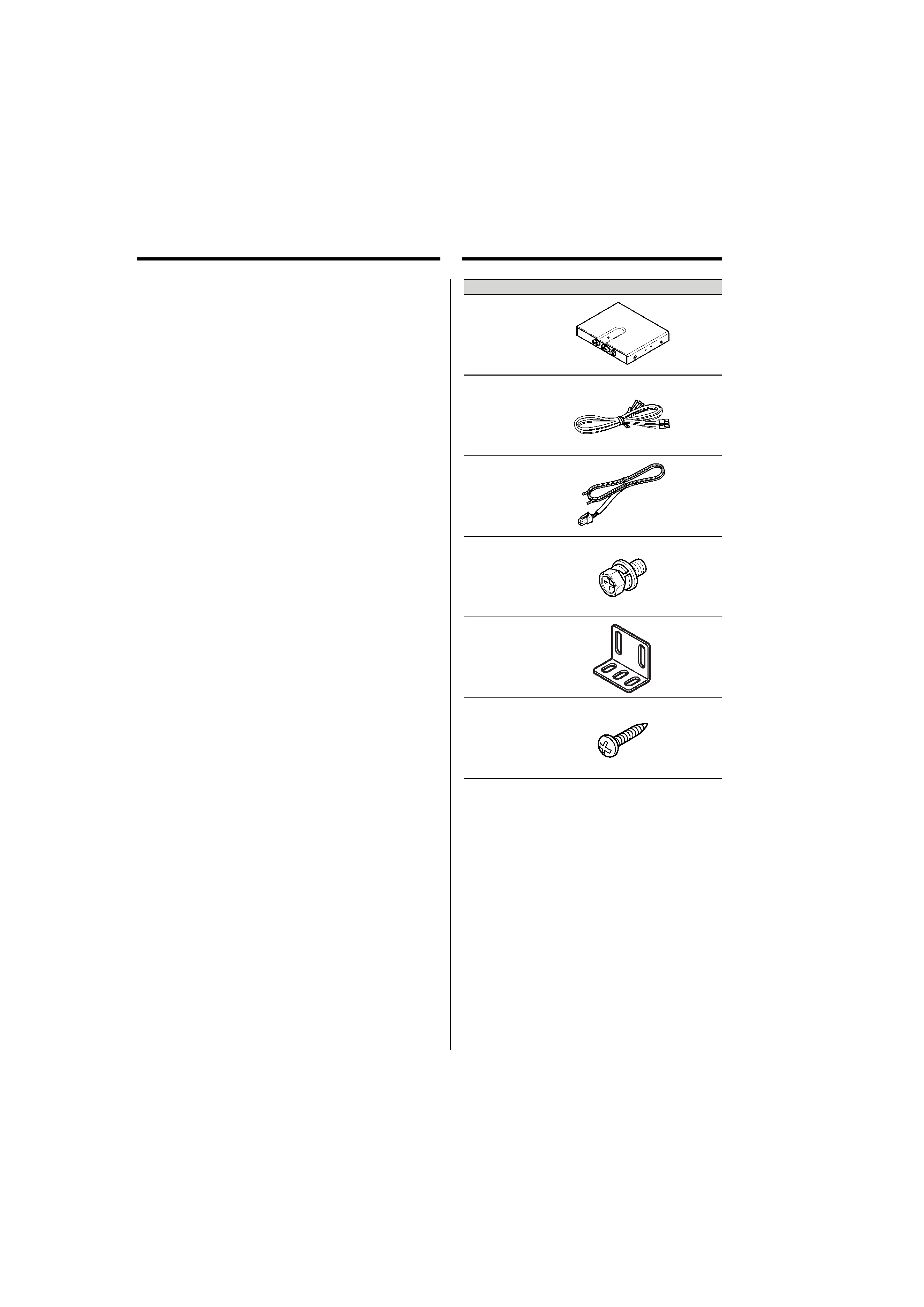
No.
Part Name
Outside Shape
Quantity
1
Amplifier
1
2 10-pin connector cord
1
3 Speaker cord (0.4m)
1
4
Machine screw
(M4 × 8mm)
4
5
Bracket
2
6
Tap screw
(Ø4 × 16mm)
4
Parts included
4 | English
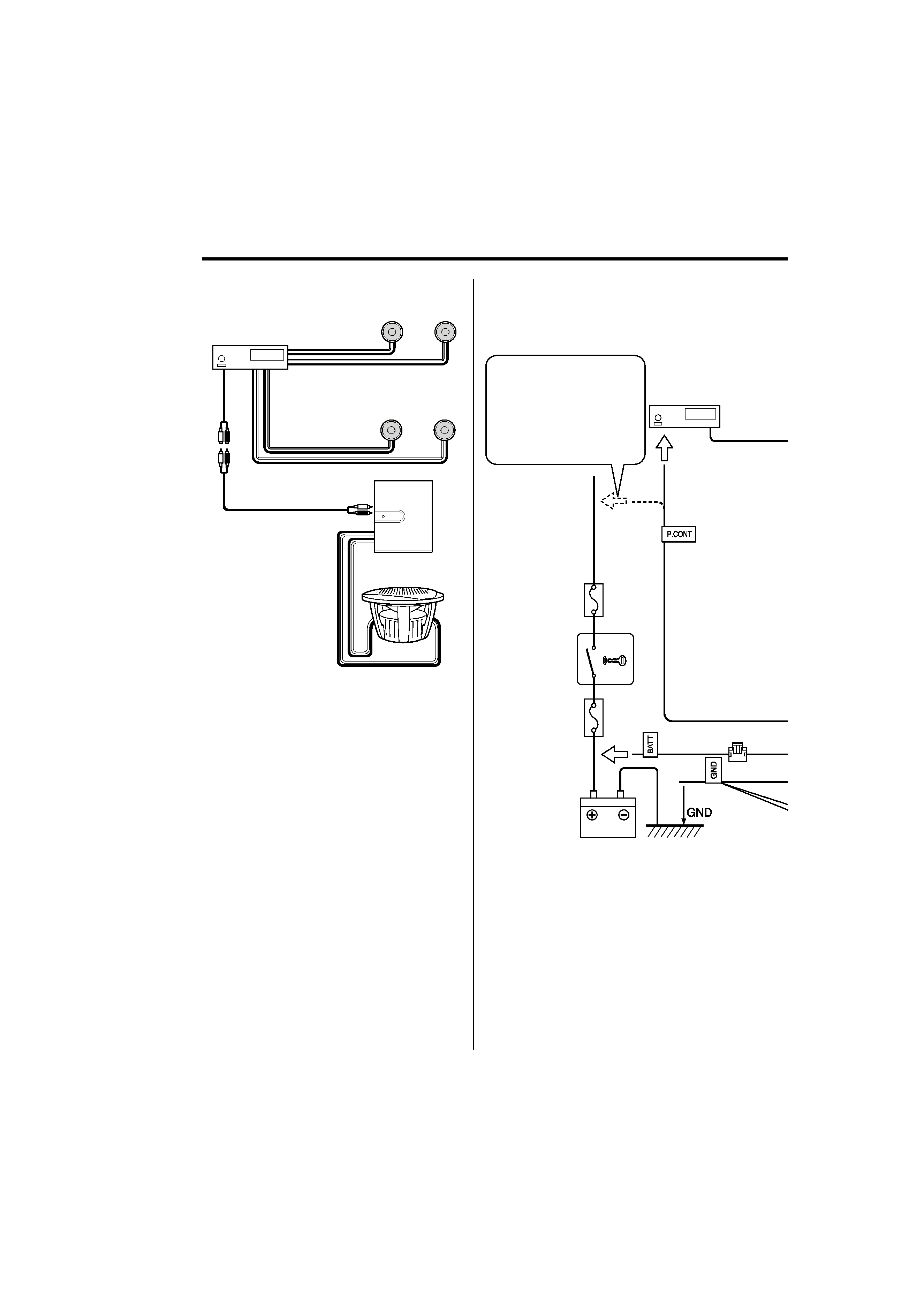
Connection
Front speaker
Rear speaker
CENTER UNIT
RCA cord
(Commercially
available parts)
KFC-W250MRW
1 Amplifier
Examples of applications
CENTER UNIT
Fuse 5A × 2
· If there is no power control
terminal in the center unit,
connect the blue/white wire
to the accessory line (ignition
key switch ACC position line).
Car fuse box
Ignition key
switch
Car fuse box
(Main fuse)
Battery
To the power
control terminal
Examples of Connections
(1.5 Dual Voice Coil Woofer only)
English
|
5
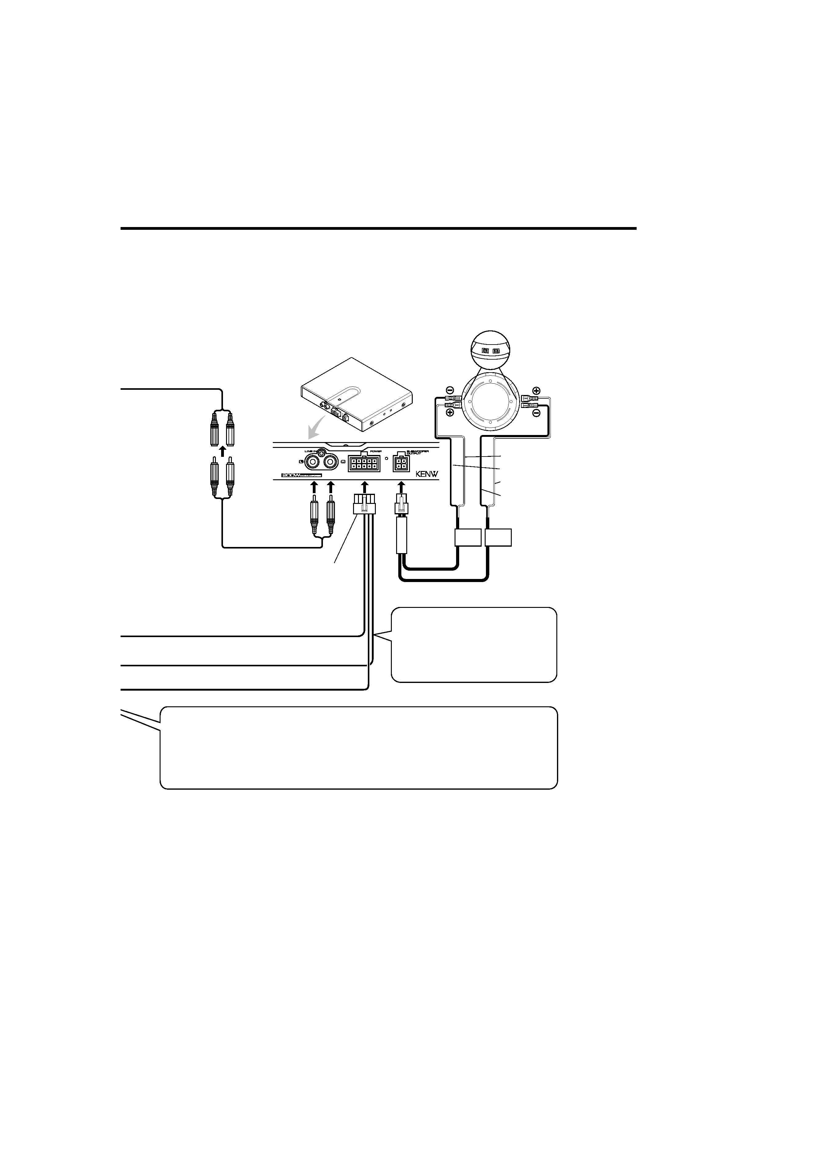
SUBWOOFER OUT
Black
2 10-pin connector cord
3 Speaker cord
Yellow
RCA cord
(Commercially
available parts)
Blue / white
Caution
· Connect the black lead wire ground terminal directly with a screw to a negative ground
point of the vessel. Turning the power ON without connecting this terminal is linked to
damage of the stereo system. Be sure to connect it.
Also, painted metal panels etc., are not grounded and will not function correctly. Be
careful.
· If buzzing noise is heard from
the speakers when the engine is
running, attach a line noise filter
(sold separately) to the power
lead.
KFC-W250MRW
Green
Green / Black
Purple / Black
Purple