SERVICE MANUAL
COPYRIGHT © 2003 VICTOR COMPANY OF JAPAN, LTD.
No.49858
2003/5
CD RECEIVER
49858
2003
5
KD-S845
TABLE OF CONTENTS
1
Important Safety Precautions . . . . . . . . . . . . . . . . . . . . . . . . . . . . . . . . . . . . . . . . . . . . . . . . . . . . . . . . . . . . . 2
2
Disassembly method . . . . . . . . . . . . . . . . . . . . . . . . . . . . . . . . . . . . . . . . . . . . . . . . . . . . . . . . . . . . . . . . . . . . 4
3
Adjustment. . . . . . . . . . . . . . . . . . . . . . . . . . . . . . . . . . . . . . . . . . . . . . . . . . . . . . . . . . . . . . . . . . . . . . . . . . . . 12
4
Description of major ICs . . . . . . . . . . . . . . . . . . . . . . . . . . . . . . . . . . . . . . . . . . . . . . . . . . . . . . . . . . . . . . . . . 16
45Wx4
TU NER
SCM
RND
RPT
12
11
10
9
8
7
KD-S845
BAND
U ------- Other Areas
Area Suffix
1-2 (No.49858)
SECTION 1
Important Safety Precautions
1.1
Safety Precautions
!
Burrs formed during molding may be left over on some parts of the chassis. Therefore,
pay attention to such burrs in the case of preforming repair of this system.
!
Please use enough caution not to see the beam directly or touch it in case of an
adjustment or operation check.
(No.49858)1-3
1.2
Preventing static electricity
Electrostatic discharge (ESD), which occurs when static electricity stored in the body, fabric, etc. is discharged, can destroy the laser
diode in the traverse unit (optical pickup). Take care to prevent this when performing repairs.
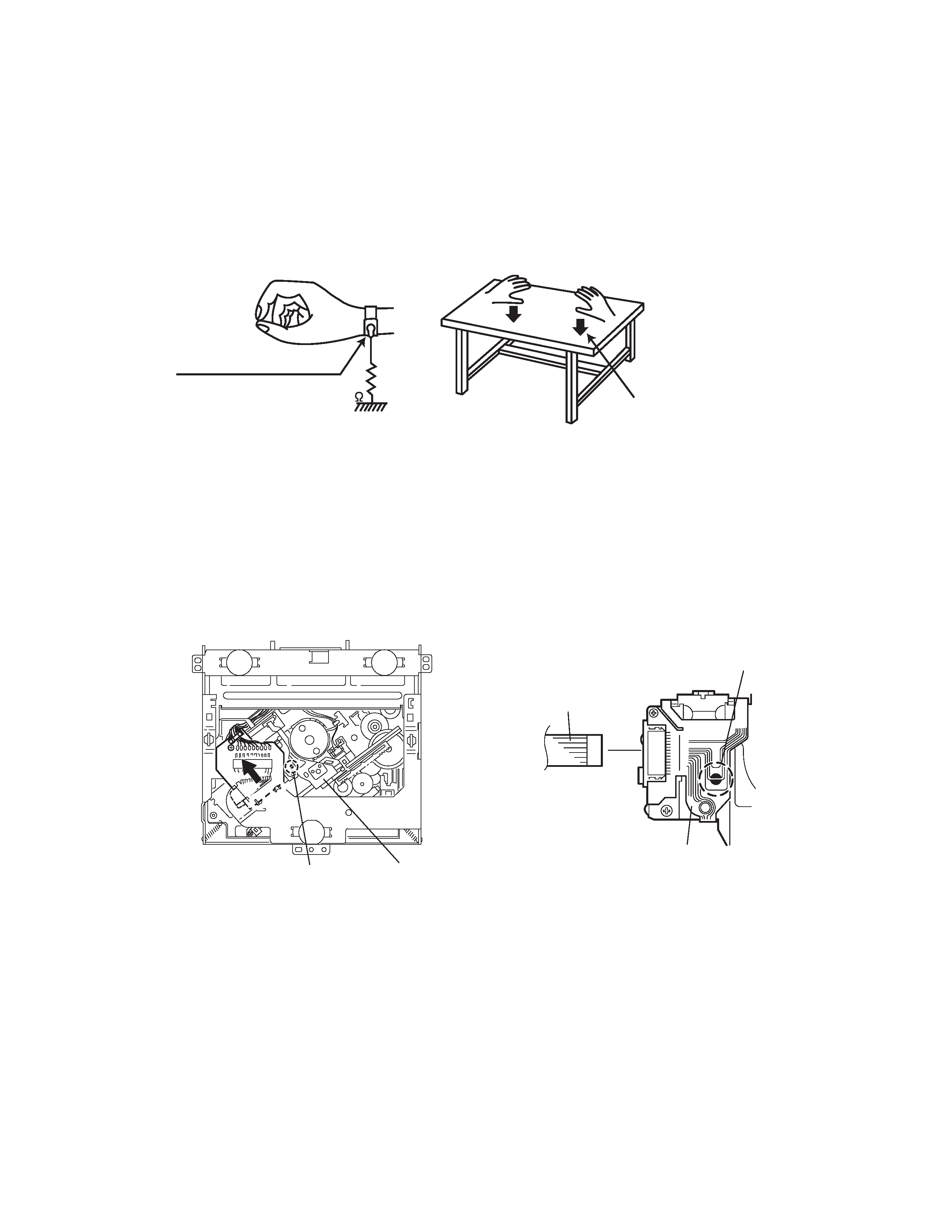
1.2.1
Grounding to prevent damage by static electricity
Static electricity in the work area can destroy the optical pickup (laser diode) in devices such as DVD players.
Be careful to use proper grounding in the area where repairs are being performed.
(1) Ground the workbench
Ground the workbench by laying conductive material (such as a conductive sheet) or an iron plate over it before placing the
traverse unit (optical pickup) on it.
(2) Ground yourself
Use an anti-static wrist strap to release any static electricity built up in your body.
(3) Handling the optical pickup
· In order to maintain quality during transport and before installation, both sides of the laser diode on the replacement optical
pickup are shorted. After replacement, return the shorted parts to their original condition.
(Refer to the text.)
· Do not use a tester to check the condition of the laser diode in the optical pickup. The tester's internal power source can easily
destroy the laser diode.
1.3
Attention when traverse unit is decomposed
*Please refer to "Disassembly method" in the text for the CD pickup unit.
· Apply solder to the short land before the flexible wire is disconnected from the connector on the CD pickup unit.
(If the flexible wire is disconnected without applying solder, the CDpickup may be destroyed by static electricity.)
· In the assembly, be sure to remove solder from the short land after connecting the flexible wire.
1M
(caption)
Anti-static wrist strap
Conductive material
(conductive sheet) or iron plate
Pickup
Short-circuit point
(Soldering)
Flexible wire
Pickup
Short-circuit point
1-4 (No.49858)
SECTION 2
Disassembly method
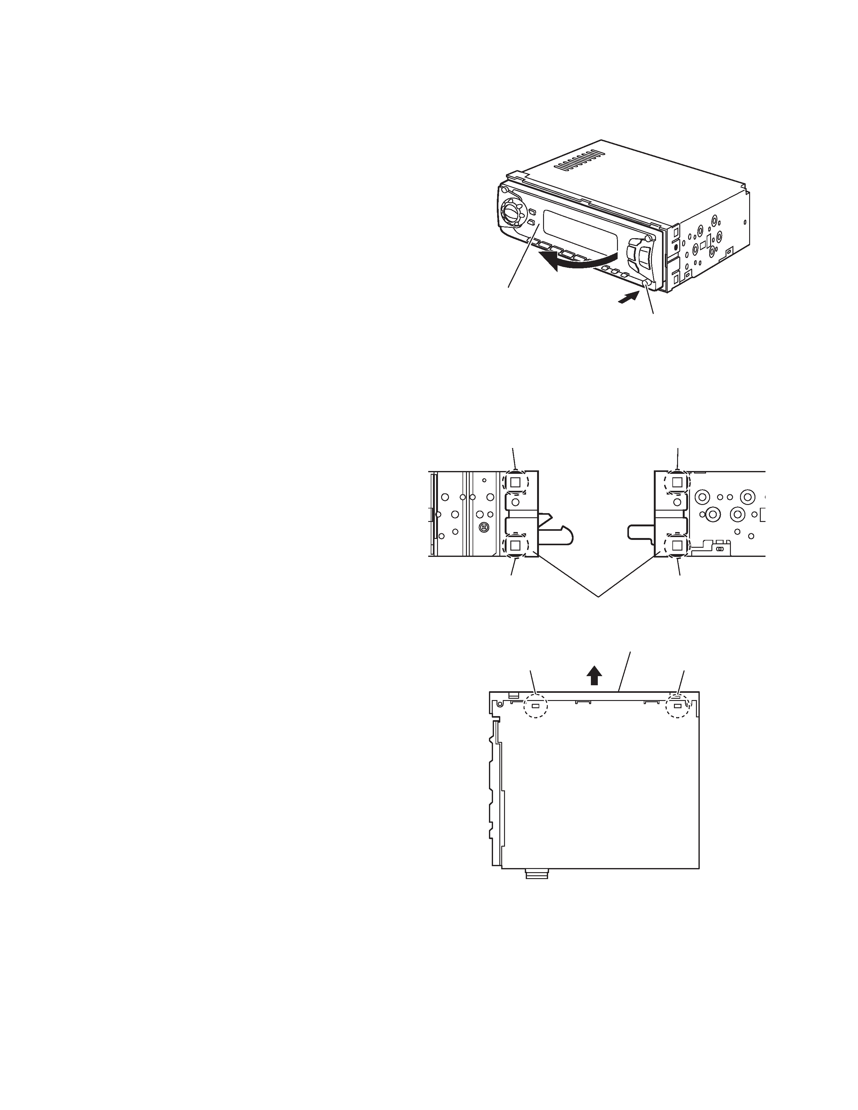
2.1
Main body
2.1.1
Removing the front panel assembly
(See Fig.1)
(1) Push the detach button in the lower left part of the front
panel and remove the front panel assembly in the direction
of the arrow.
Fig.1
2.1.2
Removing the front chassis assembly
(See Figs.2 to 3)
· Prior to performing the following procedure, remove the front
panel assembly.
(1) Release the two joints a and two joints b on both sides of
the main body.
(2) Release the two joints c on the bottom side of the main
body and remove the front chassis assembly in the direc-
tion of the arrow.
Fig.2
Fig.3
Front panel assembly
Eject button
Joint
a
Joint
a
Front chassis assembly
Joint
b
Joint
b
Front chassis assembly
Joint c
Joint c
(No.49858)1-5
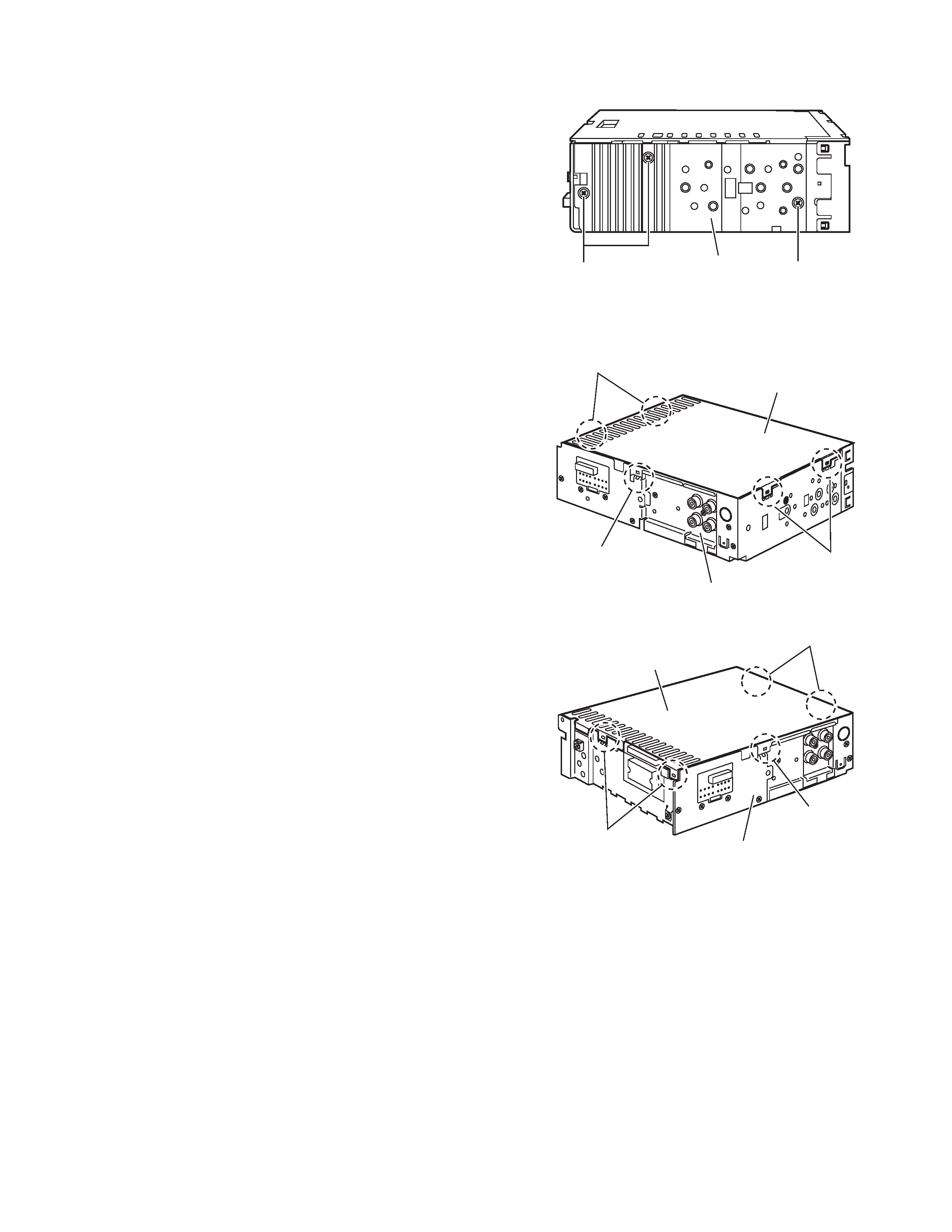
2.1.3 Removing the heat sink
(See Fig.4)
(1) Remove the three screws A on the left side of the main
body.
Fig.4
2.1.4 Removing the bottom cover
(See Figs.5 and 6)
· Prior to performing the following procedure, remove the front
panel assembly, front chassis assembly and heat sink.
(1) Turn over the main body and release the two joints d, two
joints e and joint f.
CAUTION:
Do not damage the main board when releasing the joint f using
a screwdriver. (See Figs.5 and 6)
Fig.5
Fig.6
Heat sink
A
A
Joint d
Joint e
Joint f
Bottom cover
Rear panel
Joint e
Joint d
Joint f
Rear panel
Bottom cover