SERVICE MANUAL
CD RECEIVER
No.49666
Dec. 2001
COPYRIGHT
2001 VICTOR COMPANY OF JAPAN, LTD.
KD-S6250 / KD-S580
KD-S6250/KD-S580
Area Suffix
J ------ Northern America
KD-S6250
KD-S580
31
FM
CD
AM
SSM
KD-S6250
DIRECT
TRACK
ACCESS
MO
RPT
RND
MODE
SCM
FM
CD
AM
SSM
KD-S580
DIRECT
TRACK
ACCESS
MO
RPT
RND
MODE
SCM
Contents
Safety precaution
Preventing static electricity
Disassembly method
Adjustment method
1-2
1-3
1-4
1-11
Flow of functional
operation unit TOC read
Maintenance of laser pickup
Replacement of laser pickup
Description of major ICs
1-12
1-14
1-14
1-15
Difference point
KD-S6250
KD-S580
Color
Silver
Metallic gray
Remocon
KD-S6250/KD-S580
1-4
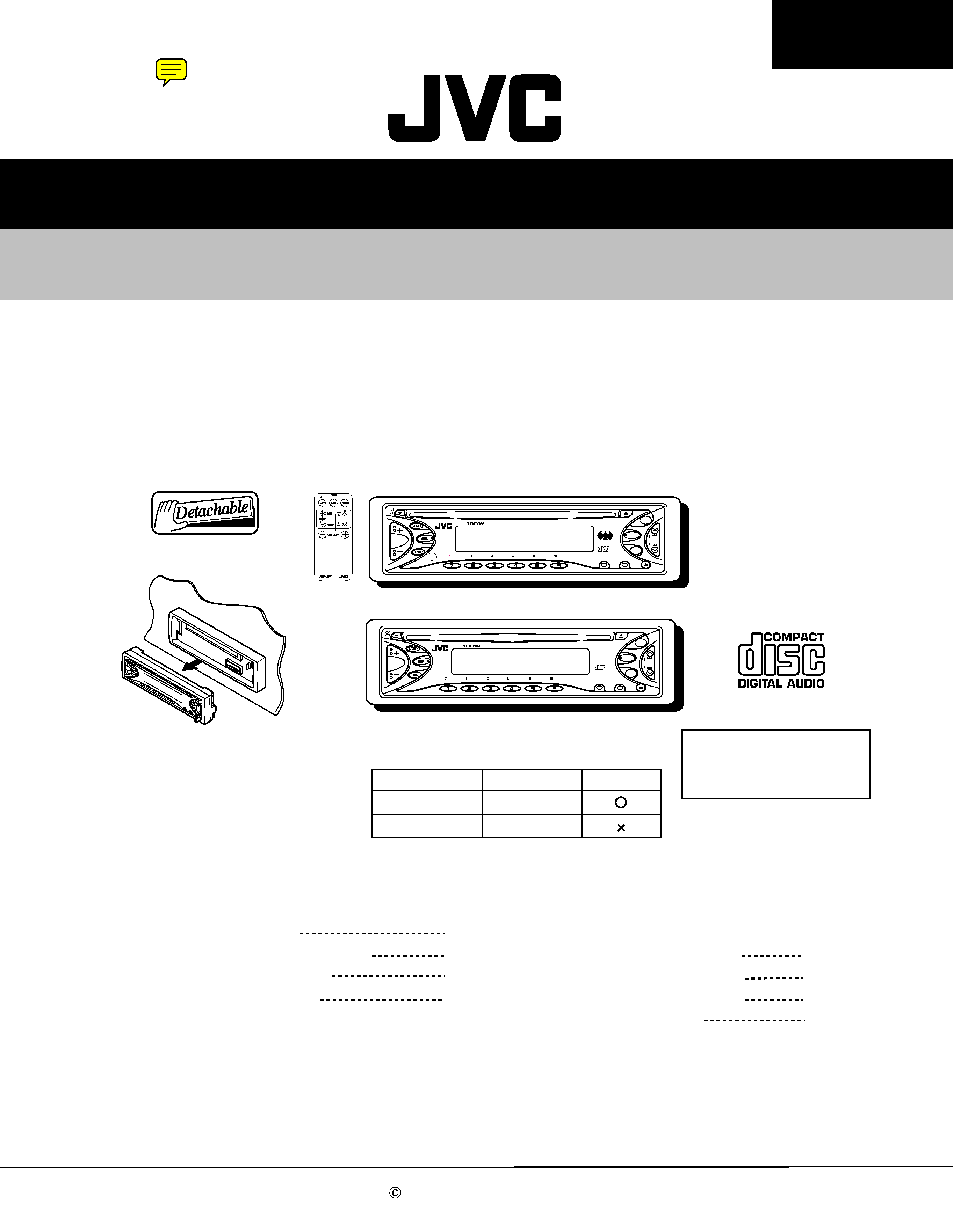
Press the eject button in the lower right part of the
front panel. Remove the front panel assembly from
the body.
1.
Removing the front panel assembly
(See Fig.1)
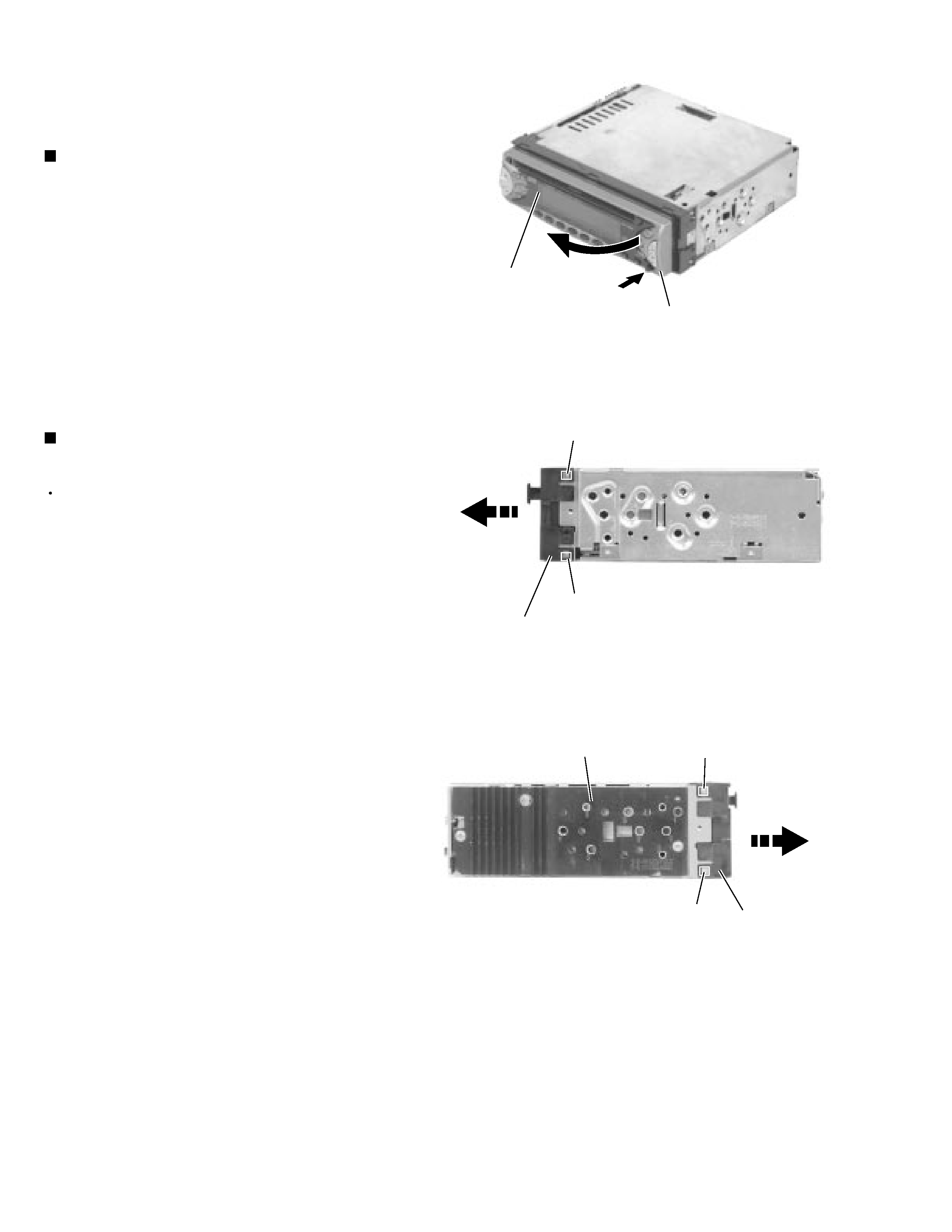
Prior to performing the following procedure, remove
the front panel assembly.
Release the four joint tabs a on both sides of the
front chassis assembly and remove the front chassis
assembly toward the front.
1.
Removing the front chassis assembly
(See Fig.2 and 3)
Disassembly method
<Main body>
Fig.1
Fig.2
Fig.3
Front panel assembly
Eject button
Tab a
Tab a
Front chassis assembly
Front chassis
assembly
Heat sink
Tab a
Tab a
KD-S6250/KD-S580
1-5
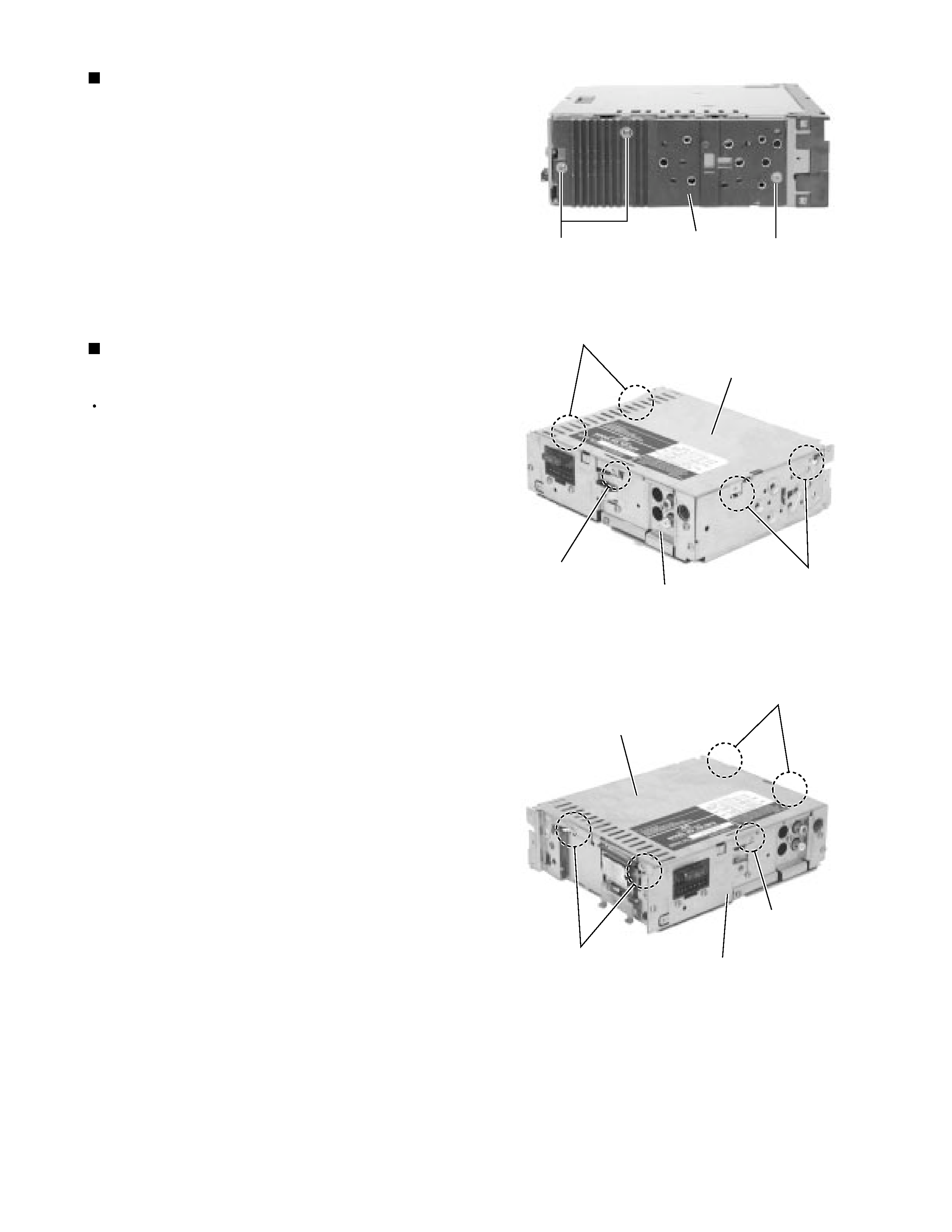
Remove the three screws A on the left side of the
body.
1.
Removing the heat sink (See Fig.4)
Prior to performing the following procedure, remove
the front panel assembly, the front chassis assembly
and the heat sink.
Turn over the body and unjoint the five joints b with
the bottom cover and the body using a screwdriver.
1.
Removing the bottom cover
(See Fig.5 and 6)
Fig.4
Fig.5
Fig.6
Heat sink
A
A
Joints b
Joints b
Joint b
Joints b
Joints b
Joint b
Bottom cover
Bottom cover
Rear panel
Rear panel
KD-S6250/KD-S580
1-6
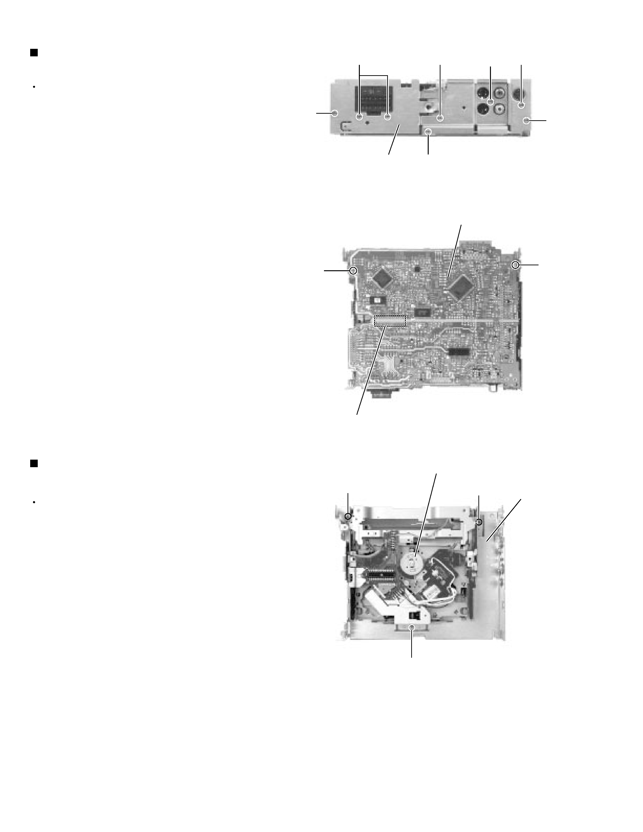
Prior to performing the following procedure, remove
the front panel assembly, the front chassis assembly,
the heat sink and the bottom cover.
Remove the screw B, the four screws C
and the
three screws D
attaching the rear bracket on the
back of the body. Remove the rear panel.
Remove the two screws E attaching the main board
on the bottom of the body. Disconnect connector
CN501 on the main board in the direction of the
arrow.
1.
2.
Removing the main board
(See Fig.7 and 8)
Prior to performing the following procedure, remove
the front panel assembly, the front chassis assembly,
the heat sink, the bottom cover and the main board.
Remove the three screws F attaching the cassette
mechanism section on the back of the top chassis.
1.
Removing the CD mechanism section
(See Fig.9)
Fig.7
Fig.8
Fig.9
Rear panel
B
D
D
D
C
Main board
E
E
CN501
CD mechanism section
F
F
F
Top chassis
C
C
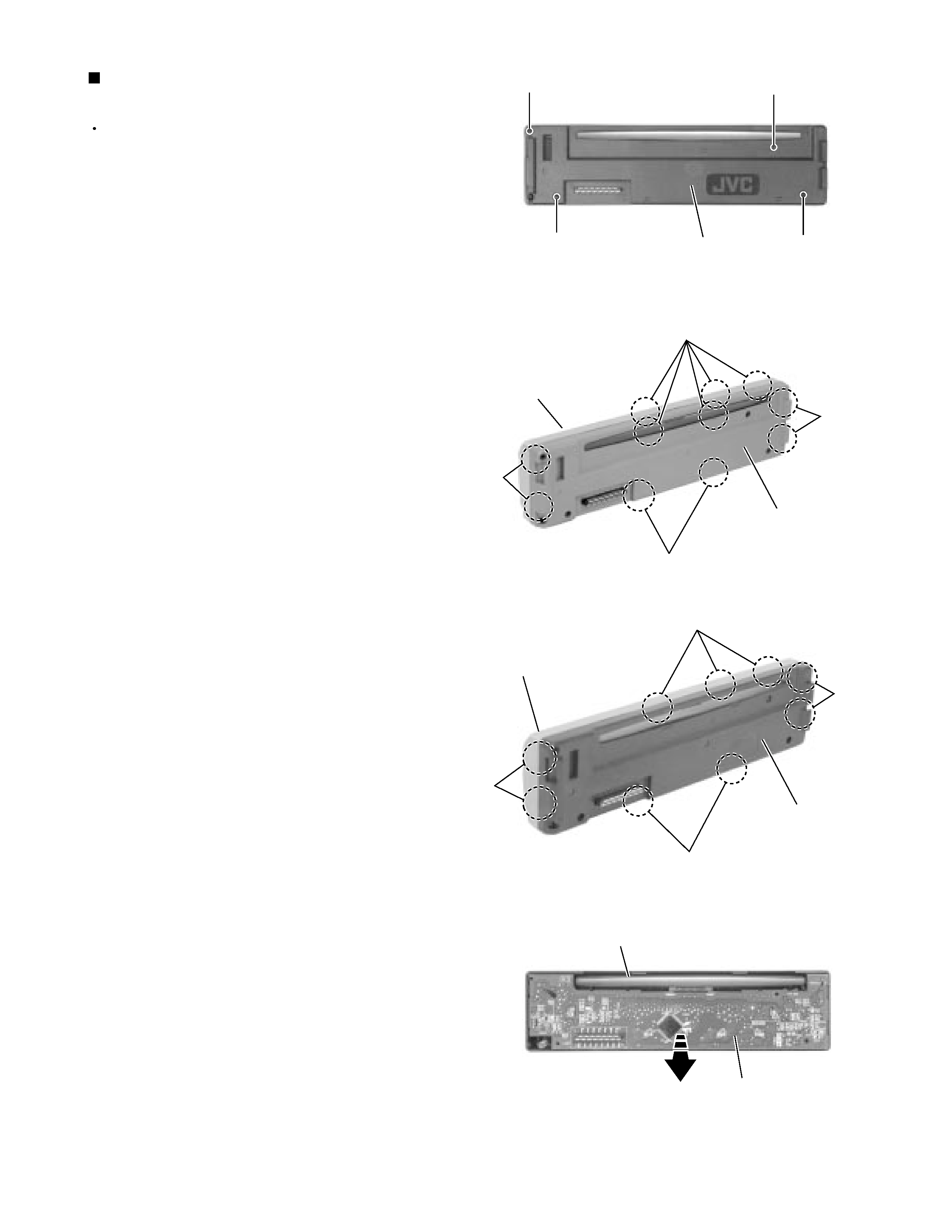
KD-S6250/KD-S580
1-7
Prior to performing the following procedure, remove
the front panel assembly.
Remove the four screws G attaching the rear cover
on the back of the front panel assembly.
Unjoint the eleven(KD-S625)or nine(KD-S580) joints
c with the front panel and the rear cover.
Remove the control switch board on the back of the
front panel.
1.
2.
3.
Removing the control switch board
(See Fig.10 to 12)
Fig.10
Fig.11
Fig.12
G
G
G
G
Rear cover
Joints c
Joints c
Front panel
Rear cover
Front panel
Control switch board
Joints c
Joints c
Joints c
Joints c
Front panel
Rear cover
Joints c
Joints c
(KD-S6250)
(KD-S580)