SERVICE MANUAL
CD RECEIVER
No.49650
Jul. 2001
COPYRIGHT
2001 VICTOR COMPANY OF JAPAN, LTD.
KD-S576
KD-S576
Contents
Safety precaution
Location of main parts
Disassembly method
Adjustment method
Flow of functional operation until TOC read
Maintenance of laser pickup
Replacement of laser pickup
Description of major ICs
1-2
1-3
1-4
1-9
1-10
1-12
1-12
1-13
COMPACT
DIGITAL AUDIO
KD-S576
31
Area Suffix
J
Northern America
(Paraguay)
KD-S576
1-2
!
Burrs formed during molding may be left over on some parts of the chassis. Therefore,
pay attention to such burrs in the case of preforming repair of this system.
Safety precaution
!
Please use enough caution not to see the beam directly or touch it in case of an
adjustment or operation check.
KD-S576
1-3
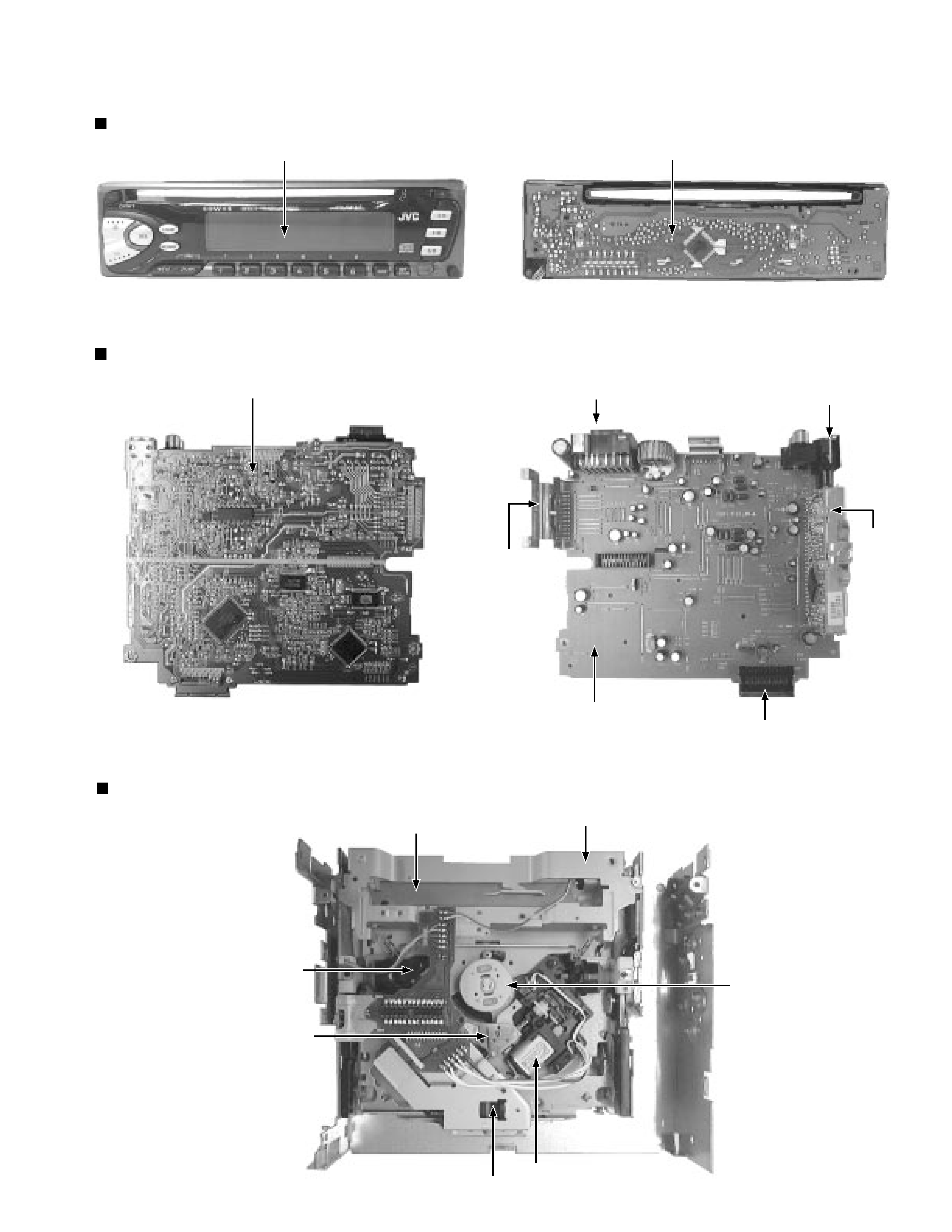
Main unit
Location of main parts
Control unit
CD mechanism
LED & key control board
Main board
Tuner
pack
Main board
Connector to controller
Power IC
ISO connector
Antenna jack
Loading motor
Mechanism relay board
Damper
Optical pick up unit
Damper
Feed motor
Spindle motor
Display
KD-S576
1-4
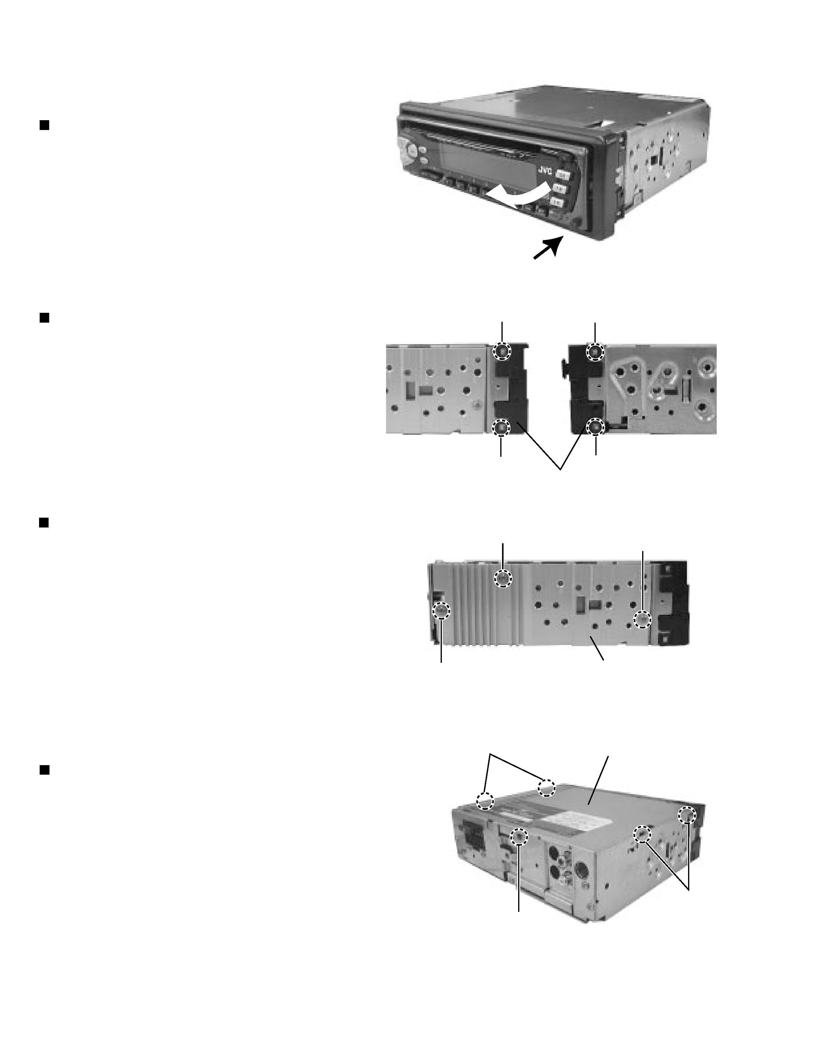
Disassembly method
Removing the front panel unit
(See Fig.1)
1. Insert a screwdriver to the joints a on the side of the
front chassis and two joints b on the right side, then
detach the front chassis toward the front side.
1. Press the release switch and remove the front
panel unit in the direction of the arrow.
Removing the front chassis (See Fig.2)
Removing the heat sink (See Fig.3)
1. Remove the three screws A attaching the heat sink
on the left side of the body, and remove the heat
sink.
Removing the bottom cover (See Fig.4)
1.
2.
Turn the body upside down.
Insert a screwdriver to the two joints c and two
joints d on both sides of the body and the joint e on
the back of the body, then detach the bottom cover
from the body.
b
a
a
b
A
A
A
Heat sink
c
d
e
Fig.2
Fig.1
Fig. 3
Fig. 4
Regulator board
Front chassis
KD-S576
1-5
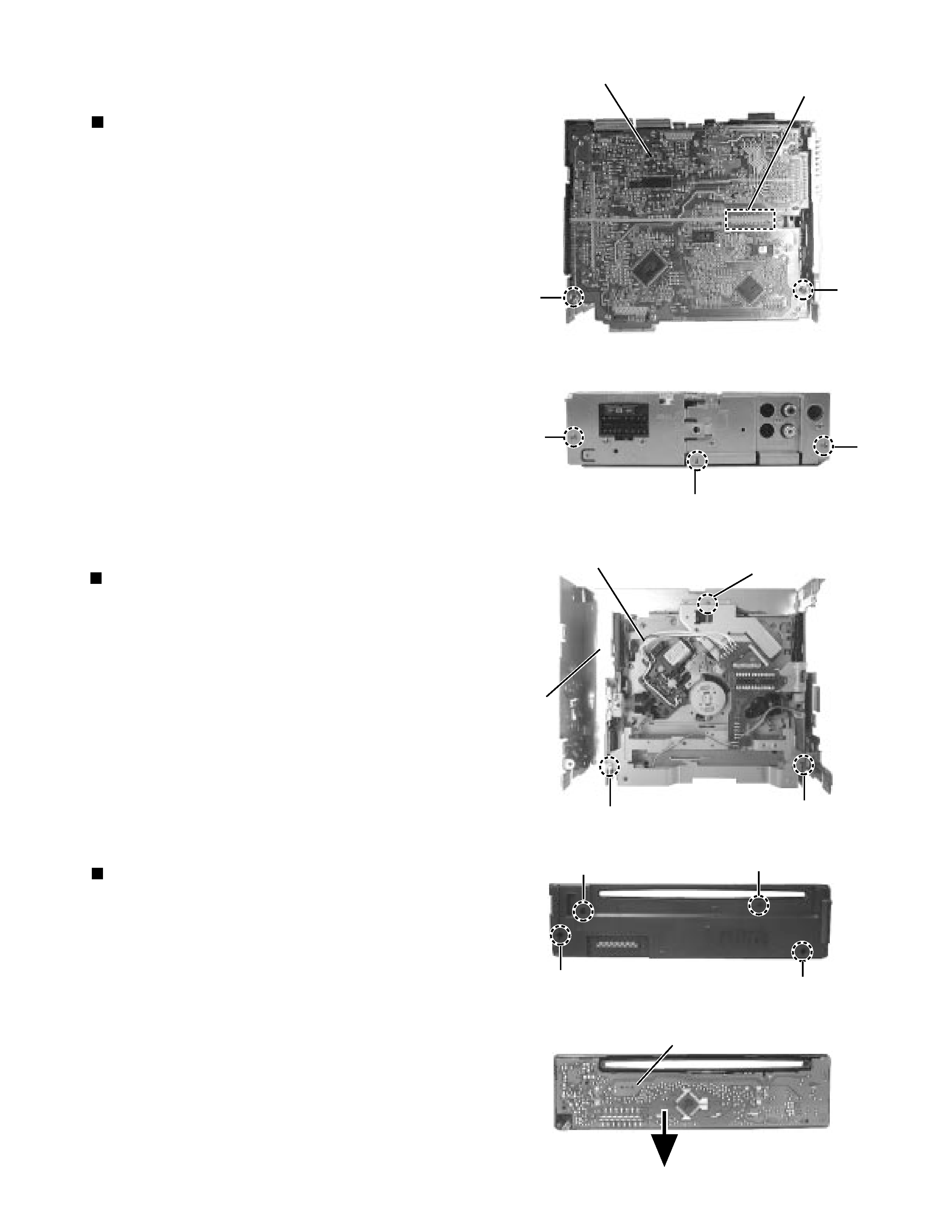
Removing the main amplifier board
(See Fig.5 and 6)
1.
2.
3.
4.
5.
Remove the front chassis.
Remove the bottom cover.
Remove the two screws B attaching the main
amplifier board assembly on the bottom of the body.
Remove the three screws C attaching the main
amplifier board assembly on the back of the body.
Disconnect connector CN501 on the main amplifier
board assembly from the CD mechanism assembly.
Removing the CD mechanism assembly
(See Fig.7)
1.
2.
3.
4.
Remove the front chassis.
Remove the bottom cover.
Remove the main amplifier board assembly.
Remove the three screws D attaching the CD
mechanism assembly from the top cover.
Removing the control switch board
(See Fig.8 and 9)
1.
2.
3.
Remove the front chassis.
Remove the four screws E attaching the rear cover
on the back of the front panel unit.
Remove the control switch board from the front
panel unit.
C
Fig.5
Fig. 6
B
B
C
C
CD mechanism assembly
D
D
D
Top cover
Fig. 7
E
E
E
E
Fig. 8
Fig. 9
Control switch board
CN501
Main amplifier board