SERVICE MANUAL
CD RECEIVER
No.49537
Feb. 2000
COPYRIGHT
2000 VICTOR COMPANY OF JAPAN, LTD.
This service manual is made from 100% recycled paper.
Printed in Japan
200002(O)
VICTOR COMPANY OF JAPAN, LIMITED
MOBILE ELECTRONICS DIVISION,10-1,1Chome,Ohwatari-machi,Maebashi-city,Japan
KD-LX10
KD-LX30
(No.49537)
KD-LX10/KD-LX30
KD-LX10/KD-LX30
Area Suffix
J ---- Nortern America
Contents
Safety precaution
1-2
Instructions
1-3~
Disassembly method
2-1
Adjustment method
2-4
Maintenance of laser pickup
2-14
Replacement of lase pickup
2-14
Extention code connecting method
2-15
Functions of the mechanism under
the servise mode
2-18
Flow of functional until TOC read
2-20
Description of major ICs
2-23
Block diagrams
2-39
Standard schematic diagrams
2-41
Printed circuit board
2-45,46
Parts list
3-1~7
! CAUTION Burrs formed during molding may be left over on some parts of the chassis. Therefore,
pay attention to such burrs in the case of preforming repair of this system.
Safety precaution
! CAUTION Please use enough caution not to see the beam directly or touch it in case of an
adjustment or operation check.
KD-LX10/KD-LX30
2-1
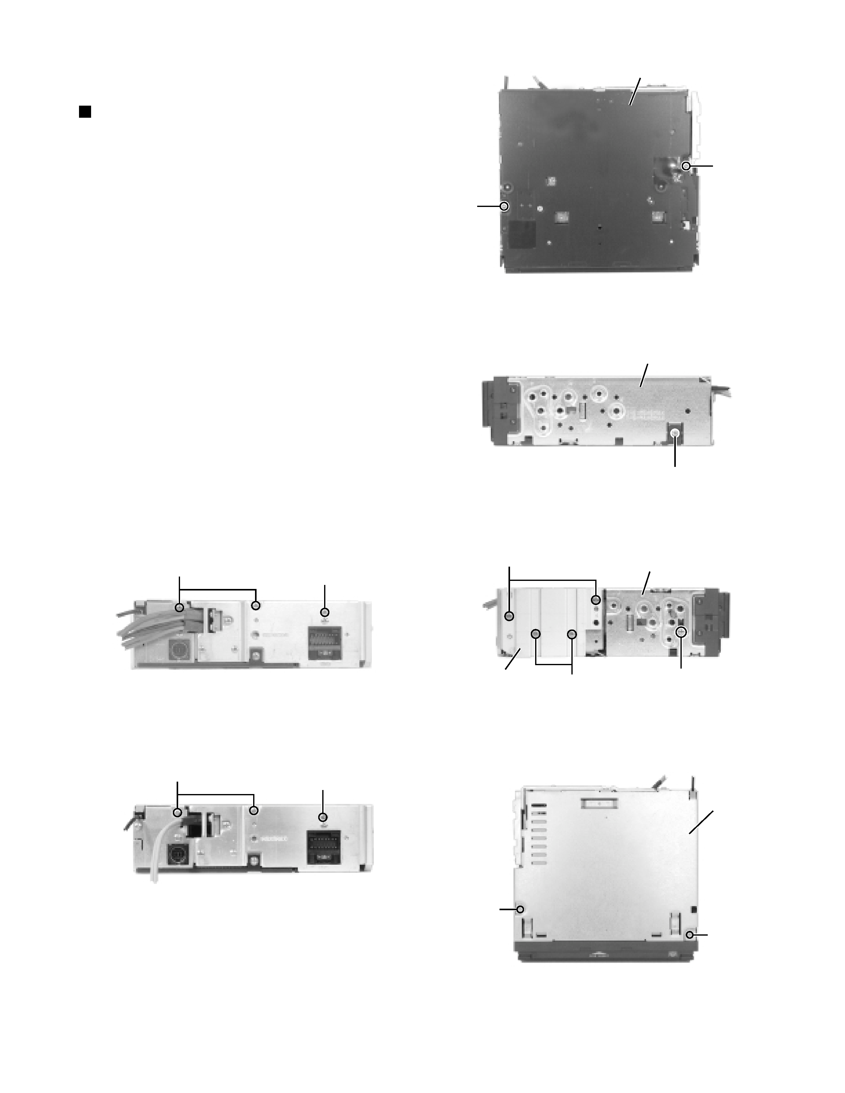
Remove the two screws A
attaching the bottom
cover to the top chassis on the bottom of the body.
Remove the two screws B attaching the top chassis
on both sides of the body.
Remove the two screws C
and the two screw D
attaching the heat sink on the left side of the body.
Remove the two screws E and the screw F on the
back of the body.
Remove the two screws G on the upper side of the
body.
Move the top chassis upward and disconnect the CD
mechanism
connector
from
the
main
board
connector by pulling it. Remove the top chassis from
the body.
1.
2.
3.
4.
5.
6.
Disassembly method
Removing the top chassis
(See Fig.1 to 5)
Fig.1
Fig.2
Fig.3
Fig.4-1 (KD-LX30)
Fig.4-2 (KD-LX10)
Fig.5
Bottom cover
A
A
B
Top chassis
Top chassis
Heat sink
C
D
B
E
F
E
F
Top chassis
G
G
KD-LX10/KD-LX30
2-2
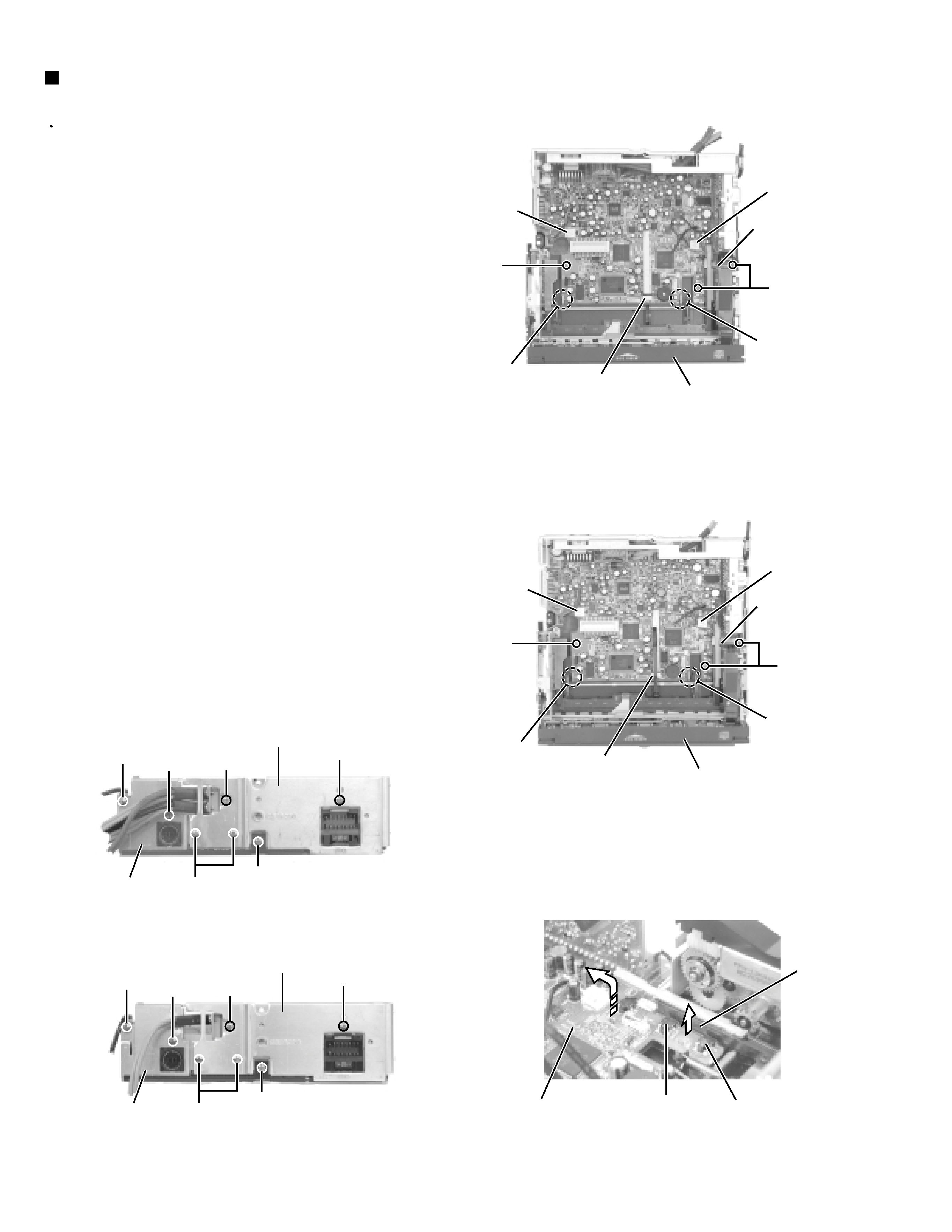
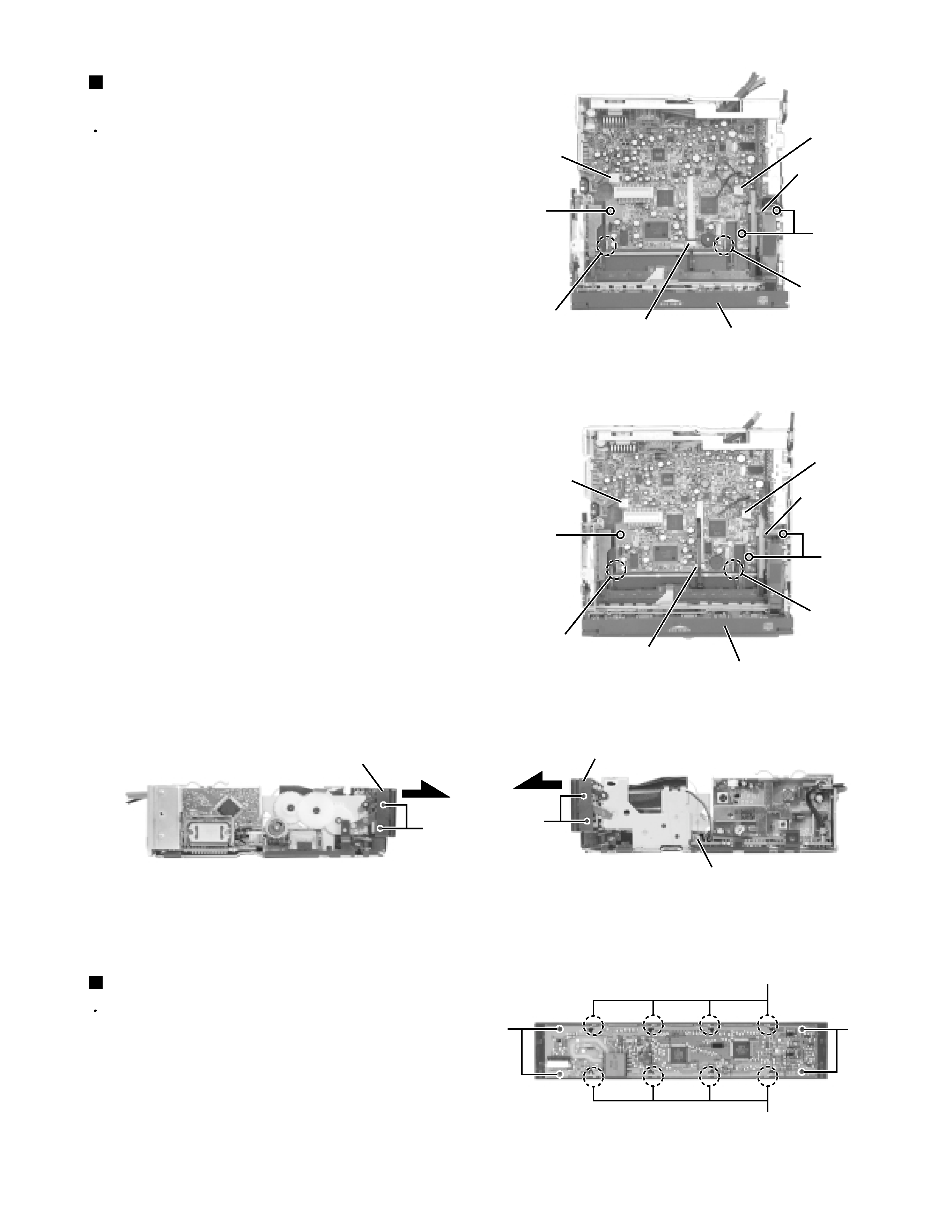
Prior to performing the following procedure, remove
the top chassis.
Disconnect the flexible harness from connector
CN701, the card wire from CN702 on the main board
and
the
harness
from
CN503
and
CN504
respectively.
Remove the three screws H
attaching the main
board assembly to the bottom cover on the upper
side of the body.
Remove the screw I attaching the rear panel and the
bottom cover on the back of the body. Move the
main board in the direction of the arrow and release
the two joints a. (At this point, the main board can be
removed with the rear panel and the rear heat sink.)
Remove the screw J
and the two screws K
attaching the rear heat sink on the back of the body.
Remove the two screws L
and the screw M
attaching the rear panel. Now, the main board
assembly will be removed.
1.
2.
3.
4.
5.
Removing the main board assembly
(See Fig.6 and 7)
when reassembling, correctly engage
the switch S561 and S562 on the main
board
with the part e of the operation
assembly (Refer to Fig.6-3).
ATTENTION:
Fig.6-1 (KD-LX30)
Fig.6-2 (KD-LX10)
Fig.7-1 (KD-LX30)
Fig.7-2 (KD-LX10)
Fig.6-3
H
CN504
CN701
Front panel assembly
CN702
CN503
H
H
CN504
CN701
Front panel assembly
CN702
S652
CN503
H
Main board
S651
J
I
K
L
M
Rear panel
Rear heat sink
L
J
I
K
L
M
Rear panel
Rear heat sink
L
Joint a
Joint a
Joint a
Joint a
e
KD-LX10/KD-LX30
2-3
Prior to performing the following procedure, remove
the top chassis assembly.
Disconnect the flexible harness from connector
CN701 on the main board assembly.
Remove the four screws N attaching the front panel
assembly on both sides of the body. Remove the
front panel toward the front.
1.
2.
Removing the front panel assembly
(See Fig.6,8 and 9)
Prior to performing the following procedure, remove
the top chassis assembly and the front panel
assembly.
Remove the four screws O attaching the front board
on the back of the front panel assembly and release
the eight joints b.
1.
Removing the Front Board (See Fig.10)
Fig.6-1 (KD-LX30)
Fig.6-2 (KD-LX10)
Fig.8
Fig.9
Fig.10
H
CN504
CN701
Front panel assembly
CN702
CN503
H
H
CN504
CN701
Front panel assembly
CN702
CN503
H
CN701
Front panel assembly
N
N
Front panel assembly
O
O
Joints b
Joints b
Joint a
Joint a
Joint a
Joint a