SERVICE MANUAL
CD RECEIVER
No.49732
May. 2002
COPYRIGHT
2002 VICTOR COMPANY OF JAPAN, LTD.
KD-LH1000
KD-LH1000
Area Suffix
J
Northern America
Contents
Safety precaution
Preventing static electricity
Disassembly method
Adjustment method
1-2
1-3
1-4
1-18
Flow of functional
operation unit TOC read
Maintenance of laser pickup
Replacement of laser pickup
Description of major ICs
1-19
1-21
1-21
1-22~41
1000
SOUND
VOL
VOL
SOURCE
R
F
U
D
1-2
KD-LH1000
!
Burrs formed during molding may be left over on some parts of the chassis. Therefore,
pay attention to such burrs in the case of preforming repair of this system.
Safety precaution
!
Please use enough caution not to see the beam directly or touch it in case of an
adjustment or operation check.
1-3
KD-LH1000
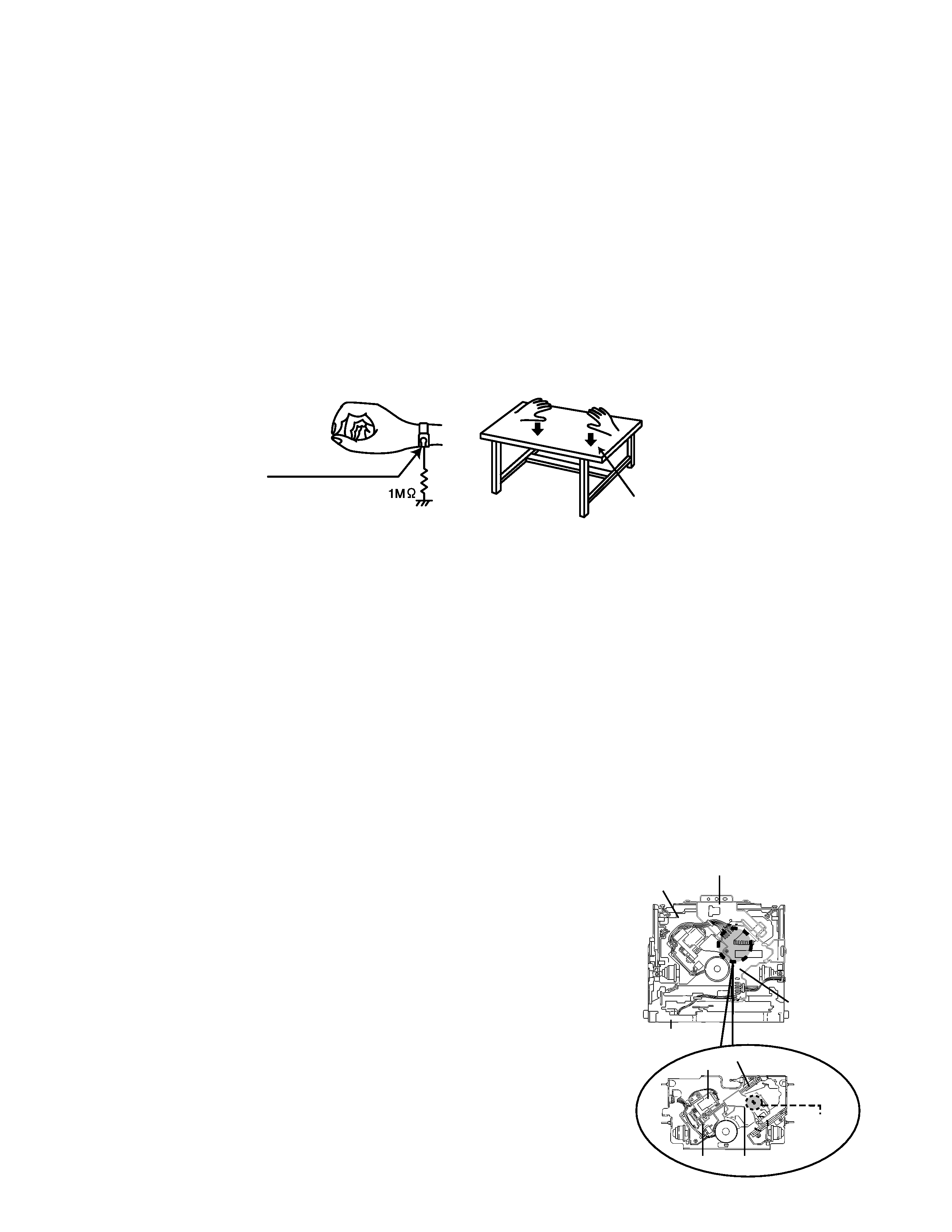
Front bracket
CD mechanism
control board
Damper bracket
CD mechanism ass'y
FD screw
Feed motor ass'y
FD gear
Pickup unit
Preventing static electricity
1.Grounding to prevent damage by static electricity
Electrostatic discharge (ESD), which occurs when static electricity stored in the body, fabric, etc. is discharged,
can destroy the laser diode in the traverse unit (optical pickup). Take care to prevent this when performing repairs.
2.About the earth processing for the destruction prevention by static electricity
Static electricity in the work area can destroy the optical pickup (laser diode) in devices such as CD players.
Be careful to use proper grounding in the area where repairs are being performed.
2-1 Ground the workbench
Ground the workbench by laying conductive material (such as a conductive sheet) or an iron plate over
it before placing the traverse unit (optical pickup) on it.
2-2 Ground yourself
Use an anti-static wrist strap to release any static electricity built up in your body.
3. Handling the optical pickup
1. In order to maintain quality during transport and before installation, both sides of the laser diode on the
replacement optical pickup are shorted. After replacement, return the shorted parts to their original condition.
(Refer to the text.)
2. Do not use a tester to check the condition of the laser diode in the optical pickup. The tester's internal power
source can easily destroy the laser diode.
4.Handling the traverse unit (optical pickup)
1. Do not subject the traverse unit (optical pickup) to strong shocks, as it is a sensitive, complex unit.
2. Cut off the shorted part of the flexible cable using nippers, etc. after replacing the optical pickup. For specific
details, refer to the replacement procedure in the text. Remove the anti-static pin when replacing the traverse
unit. Be careful not to take too long a time when attaching it to the connector.
3. Handle the flexible cable carefully as it may break when subjected to strong force.
4. It is not possible to adjust the semi-fixed resistor that adjusts the laser power. Do not turn it
Soldering
Attention when traverse unit is decomposed
1.Solder is put up before the card wire is removed from connector on
the CD substrate as shown in Figure.
(When the wire is removed without putting up solder, the CD pick-up
assembly might destroy.)
2.Please remove solder after connecting the card wire with
when you install picking up in the substrate.
*Please refer to "Disassembly method" in the text for pick-up and how to
detach the substrate.
(caption)
Anti-static wrist strap
Conductive material
(conductive sheet) or iron plate
1-4
KD-LH1000
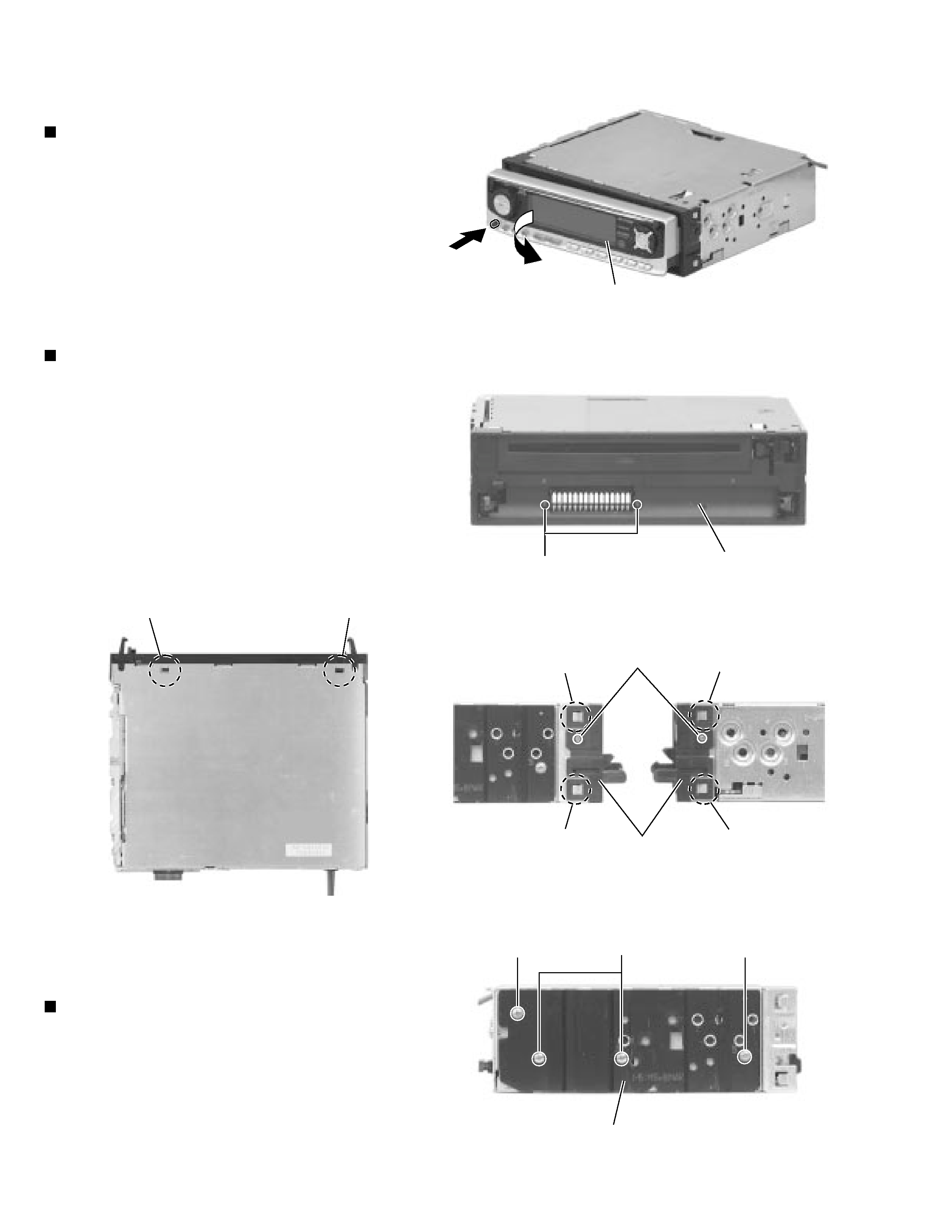
Press the release switch and remove the front panel
unit in the direction of the arrow.
1.
Disassembly method
Removing the front panel unit
(See Fig.1)
Remove the four screws C attaching the heat sink
on the left side of the body, and remove the heat
sink.
1.
Removing the heat sink (See Fig.5)
Remove the two screws A attaching the front
chassis.
Remove the two screws B on each side of the body.
Release the two joints a and the two joints b on the
sides. Release the two joints c at the bottom and
remove the front chassis toward the front.
1.
2.
3.
Removing the front chassis
(See Fig.2 to 4)
Joint c
Heat sink
Fig.2
Fig.1
Fig. 3
Fig.4
Fig. 5
Front panel unit
Front chassis
A
Front chassis
Joint a
Joint a
Joint b
Joint b
C
C
C
Joint c
B
1-5
KD-LH1000
Prior to performing the following procedure, remove
the front chassis and the heat sink.
Turn the body upside down.
Insert a screwdriver to the two joints d and two joints
e on both sides of the body and the joint f on the
back of the body, then detach the bottom cover from
the body.
1.
2.
Removing the bottom cover (See Fig.6)
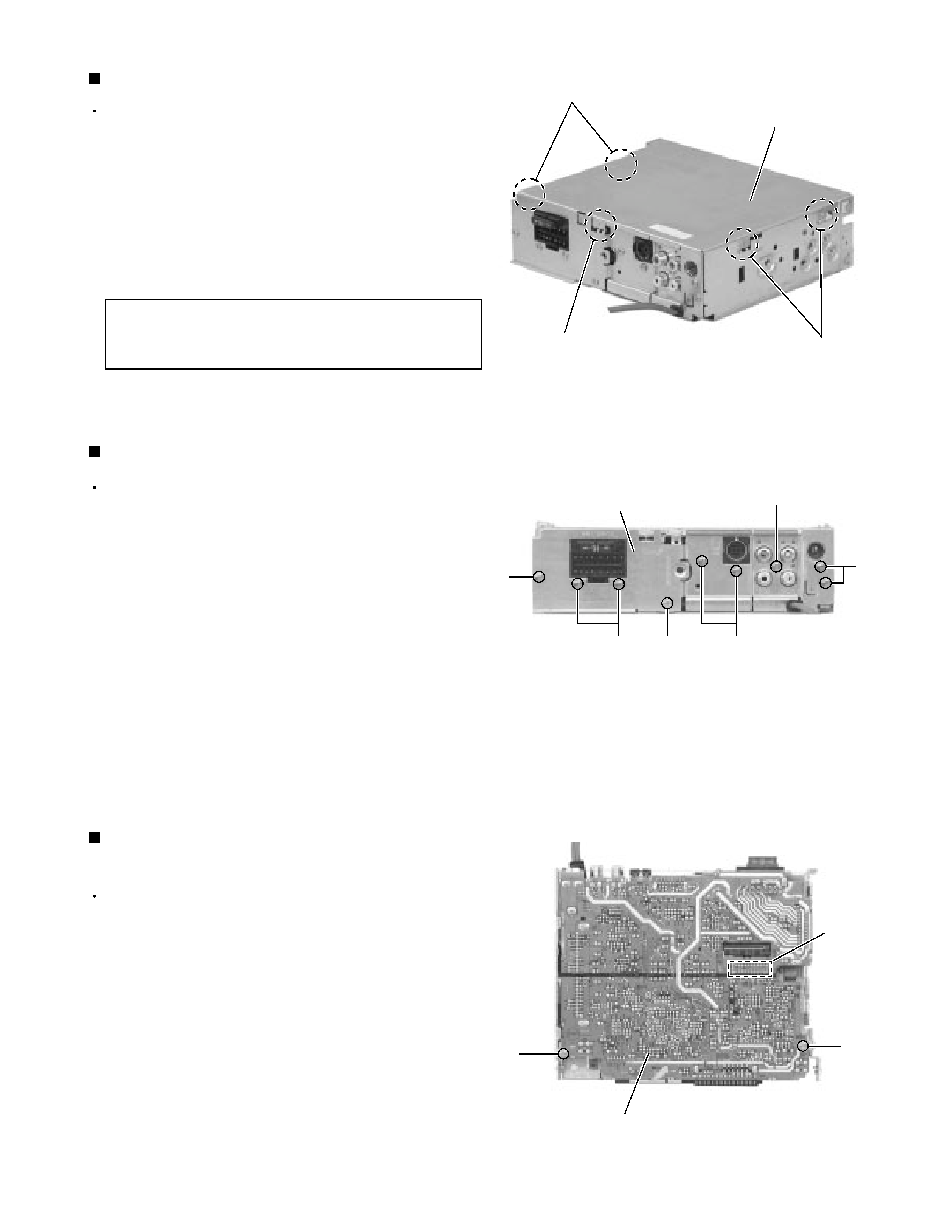
Prior to performing the following procedure, remove
the front chassis, the heat sink and bottom cover.
Remove the eight screws D attaching the rear panel
and one screw E attaching the pine jack on the back
of the body.
1.
Removing the rear panel (See Fig.7 )
Prior to performing the following procedure, remove
the front chassis, the heat sink, bottom cover and the
rear panel.
Remove the two screws F
attaching the main
amplifier board assembly on the top cover.
Disconnect connector CN601 on the main amplifier
board assembly from the cassette mechanism
assembly.
1.
2.
Removing the main amplifier board assembly
(See Fig.8)
When disengaging the joint f using a
screwdriver, do not damage or break the
board.
CAUTION:
Bottom cover
Fig. 6
Fig. 7
Fig. 8
Main board assembly
Joints d
Joints e
Joint f
D
D
D
D
D
E
Rear panel
CN601
F
F