SERVICE MANUAL
DIGITAL VIDEO CAMERA
No. 86644
May 2001
This service manual is printed on 100% recycled paper.
COPYRIGHT © 2001 VICTOR COMPANY OF JAPAN, LTD.
GR-DVM55KR,DVM75KR
Regarding service information other than these sections, refer to the GR-DVM55U/DVM75U service manual (No. 86615).
Also, be sure to note important safety precautions provided in the service manual.
SPECIFICATIONS (The specifications shown pertain specifically to the model GR-DVM55U/DVM75U)
Camcorder
For General
Power supply
: DC 11.0 V } (Using AC Adapter)
DC 7.2 V } (Using battery pack)
Power consumption
LCD monitor off, viewfinder on
: Approx. 4.4 W (GR-DVM75), Approx. 4.0 W (GR-DVM55)
LCD monitor on, viewfinder off
: Approx. 5.2 W (GR-DVM75), Approx. 4.8 W (GR-DVM55)
Dimensions (W x H x D)
: 97 mm x 120 mm x 51 mm (3-7/8" x 4-3/4" x 2-1/16")
(with the LCD monitor closed and the viewfinder pushed back in)
Weight
: Approx. 500 g (1.1 lbs) (GR-DVM75)
Approx. 470 g (1.1 lbs) (GR-DVM55)
Operating temperature
: 0°C to 40°C (32°F to 104°F)
Operating humidity
: 35% to 80%
Storage temperature
: 20°C to 50°C (4°F to 122°F)
Pickup
: 1/4" CCD
Lens
: F 1.8, f = 3.6 mm to 36 mm, 10:1 power zoom lens
Filter diameter
: ø27 mm
LCD monitor
: 2.5" diagonally measured, LCD panel/TFT active matrix system
Viewfinder
: Electronic viewfinder with 0.44" colour LCD
Speaker
: Monaural
For Digital Video Camera
Format
: DV format (SD mode)
Signal format
: NTSC standard
Recording/Playback format
: Video: Digital component recording
: Audio: PCM digital recording, 32 kHz 4-channel (12-bit),
48 kHz 2-channel (16-bit)
Cassette
: Mini DV cassette
Tape speed
: SP: 18.8 mm/s
LP: 12.5 mm/s
Maximum recording time
: SP: 80 min.
(using 80 min. cassette)
LP: 120 min.
For Digital Still Camera (GR-DVM75 only)
Storage media
: SD Memroy Card/MultiMediaCard
Compression system
: Still image : JPEG (compatible)
Moving image : MPEG4 (compatible)
File size
: 2 modes (XGA: 1024 x 768 pixels/VGA: 640 x 480 pixels)
Picture quality
: 2 modes (FINE/STANDARD)
Approximate number of storable images
(with the provided memory card [8 MB], with Sound Effects pre-stored)
FINE
: 40 (VGA), 20 (XGA)
STANDARD
: 130 (VGA), 60 (XGA)
(with an optional memory card [16 MB])
FINE
: 100 (VGA), 40 (XGA)
STANDARD
: 290 (VGA), 140 (XGA)
(with an optional memory card [32 MB])
FINE
: 210 (VGA), 90 (XGA)
STANDARD
: 610 (VGA), 290 (XGA)
(with an optional memory card [64 MB])
FINE
: 430 (VGA), 190 (XGA)
STANDARD
: 1230 (VGA), 600 (XGA)
For Connectors
AV
Video output
: 1 V (p-p), 75
, analog
Video input (GR-DVM75 only)
: 0.8 V (p-p) 1.2 V (p-p), 75
, analog
Audio output
: 300 mV (rms), 1 k
, analog, stereo
Audio input (GR-DVM75 only)
: 300 mV (rms), 50 k
, analog, stereo
Headphone output (GR-DVM75 only) : Stereo
DV
Input/output
: 4-pin, IEEE 1394 compliant
AC adapter AP-V10U
Power requirement
U.S.A. and Canada
: AC 120 V`, 60 Hz
Other countries
: AC 110 V to 240 V`, 50 Hz/60 Hz
Output
: DC 11 V }, 1 A
Dimensions (W x H x D)
: 59 mm x 31 mm x 84 mm (2-3/8" x 1-1/4" x 3-5/16")
Weight
: Approx. 130 g (0.29 lbs)
Jack Box
For General
Dimensions (W x H x D)
: 52 mm x 22 mm x 73 mm (2-1/16" x 7/8" x 2-7/8")
Weight
: Approx. 35 g (0.78 lbs)
For Connectors
USB (GR-DVM75 only)
: Type B
EDIT (GR-DVM75 only)
: ø3.5 mm, 2-pole
S-Video
Output
: Y : 1 V (p-p), 75
, analog
C : 0.29 V (p-p), 75
, analog
Input (GR-DVM75 only)
: Y : 0.8 V (p-p) 1.2 V (p-p), 75
, analog
C : 0.2 V (p-p) 0.4 V (p-p), 75
, analog
JLIP (GR-DVM55 only)
: ø3.5 mm, 4-pole
PC (DIGITAL PHOTO)
(GR-DVM55 only)
: ø2.5 mm, 3-pole
Specifications shown are for SP mode unless otherwise indicated. E & O.E. Design and specifications subject
to change without notice.
!
REF.
MODEL
GR-DVM55U
GR-DVM55KR
GR-DVM75U
GR-DVM75KR
NO.
ITEM
PW
MAIN BOARD ASSY
YB10318A-01
* YB10318A-02
YB10319A-01
* YB10319A-02
C3050
CAPACITOR
--
* NCBA1CK-103W
--
* NCBA1CK-103W
SD3
SHIELD SHEET
--
* LY43181-001A
--
* LY43181-001A
OT7
SPACER(A)
--
* LY30029-0Q4A
--
* LY30029-0Q3A
OT8
SPACER(A)
--
--
--
* LY30029-0Q1A
TABLE OF CONTENTS
DIFFERENT TABLE .................................................................................................................................................................. 1
4. CHARTS AND DIAGRAMS (4-1 to 4-12)
4.1
MAIN CIRCUIT BOARD [GR-DVM55KR] ..................................................................................................................... 4-1
4.2
MAIN CIRCUIT BOARD [GR-DVM75KR] ..................................................................................................................... 4-7
5. PARTS LIST (5-1 to 5-5)
5.1
PACKING AND ACCESSORY ASSEMBLY <M1> ........................................................................................................ 5-1
5.2
FINAL ASSEMBLY <M2> ............................................................................................................................................. 5-3
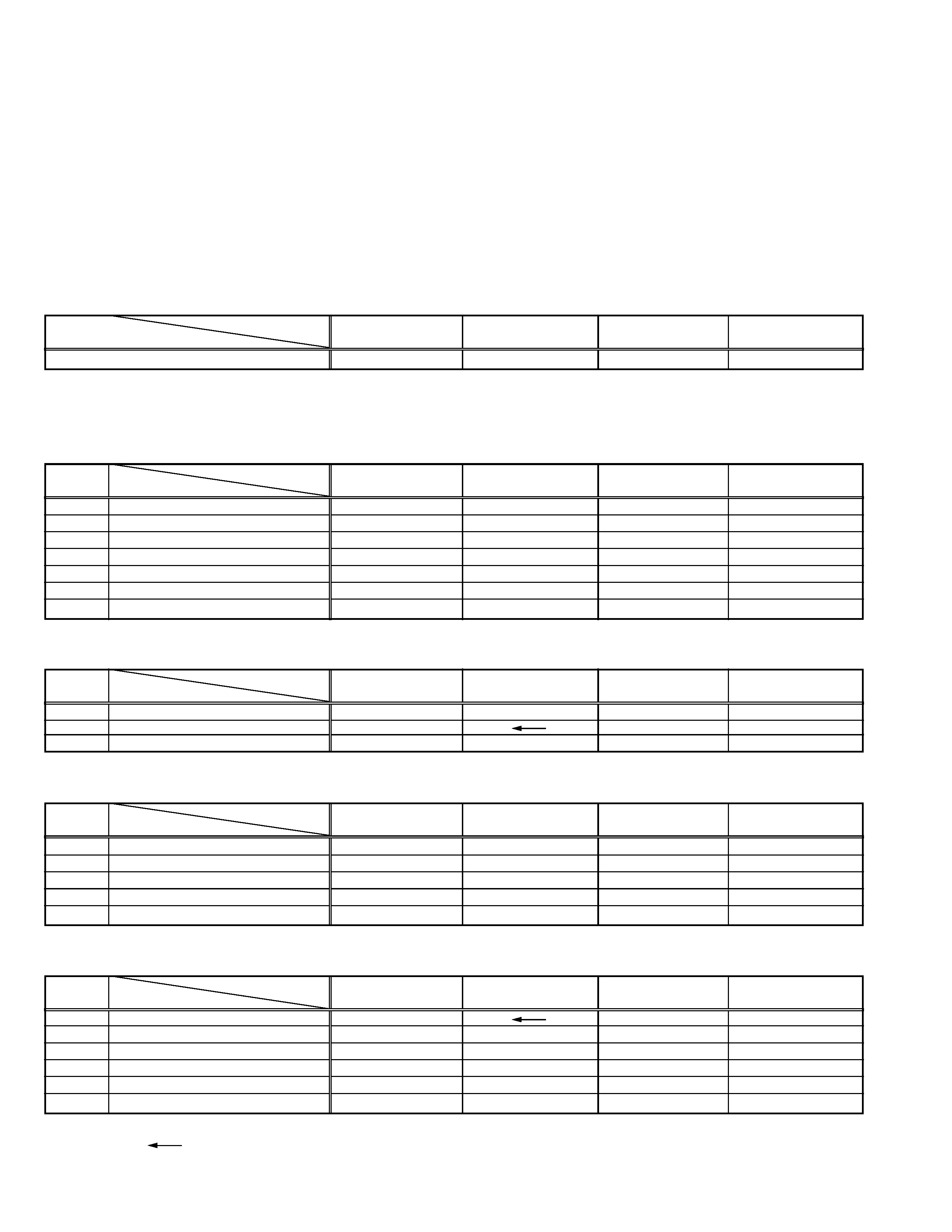
The following table indicate different parts number between models GR-DVM55U, GR-DVM55KR, GR-DVM75U and GR-DVM75KR.
PACKING AND ACCESSORY ASSEMBLY <M1> Note: As for IB (INSTRUCTIONS), refer to sec.5.
1
The following table indicate main different points between models GR-DVM55U, GR-DVM55KR, GR-DVM75U and GR-DVM75KR.
!
REF.
MODEL
GR-DVM55U
GR-DVM55KR
GR-DVM75U
GR-DVM75KR
NO.
ITEM
8
Q.CARD(JCA)
YU10350
--
YU10350
--
9
WARRANTY INF.
BT-51005-4
--
BT-51005-4
--
10
REGIST.CARD
BT-51020-2
--
BT-51020-2
--
! 12
AC ADAPTER
LY20739-001A
LY20688-010A
LY20739-001A
LY20688-010A
24
CORE FILTER
QQR0491-002
QQR0490-002
--
QQR0490-002
! 28
POWER CORD
--
QMPS130-190-JC
--
QMPS130-190-JC
29
WARRANTY CARD
--
--
--
BT-56010-1
FINAL ASSEMBLY <M2>
!
REF.
MODEL
GR-DVM55U
GR-DVM55KR
GR-DVM75U
GR-DVM75KR
NO.
ITEM
188
LABEL(EMC)
--
LY43226-002A
--
LY43226-001A
229
SCREW
QYSPSGT1735Z
QYSPSGT1735Z
* QYSPSGT1730Z
231
SCREW
--
--
QYSPSGT1735Z
* QYSPSGT1730Z
MAIN BOARD ASSEMBLY <01>
JACK BOARD ASSEMBLY <09>
!
REF.
MODEL
GR-DVM55U
GR-DVM55KR
GR-DVM75U
GR-DVM75KR
NO.
ITEM
PW1
JACK BOARD ASSY
YB10323A1
YB10323A1
YB10323B1
Q2801
TRANSISTOR
--
--
--
2SD1979/S/-X
R2801
MG RESISTOR
--
--
--
NRSA63J-103X
R2805
MG RESISTOR
--
--
--
NRSA63J-0R0X
C2801
CAPACITOR
--
--
--
NCB31CK-683X
C2803
CAPACITOR
--
--
--
NCB31EK-153X
Notes : Mark
is same as left.
Mark -- is not used.
Mark* reference model was also changed.
.
MODEL
GR-DVM55U
GR-DVM55KR
GR-DVM75U
GR-DVM75KR
ITEM
AC ADAPTER
AP-V10U
AP-V10KR
AP-V10U
AP-V10KR

Printed in Japan
S40894

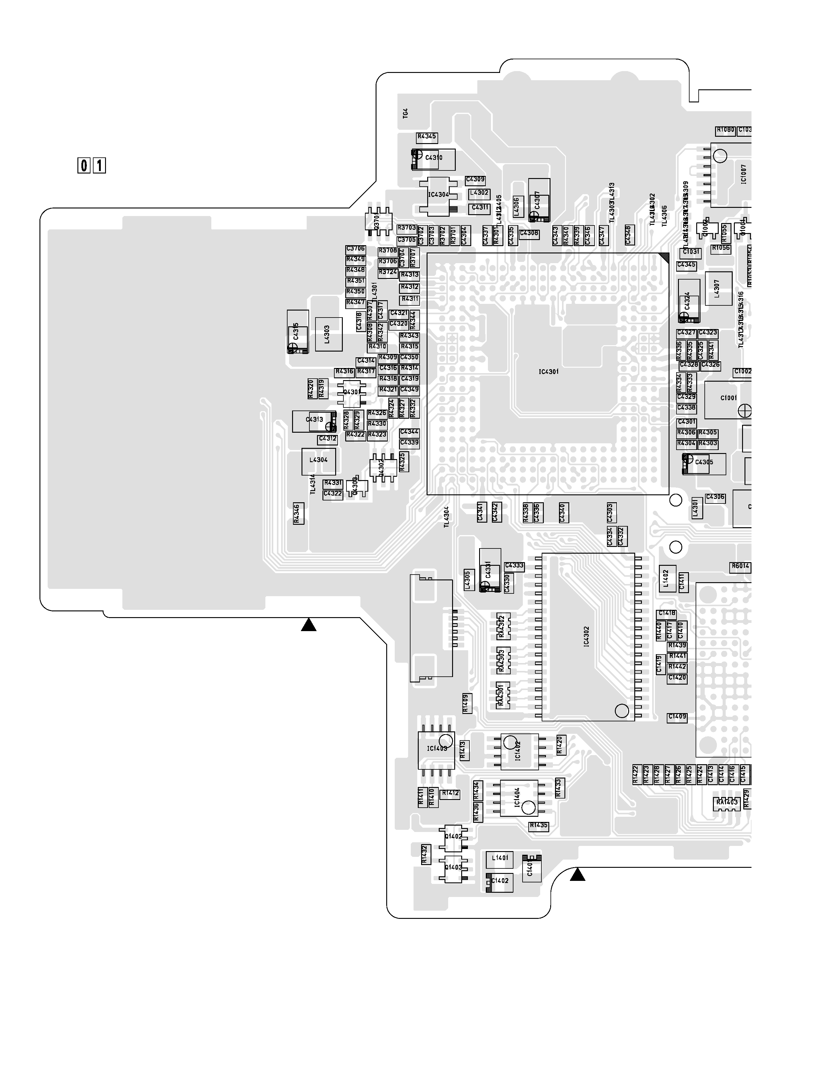
SECTION 4
CHARTS AND DIAGRAM
3
2
CN111
1
YB10318-01-02
MAIN PWB
FOIL SIDE(B)
8
5
19
1
20
1
8
4
5
4
8
5
1
38
1
4
6
1
71
1
5
3
4
4.1
MAIN CIRCUIT BOARD [GR-DVM55KR]
4-1