
SERVICE MANUAL
No.86588
October 2000
GC-QX3HDU/GC-QX5HDU
DIGITAL STILL CAMERA
SPECIFICATIONS
STILL CAMERA
Power source
Power consumption
Dimensions
Weight
Operating temperature
Relative humidity
Storage temperature
LCD screen
Storage media
CCD
Focal distance
Lens
Video
Recording format
Sensitivity
Iris value (F value)
Exposure control
Exposure compensation
Minimum subject distance
Light measurement system
Flash
Recommended distance for flash
Shutter speed
White balance
Focus
: DC 5 V
: 3.6 W (when the LCD screen is off)
4.8 W (when the LCD screen is on)
: 111 (W) mm x 67 (H) mm x 59 (D) mm
(4-3/8" x 2-11/16" x 2-3/8") (except protruding parts)
: Approx. 290 g (0.64 lbs)
(without a Memory card and battery)
:0
°C to 40°C (32°F to 104°F)
: 35% to 80%
: 20
°C to 50°C (4°F to 122°F)
: 2.0 inch, polysilicon TFT (200,000 pixels)
: SmartMediaTM 3.3V (up to 64MB)
: 3.34 million pixels (3.24 million valid pixels),
1/1.8" square pixels, primary color filter,
interlace scan CCD
: 7.5 mm to 17.5 mm
(equivalent to 37mm to 86 mm on a 35 mm still camera)
: 2.3X optical zoom lens
: 160 pixels x 120 pixels, 20 seconds, JVC original format
: Exif Ver. 2.1 (DCF compliant), TIFF (Uncompressed),
DPOF-compatible
: 80/160/320 (ISO compliant)
: F2.8/3.8, 5.6, 8, 11
: Program AE, iris priority AE
:
±2EV (0.5EV steps)
: Approx. 2 cm to 50 cm (in Macro mode)
: Multi, spot
: Built-in,
Auto/red-eye prevention/forced/disabled
: Approx. 2.5 m
: Auto (Program AE: 1/8 seconds 1/750 seconds,
Iris priority AE: 2 seconds 1/750 seconds )
: Auto/Manual ( ,
,
, MWB,
)
: Auto/Manual
Self timer
Photo quality
Number of storable photos
(with an 8MB Memory card,
STANDARD/FINE/NO COMP.)
Battery
Printer connector
VIDEO output connector
Digital output connector
: 1 second, 8 seconds
: 3 modes (STANDARD/FINE/NO COMP.)
: 2032 x 1536: approx. 10/8/0
1024 x 768: approx. 43/32/3
640 x 480: approx. 87/65/8
: Lithium ion battery
: Output for optional printer
: Two-pole plug, 3.5 mm diameter (NTSC)
: Mini-USB connector
AC Power Adapter/Charger AA-V37
E. & O. E. Design and specifications subject to change without notice.
: AC 120 V`, 60 Hz
: AC 110 V 240 V`, 50 Hz/60 Hz
: 14 W
: DC 3.6 V
, 0.77 A
: DC 5.0 V
, 1.5 A
:0
°C to 40°C (32°F to 104°F)
[when charging: 10
°C to 35°C (50°F to 95°F)]
: 68 (W) mm x 38 (H) mm x 110 (D) mm
(2-11/16" x 1-1/2" x 4-3/8")
: Approx. 230 g (0.51 lbs) (without a DC cord)
Power requirement
U.S.A. and Canada
Other countries
Power consumption
Output
Charge
Camera
Operating temperature
Dimensions
Weight
Regarding service information other than these sections, refer to the GC-QX3U service manual (No.86564).
Also, be sure to note important safety precautions provided in the service manual.

TABLE OF CONTENTS
Section
Title
Page
I
mportant Safety Precautions
DIFFERENT TABLE
1. DISASSEMBLY
1.3.2 Disassembly method ( I ) ............................................ 1-1
2. ELECTRICAL ADJUSTMENT
2.1
ELECTRICAL ADJUSTMENT .......................................... 2-1
2.1.1 Precautions ................................................................. 2-1
2.1.2 Test instruments required for electrical adjustment ............. 2-1
2.1.3 Required test equipment ............................................ 2-1
2.1.4 Setup (LCD ADJUSTMENT) ........................................ 2-1
2.1.5 Setup (CCD ADJUSTMENT) ....................................... 2-2
2.2
Setup with patch cords and jig connector cables ............ 2-3
3. CHARTS AND DIAGRAMS
NOTES OF SCHEMATIC DIAGRAM ........................................ 3-1
CIRCUIT BOARD NOTES ......................................................... 3-2
3.1
BOARD INTERCONNECTION ......................................... 3-3
3.2
MAIN (SYSCON) SCHEMATIC DIAGRAM ...................... 3-5
3.3
MAIN (DSP146) SCHEMATIC DIAGRAM ........................ 3-7
3.4
MAIN (DSP97) SCHEMATIC DIAGRAM .......................... 3-9
3.5
MAIN (CDS AGC A/D AND ARM ROM)
SCHEMATIC DIAGRAM ................... 3-11
3.6
MAIN (STROBE CONTROL AND AUDIO ) AND
STROBE FLASH SCHEMATIC DIAGRAMS ........ 3-12
3.7
MAIN (F/Z_MDA / IRIS) SCHEMATIC DIAGRAM ......... 3-13
3.8
JACK (VIDEO OUT/USB/PRINTER/DC JACK/
MONITOR BACK LIGHT) SCHEMATIC DIAGRAM .... 3-14
3.9
CCD SCHEMATIC DIAGRAM ........................................ 3-15
3.10 MONI REG (MONITOR) SCHEMATIC DIAGRAM ......... 3-16
3.11 MONITOR REG (DC/DC) SCHEMATIC DIAGRAM ........ 3-17
3.12 MAIN CIRCUIT BOARD (YB10299-01-01) ..................... 3-19
3.13 MAIN CIRCUIT BOARD (YB10299-01-03) ..................... 3-25
3.14 MONITOR REG CIRCUIT BOARD (YB10300-01-01) ..... 3-31
3.15 MONITOR REG CIRCUIT BOARD (YB10300-01-02) ..... 3-31
3.16 JACK CIRCUIT BOARD (YB10300-01-01) .................... 3-35
3.17 JACK CIRCUIT BOARD (YB10300-01-02) .................... 3-37
3.18 CCD CIRCUIT BOARD (YB10300-01-01) ...................... 3-39
3.19 CCD CIRCUIT BOARD (YB10300-01-02) ...................... 3-40
3.20 STOROBE FLASH CIRCUIT BOARD (YB10300-01-01) ... 3-41
3.21 STOROBE FLASH CIRCUIT BOARD (YB10300-01-02) ... 3-42
3.22 OVER ALL BLOCK DIAGRAM ....................................... 3-43
4. PARTS LIST
4.1
PACKING AND ACCESSORY ASSEMBLY <M1> ........... 4-1
4.3
FINAL ASSEMBLY <M2> .............................................. 4-3
4.4
ELECTRICAL PARTS LIST ............................................... 4-6
MAlN BOARD ASSEMBLY <01> .................................... 4-6
CCD BOARD ASSEMBLY <02> .................................... 4-11
MONI REG BOARD ASSEMBLY <03> ......................... 4-12
JACK BOARD ASSEMBLY <04> .................................. 4-14
STROBE FLASH BOARD ASSEMBLY <05> ................. 4-15
The following table indicate main different features between models GC-QX3U, GC-QX3HDU and GC-QX5HDU.
Shooting Continuous Photos
YES
NO
YES
Collage Mode
YES
NO
YES
6M Pro-Still(Pixel Shift Mode)
YES
NO
YES
DR Pro-Still(Wide Range Mode)
YES
NO
YES
Installing the Film Copying Adapter
NO
NO
YES
Shooting Film(Film Copy Mode)
NO
NO
YES
MODEL
GC-QX3U
GC-QX3HDU
ITEM
GC-QX5HDU
Operating Environment
The host computer that runs the Macintosh®
operating environment must satisfy the following
conditions.
USB Driver
1. USB-compatible computer (iMacTM, iBookTM,
Power MacTM G3/G4, Power BookTM G3, etc.)
2. Mac OS 8.5.1/Mac OS 8.6/Mac OS 9.0
JVC Video Decoder
1. Power PC 603e/120MHz or faster
2. Mac OS 7.6.1 or later
3. QuickTime 3.0 or later
4. Minimum RAM requirement: 32MB
5. Minimum hard disk space requirement: 1MB
* Macintosh® is a registered trademark of Apple
Computer.
* Other trademarks are property of their respective
owners.
* If you use Macintosh® which does not have a USB
port, use an optional flash path, conversion card
adapter, etc. For details on the operating environ-
ment of these devices, contact the dealers or
manufacturers.
SOFTW ARE SECTION FOR Macintosh
®
Operating Environment
SOFTW ARE SECTION FOR Windows
®
The host computer that runs the Windows®
operating environment must satisfy the following
conditions.
USB Driver
1. Microsoft® Windows® 98/Windows® 98 Second
Edition, Full version (Not Upgrade)/Windows®
2000 Professional (Not Upgrade)
2. Available USB port
3. CD-ROM drive
Video Player
1. CPU: Intel® Pentium® 200MHz class or higher
2. Microsoft® Windows® 95/Windows® 98
3. Display capability of 65,536 colors or more
4. CD-ROM drive
5. Minimum RAM requirement: 32MB
6. Minimum hard disk space requirement: 1MB
* The system requirements information is not a
guarantee that provided software applications will
work on all personal computers meeting those
requirements.
* Microsoft®, Windows® are either registered
trademarks or trademarks of Microsoft corporation
in United States and/or other countries.
* Intel®, Pentium® are registered trademarks of Intel
corporation.
* Other trademarks are property of their respective
owners.
* If you use Windows® 95 or a personal computer
which does not have a USB port, use an optional
flash path, conversion card adapter, etc. For
details on the operating environment of these
devices, contact the dealers or manufacturers.
Note : Mark is not used.
The following table indicate different parts number between models GC-QX3U, GC-QX3HDU and GC-QX5HDU.
1
PACKING CASE
LY31465-002A
LY31465-013A
LY32048-002A
2
POLY BAG
LY30023-016A
LY30023-016A
+
3
CUSHION
LY31466-001A
LY31466-001A
+
4
SHEET
LY42548-001A
5
HOOD(OP)
LY31822-001A
5A
POLY BAG
QPA01001505
9
CD-ROM ASSEMBLY
LY31074-007A
LY31133-018A
+
13
FILM COPY ADAP.
LY20687-001A
14
FILM HOLDER AS
LY32047-001A
15
CUSHION(ACC)
LY32050-001A
19
CABLE ASSY(AUDIO/VIDEO)
QAM0297-001
+
20
POLY BAG
QPA01202505
+
27
MEDIA CARD ASSY
LY31737-001A
+
LY31737-002A
! 31
INST.BOOK(EN)
LYT0543-001C
LYT0668-001C
LYT0668-001A
! 32
INST.BOOK(FR)
LYT0543-002A
LYT0668-002C
LYT0668-002A
! 33
INST.BOOK(SP)
LYT0543-003A
LYT0668-003C
LYT0668-003A
MODEL
GC-QX3U
ITEM
PACKING ASSEMBLY <M1>
REF NO.
GC-QX3HDU
GC-QX5HDU
Note : Mark is not used.
103
BOARD HOLDER ASSEMBLY
LY31457-002A
+
LY31457-007B
107C
SHEET
LY42322-001A
110
TOP COVER ASSEMBLY
LY31460-003A
LY31460-009A
LY31460-008B
111
OPERATION UNIT
LY20521-002C
LY20521-002D
LY20521-007B
113
SPACER(A)
LY30029-016A
118
MICROPHONE
LY31454-001A
+
125
S.SHEET(FFC)
LY42506-001A
130
SHEET
LY42890-001A
+
131
SPACER(A)
LY30029-0C2A
+
152
REAR COVER ASSEMBLY
LY20519-003B
LY20519-009A
LY20519-010A
153
FRONT COVER ASSEMBLY
LYH20147-001A
LYH20222-003A
LYH20222-002A
153A
FRONT COVER
LY20516-003A
LY20516-009A
LY20516-008A
153B
GRIP
LY42320-001A
LY31444-001A
+
MODEL
GC-QX3U
ITEM
FINAL ASSEMBLY <M1>
REF NO.
GC-QX3HDU
GC-QX5HDU
203
OPTICAL BLOCK ASSEMBLY
LY31490-001B
LY31490-004A
+
221
TILT FRAME
*LY20716-001A
++
MODEL
GC-QX3U
ITEM
OP BLOCK ASSEMBLY <M3>
REF NO.
GC-QX3HDU
GC-QX5HDU
Note : Mark is not used.
Note : Mark * is GC-QX3U was also changed.
PW1
MAIN BOARD ASSEMBLY
YB10282B-06
YB10299K-03
YB10299U-01
MODEL
GC-QX3U
ITEM
MAIN BOARD ASSEMBLY <01>
REF NO.
GC-QX3HDU
GC-QX5HDU
PW1
CCD BOARD ASSEMBLY
YB10283A1-04
YB10300K1-02
YB10300U1-01
MODEL
GC-QX3U
ITEM
CCD BOARD ASSEMBLY <02>
REF NO.
GC-QX3HDU
GC-QX5HDU
PW4
MONI REG BOARD ASSEMBLY
YB10283A4-04
YB10300K4-02
YB10300U4-01
MODEL
GC-QX3U
ITEM
MONI REG BOARD ASSEMBLY <03>
REF NO.
GC-QX3HDU
GC-QX5HDU
PW2
JACK BOARD ASSEMBLY
YB10283A2-04
YB10300K2-02
YB10300U2-01
MODEL
GC-QX3U
ITEM
JACK BOARD ASSEMBLY <04>
REF NO.
GC-QX3HDU
GC-QX5HDU
PW3
STROBE BOARD ASSEMBLY
YB10283A3-04
YB10300K3-02
YB10300U3-01
MODEL
GC-QX3U
ITEM
STROBE BOARD ASSEMBLY <05>
REF NO.
GC-QX3HDU
GC-QX5HDU
Important Safety Precautions
Prior to shipment from the factory, JVC products are strictly inspected to conform with the recognized product safety and electrical codes
of the countries in which they are to be sold. However, in order to maintain such compliance, it is equally important to implement the
following precautions when a set is being serviced.
Fig.1
1. Locations requiring special caution are denoted by labels and
inscriptions on the cabinet, chassis and certain parts of the
product. When performing service, be sure to read and com-
ply with these and other cautionary notices appearing in the
operation and service manuals.
2. Parts identified by the
symbol and shaded (
) parts are
critical for safety.
Replace only with specified part numbers.
Note: Parts in this category also include those specified to com-
ply with X-ray emission standards for products using
cathode ray tubes and those specified for compliance
with various regulations regarding spurious radiation
emission.
3. Fuse replacement caution notice.
Caution for continued protection against fire hazard.
Replace only with same type and rated fuse(s) as specified.
4. Use specified internal wiring. Note especially:
1) Wires covered with PVC tubing
2) Double insulated wires
3) High voltage leads
5. Use specified insulating materials for hazardous live parts.
Note especially:
1) Insulation Tape
3) Spacers
5) Barrier
2) PVC tubing
4) Insulation sheets for transistors
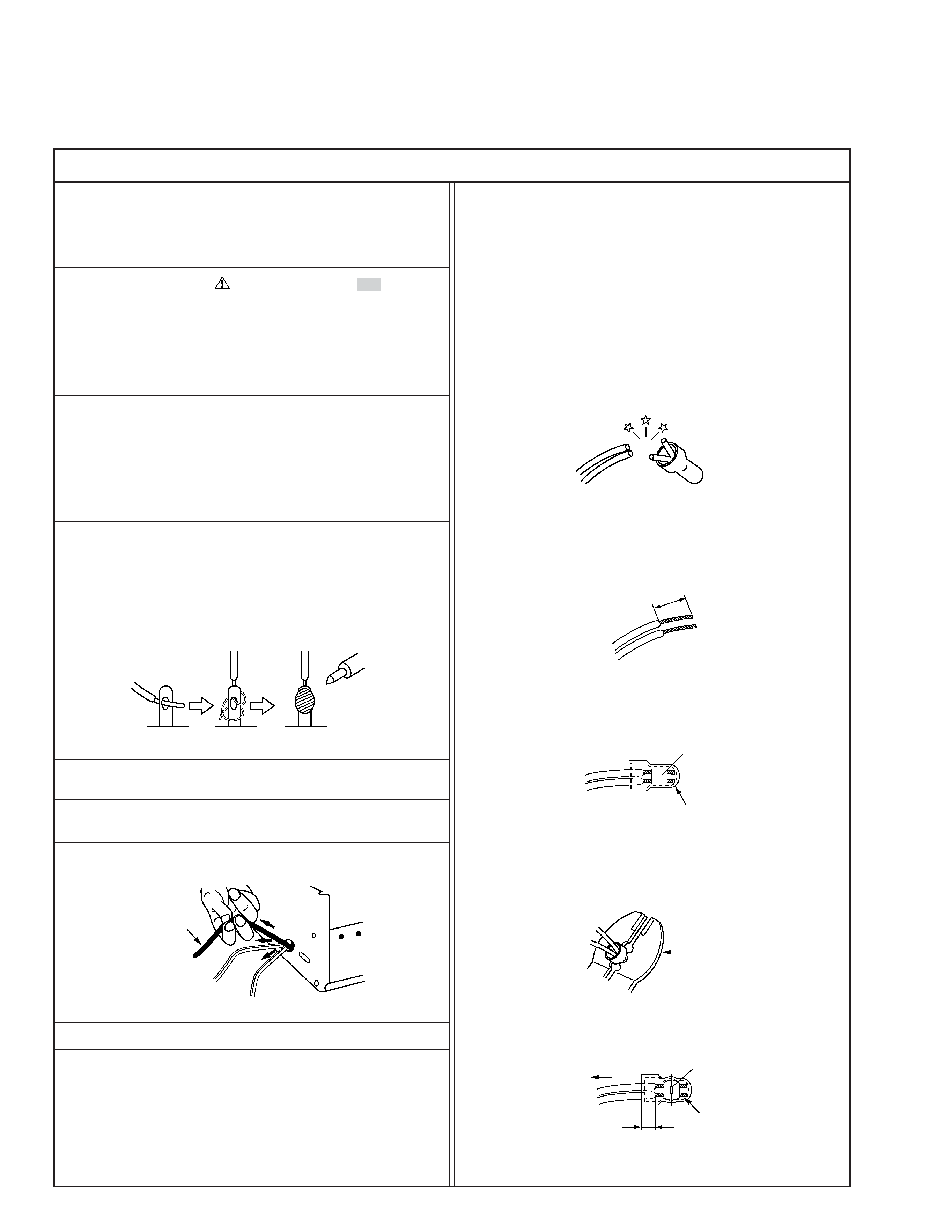
6. When replacing AC primary side components (transformers,
power cords, noise blocking capacitors, etc.) wrap ends of
wires securely about the terminals before soldering.
Power cord
Fig.2
10. Also check areas surrounding repaired locations.
11. Products using cathode ray tubes (CRTs)
In regard to such products, the cathode ray tubes themselves,
the high voltage circuits, and related circuits are specified for
compliance with recognized codes pertaining to X-ray emission.
Consequently, when servicing these products, replace the cath-
ode ray tubes and other parts with only the specified parts.
Under no circumstances attempt to modify these circuits.
Unauthorized modification can increase the high voltage value
and cause X-ray emission from the cathode ray tube.
12. Crimp type wire connector
In such cases as when replacing the power transformer in sets
where the connections between the power cord and power
transformer primary lead wires are performed using crimp type
connectors, if replacing the connectors is unavoidable, in or-
der to prevent safety hazards, perform carefully and precisely
according to the following steps.
1) Connector part number : E03830-001
2) Required tool : Connector crimping tool of the proper type
which will not damage insulated parts.
3) Replacement procedure
(1) Remove the old connector by cutting the wires at a point
close to the connector.
Important : Do not reuse a connector (discard it).
Fig.7
cut close to connector
Fig.3
(2) Strip about 15 mm of the insulation from the ends of
the wires. If the wires are stranded, twist the strands to
avoid frayed conductors.
15 mm
Fig.4
(3) Align the lengths of the wires to be connected. Insert
the wires fully into the connector.
Connector
Metal sleeve
Fig.5
(4) As shown in Fig.6, use the crimping tool to crimp the
metal sleeve at the center position. Be sure to crimp fully
to the complete closure of the tool.
1
Precautions during Servicing
7. Observe that wires do not contact heat producing parts
(heatsinks, oxide metal film resistors, fusible resistors, etc.)
8. Check that replaced wires do not contact sharp edged or
pointed parts.
9. When a power cord has been replaced, check that 10-15 kg of
force in any direction will not loosen it.
1.25
2.0
5.5
Crimping tool
Fig.6
(5) Check the four points noted in Fig.7.
Not easily pulled free
Crimped at approx. center
of metal sleeve
Conductors extended
Wire insulation recessed
more than 4 mm
S40888-01