Models 36SDX01SR/36SDX01S and 36SDX88B are in the same Solid State Color Television fam-
ily. The main difference between the 36SDX01SR/36SDX01S and 36SDX88B is the control panel
and the CRT.
Please refer to model 36SDX88B schematics, assembly, wiring, test and trou-
bleshooting information when servicing models 36SDX01SR/36SDX01S. Refer to Service Manual
PA No. 0110 issued in December 1998.
PA
36SDX01SR/MM1R
36SDX01S/MM1T
No. 0140
R/C: CLU-433FC
Please refer to Service Manual PA No. 0110 when adjusting 36SDX01SR/36SDX01S. The only difference is the Chopper Voltage as
stated below.
SPECIFICATIONS AND PARTS ARE SUBJECT TO CHANGE FOR IMPROVEMENT
SOLID STATE COLOR TELEVISION
MAY 2000
HHEA-MANUFACTURING DIVISION
NTSC
MM1R/MM1T
SERVICE MANUAL
ADJUSTMENT
#
CHOPPER VOLTAGE ADJUSTMENT
VGA MODE=112
±0.5V
VGA MODE=112
±0.5V
VGA MODE=105
±0.5V
(PA No. 0110 SECTION 2.3.1 PAGE 47)
DTV MODE=124
±0.5V
DTV MODE=124
±0.5V
DTV MODE=120
±0.5V
SVGA MODE=140
±0.5V SVGA MODE=140±0.5V SVGA MODE=135±0.5V
SYMBOL
NO.
DESCRIPTION
36SDX88B/MM1
36SDX01SR/MM1R
36SDX01S/MM1T
RT01
FOCUS ADJUSTMENT
SAME AS STATED
SAME AS STATED
SEE BELOW
(PA No. 0110 SECTION 3.3 PAGE 81)
IN PA No. 0110.
IN PA No. 0110.
5. Vertical Line Adjustment
Adjust Focus on Cross-Hatch Circle Pattern focusing
the point as shown in the right figure.
6. Adjust RT01 focusing only at vertical line so that it
becomes the most thick; the adjustment point which
can be seen the clearest without any saturation.
Concentration point:
Inner point of the circle as shown in the fight figure.
Note:
Adjust Horizontal Center Focus again after adjusting
Vertical Focus.
The end of
Cross-Hatch
The second vertical line from
the left end.
RT01
CPT PWB
REAR VIEW
36SDX01S/MM1T ONLY
2
This parts list only gives parts which are different from the service manual PA No. 0110. Components having special safety charac-
teristics are identified by a
on the parts list in this Service Data and its supplements and bulletins. Before servicing the chassis,
it is important that the service technician read and follow the ÒSafety PrecautionsÓ and ÒProduct Safety NoticesÓ in this Service Manual.
Do not degrade the safety of the receiver through improper servicing.
!
REPLACEMENT PARTS LIST
CG08
CAP 2125 CHIP 100000PF-K B 25V TA
0893027R
--
--
D611
ZENER DIODE
2339825M
2339825M
2339837M
DG09
ZENER HZS12 (C3) 0.005A
2339889M
--
--
DG12
DIODE 1SS254TZ/1SS270TA
2344041M
--
--
DG13
DIODE 1SS254TA/1SS270TA
2344041M
--
--
E801
CRT SOCKET
EY00411
EY00411
2698675
ESF
FOCUS SCREEN LEAD
EZ01001
EZ01001
EZ01003
EVV
CONNECTOR (VM)
2973695S
2973695S
2976645
EWK
3P CONNECTOR
2973715S
--
--
SYMBOL
NO.
DESCRIPTION
36SDX88B/MM1
36SDX01SR/MM1R
36SDX01S/MM1T
(5) Select MOVIE RATINGS MPAA (PG-13) and TV
RATINGS (TV-Y7/ALL BLOCK)
(6) Check that Picture & audio should be blocked as
follows
"RATING BLOCKED" is displayed when picture is
blocked.
(7) Same check as (1) to (6) should be applied for
PINP sub picture. Main picture should receive a
channel without V-chip signal. Sub picture should
receive a channel with V-chip signal.
NOTE: User setting rating & receive signal rating are
displayed on top area of the screen when
RECALL button is pressed.
1st line : User setting rating.
2nd line : Receive signal rating.
Receive Signal
TV-PG
MPAA PG
TV-Y7-FV
Picture/Audio
BLOCK
UNBLOCK
UNBLOCK
Condition
Receive Signal
TV-PG
MPAA PG
TV-Y7-FV
Picture/Audio
BLOCK
UNBLOCK
BLOCK
Condition
PARENTAL CONTROL (V-Chip) operation check
Preparation for Adjustment
(1) Receive a channel with V-Chip signal.
(2) Push MENU and select CUSTOM menu by using
or
button.
(3) Select PARENTAL CONTROL by using
or
button.
(4) Press
button to set PARENTAL CONTROL
mode.
(5) Enter "7777" for SECRET CODE.
(6) Select MOVIE RATINGS and TV RATING by
using
or
button.
(7) Press
button to set MOVIE RATINGS and TV
RATINGS.
Adjustment Procedure
(1) Select MOVIE RATINGS MPAA (PG) and TV
RATINGS (TV-14/ALL BLOCK)
(2) Check that Picture & audio should be blocked as
follows
"RATING BLOCKED" is displayed when picture is
blocked.
(3) Select MOVIE RATINGS MPAA (PG-13) and TV
RATINGS (TV-14/ALL BLOCK)
(4) Check that Picture & audio should be blocked as
follows
"RATING BLOCKED" is displayed when picture is
blocked.
Receive Signal
TV-PG
MPAA PG
TV-Y7-FV
Picture/Audio
UNBLOCK
BLOCK
UNBLOCK
Condition
36SDX01SR/MM1R AND 36SDX01S/MM1T ONLY
3
I001
MAIN MICRO-CONTROLLER
CP05361
CP05362
CP05362
JY91
3P(SW) PIN JACK WITH S
ES00022
--
--
JY91
JACK 03P HORIZONTAL
--
ES00261
ES00261
JY92
JACK S-TERMINAL
--
ES00271
ES00271
K400
JUMPER WIRE (0.5 L=52MM)
2974432M
--
--
K406
JUMPER WIRE (0.5 L=52MM)
2974432M
--
--
K411
JUMPER WIRE (0.5 L=52MM)
2974432M
--
--
K412
JUMPER WIRE (0.5 L=52MM)
2974432M
--
--
K421
JUMPER WIRE (0.5 L=52MM)
2974432M
--
--
K442
JUMPER WIRE (0.5 L=52MM)
2974432M
--
--
K481
JUMPER WIRE (0.5 L=52MM)
2974432M
--
--
K482
JUMPER WIRE (0.5 L=52MM)
2974432M
--
--
K8A1
JUMPER WIRE (0.5 L=52MM)
2974432M
--
--
K8A2
JUMPER WIRE (0.5 L=52MM)
2974432M
--
--
KT01
JUMPER WIRE (0.5 L=52MM)
--
--
2974432M
KT02
JUMPER WIRE (0.5 L=52MM)
--
--
2974432M
KT03
JUMPER WIRE (0.5 L=52MM)
--
--
2974432M
KT04
JUMPER WIRE (0.5 L=52MM)
--
--
2974432M
KT05
JUMPER WIRE (0.5 L=52MM)
--
--
2974432M
N201
INSTRUCTION BOOK
QR27362
QR45391
QR45391
N203
V-CHIP REFERENCE GUIDE
--
H462678
H462678
PVV
PLUG PIN SUB MINI
2902262
2902262
2902261
PWK
PLUG PIN SUB MINI 3P
2902262
--
--
R624
RESISTOR
0700056M
0700056M
0700062M
R625
RESISTOR
0700056M
0700056M
0700062M
R627
RESISTOR
0700054M
0700054M
0700058M
R627
RESISTOR
0700054M
0700054M
0700053M
RG18
1.2K OHM (1/16 W)
0195902R
0700042M
0700042M
RG30
RES.-CARBON FLM 1/16W 100-JB
0700027M
--
--
RG40
10K OHM (1/16 W)
0195925R
0700054M
0700054M
RKJ1
RES 2125 CHIP 1/16W 000 TAPE
0195250R
--
--
RKJ2
RES 2125 CHIP 1/16W 000 TAPE
0195250R
--
--
RKJ3
RES 3216 CHIP 1/8W 000 TAPE
0195248R
--
--
RKJ4
JUMPER
0195250R
2974432M
2974432M
RKJ5
JUMPER
0195250R
2974432M
2974432M
RT01
VARIABLE RESISTOR 20M
--
--
AW00241
SYMBOL
NO.
DESCRIPTION
36SDX88B/MM1
36SDX01SR/MM1R
36SDX01S/MM1T
This parts list only gives parts which are different from the service manual PA No. 0110. Components having special safety charac-
teristics are identified by a
on the parts list in this Service Data and its supplements and bulletins. Before servicing the chassis,
it is important that the service technician read and follow the ÒSafety PrecautionsÓ and ÒProduct Safety NoticesÓ in this Service Manual.
Do not degrade the safety of the receiver through improper servicing.
!
REPLACEMENT PARTS LIST
4
RL12
RESISTOR
0700033M
0700033M
0700029M
RL18
RESISTOR
0700036M
0700036M
0700032M
SG01
5 KEY PUSH SWITCH
2632851
2633322
2633322
SG02
PUSH SWITCH
2634621
FE10332R
FE10332R
SG03
PUSH SWITCH
2634621
FE10332R
FE10332R
TH01
FBT
BW00757
BW00757
BW02491
UG02
IC TPS831
CZ00781
--
--
V1
PICTURE TUBE
DE01351
DE01351
DE01921
(A90AGW14X04)
(A90AGW14X04)
(M90AHL50X33)
#030
FRONT FRAME
QD03492
QD09791
QD09791
#030
BACK COVER
Q001574
QD09621
QD09621
SYMBOL
NO.
DESCRIPTION
36SDX88B/MM1
36SDX01SR/MM1R
36SDX01S/MM1T
!
This parts list only gives parts which are different from the service manual PA No. 0110. Components having special safety charac-
teristics are identified by a
on the parts list in this Service Data and its supplements and bulletins. Before servicing the chassis,
it is important that the service technician read and follow the ÒSafety PrecautionsÓ and ÒProduct Safety NoticesÓ in this Service Manual.
Do not degrade the safety of the receiver through improper servicing.
!
REPLACEMENT PARTS LIST
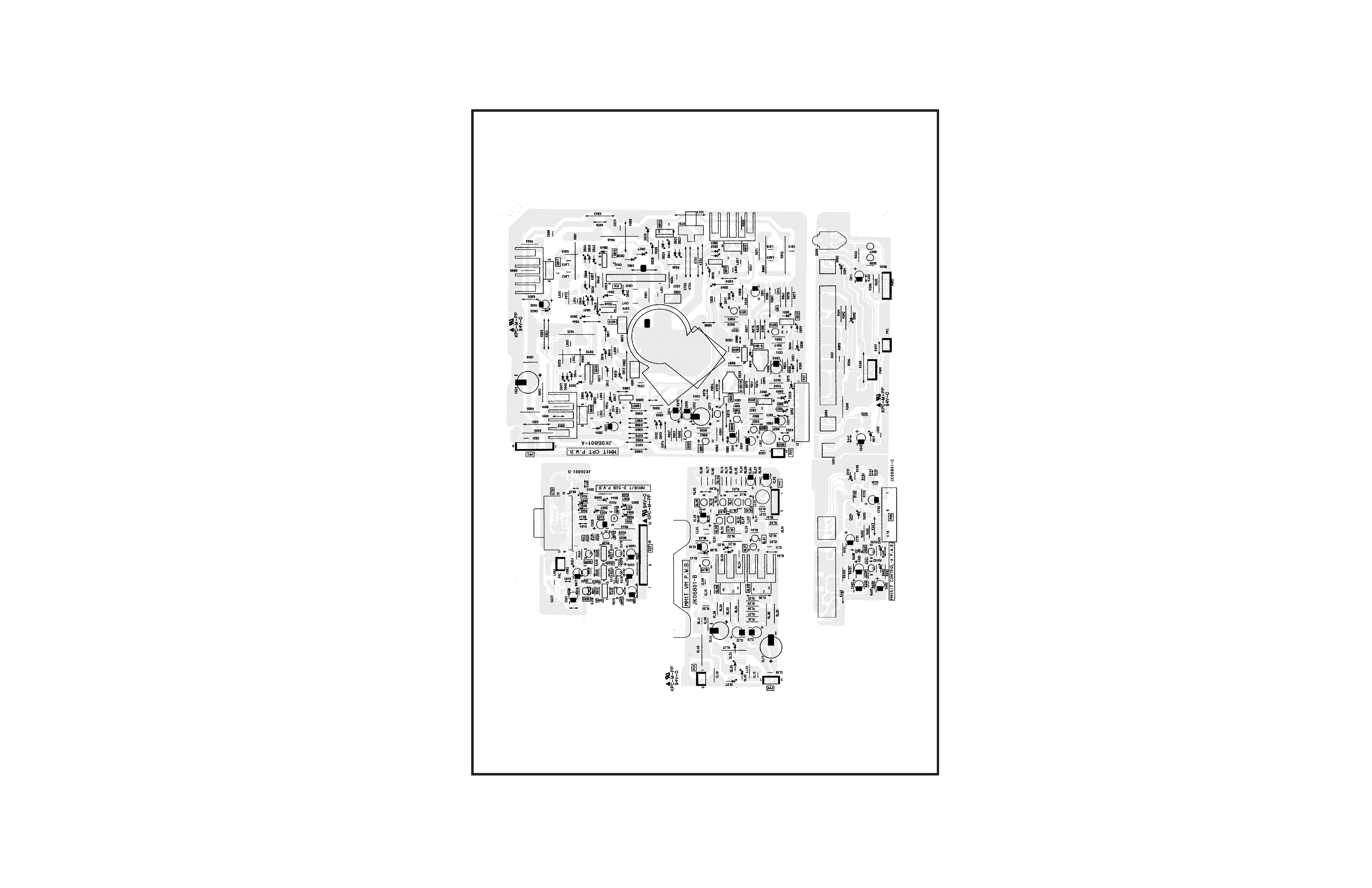
PRINTED CIRCUIT BOARD
CPT P.W.B.
5