+,7$&+,
SERVICE MANUAL
PA
No. 0139
R/C:
27UX01B-501
27UX01B-511
CLU-432UG
CAUTION:
Before servicing this chassis, it is important that the service technician read the "Safety
Precaution" and "Product Safety Notices" in this Service Manual.
CONTENTS
SOLID STATE COLOR TELEVISION
SPECIFICATIONS AND PARTS ARE SUBJECT TO CHANGE FOR IMPROVEMENT
JUNE 2000
HHEA-MANUFACTURING DIVISION
SAFETY PRECAUTIONS . . . . . . . . . . . . . . . . . . . . . . . . . . . . . . . . . . . . 2
PRODUCT SAFETY NOTICE . . . . . . . . . . . . . . . . . . . . . . . . . . . . . . . . . 4
POWER SOURCE . . . . . . . . . . . . . . . . . . . . . . . . . . . . . . . . . . . . . . . . . . 4
SERVICE NOTES . . . . . . . . . . . . . . . . . . . . . . . . . . . . . . . . . . . . . . . . . . 5
SPECIFICATIONS . . . . . . . . . . . . . . . . . . . . . . . . . . . . . . . . . . . . . . . . . . 6
OPERATION . . . . . . . . . . . . . . . . . . . . . . . . . . . . . . . . . . . . . . . . . . . . . . 7
SERVICE . . . . . . . . . . . . . . . . . . . . . . . . . . . . . . . . . . . . . . . . . . . . . . . . 15
CIRCUITS AND BLOCK DIAGRAMS . . . . . . . . . . . . . . . . . . . . . . . . . . 34
PARTS IDENTIFICATION . . . . . . . . . . . . . . . . . . . . . . . . . . . . . . . . . . . 38
PARTS LIST . . . . . . . . . . . . . . . . . . . . . . . . . . . . . . . . . . . . . . . . . . . . . . 41
This television will display television Closed
Captioning (
or
) in accordance
with paragraph 15.119 of the FCC rules.
CC
NA8 CHASSIS
NTSC
- 2 -
SAFETY PRECAUTIONS
NOTICE:
Comply with all cautions and safety-related
notes located on or inside the cabinet and on the chasis or
picture tube.
WARNING: Since the chasis of this receiver is connected
to one side of the AC power supply during operation,
whenever the receiver is plugged in, service should not be
attempted by anyone unfamiliar with the precautions
necessary when working on this type of receiver.
The following precautions should be observed:
1. Do not install, remove, or handle the picture tube in any
manner unless shatterproof goggles are worn. People
not so equipped should be kept away from the picture
tube while handling.
2. When service is required, an isolation transformer
should be inserted between power line and the receiver
before any service is performed on a "HOT" chassis
receiver.
3. When replacing a chassis in the receiver, all protective
devices must be put back in place, such as barriers,
nonmetallic
knobs,
adjustment
and
compartment
covershields, isolation resistors, capacitors, etc.
4. When service is required, observe the original lead
dress in the high voltage circuitry area.
5. Always
use
the
manufacturer's
replacement
components. Critical components as indicated on the
circuit diagram should not be replaced by another
manufacturer's. Furthermore, where a short circuit has
occurred, replace those components that indicate
evidence of overheating.
6. Before returning a serviced receiver to the customer, the
service technician must thoroughly test the unit to be
certain that it is completely safe to operate without
danger of electrical shock, and be sure that no
protective device built into the receiver has become
defective, or inadvertently defeated during servicing.
Therefore, the following checks should be performed for
the continued
protection of the customer and service
technician.
Leakage Current Cold Check
With the AC plug removed from the 120V AC 60Hz source,
place a jumper across the two plug prongs. Turn the AC
power switch ON. Using an insulation tester (DC500V),
connect one lead to the jumpered AC plug and touch the
other lead to each exposed metal part (antennas,
screwheads,
metal
overlays,
control
shafts,
etc.),
particularly any exposed metal part having a return path to
the chassis should have a minimum resistor reading of
0.24M
and a maximum resistor reading of 12M. Any
resistance value below or above this range indicates an
abnormality which requires corrective action. An exposed
metal part not having a return path to the chassis will
indicate an open circuit.
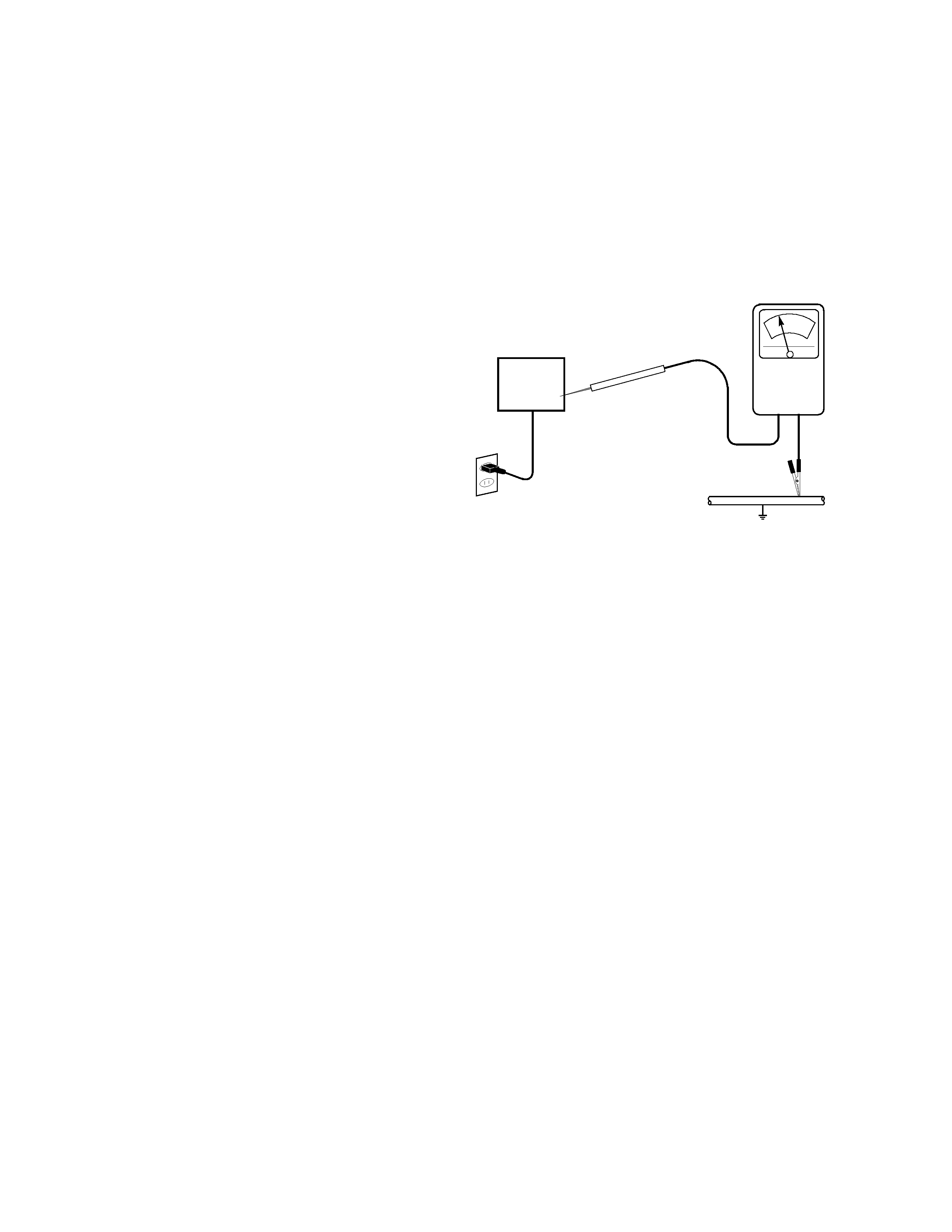
Leakage Current Hot Check
Plug the AC cord directly into a 120V AC 60Hz outlet (do
not use an isolated transformer for this check). Turn the
AC power ON.
Using a Leakage Current Tester
(Simpson's Model 229 or equivalent), measure for current
from all exposed metal parts of the cabinet (antennas,
screwheads, overlays, control shafts, etc.). Any current
measured must not exceed 0.5 milliamps.
AC LEAKAGE TEST
ANY MEASUREMENTS NOT WITHIN THE LIMITS
OUTLINED
ABOVE
ARE
INDICATIVE
OF
A
POTENTIAL SHOCK HAZARD AND MUST BE
CORRECTED
BEFORE
RETURNING
THE
RECEIVER TO THE CUSTOMER.
High voltage
This receiver is provided with a hold down circuit for clearly
indicating that voltage has increased in excess of a
predetermined value. Comply with all notes described in
this service manual regarding this hold down circuit when
servicing, so that this hold down circuit is operated
correctly.
Serviceman Warning
With
minimum
BRIGHTNESS,
CONTRAST,
SHARPNESS, and COLOR, the operating high voltage in
this receiver is lower than 28.30kV ±1.25kV. In case any
component having influence on the high voltage is
replaced,
confirm
that
high
voltage
with
minimum
BRIGHTNESS, CONTRAST, SHARPNESS, and COLOR
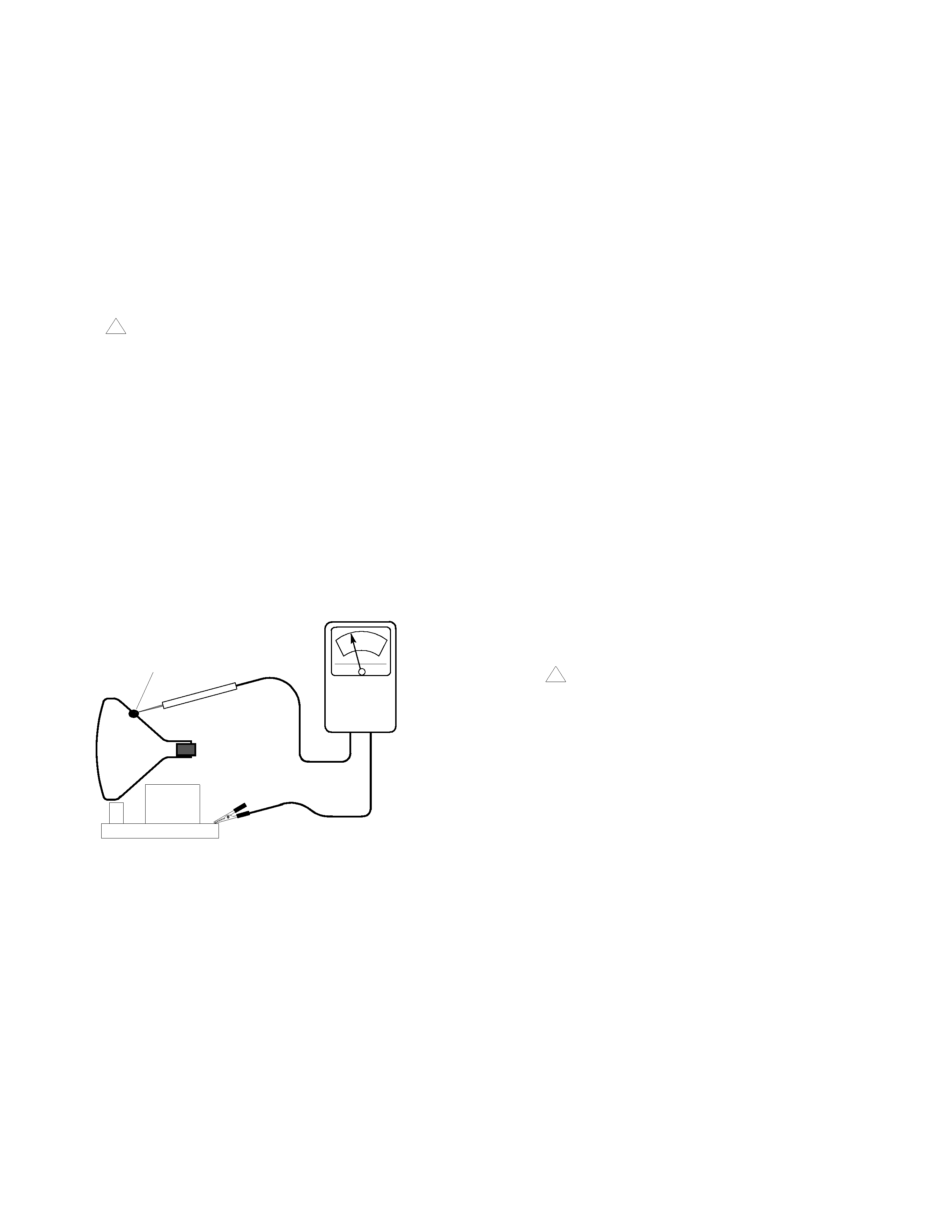
is lower than 28.30kV ±1.25kV. To measure high voltage
use a High Impedance High Voltage meter. Connect (-) to
chassis earth and (+) to the CRT ANODE button. (See the
connection diagram on page 4.)
Note:
Turn power switch OFF without fail before the
connection to the Anode Button
LEAKAGE
CURRENT
TESTER
ALSO TEST WITH
PLUG REVERSED
(USING AC ADAPTER
PLUG AS REQUIRED)
DEVICE
UNDER
TEST
(READING
SHOULD NOT BE
ABOVE 0.5mA)
2-WIRE CORD
TEST ALL
EXPOSED METAL
SURFACES
+-
EARTH
GROUND
- 3 -
Important Safety Notice . . . . . . . . . . . . . . . . . . 2
Safety Precautions . . . . . . . . . . . . . . . . . 2
Product Safety Notice . . . . . . . . . . . . . . . . . . . . 4
Horizontal Oscillator Disable Circuit . . . . 5
Receiver Feature Table . . . . . . . . . . . . . . . . . . . 6
Location of Controls (Receiver)
Receiver Front Control Panel . . . . . . . . . 7
Location of Controls (Remote). . . . . . . . . . . . . 8
Disassembly for Service . . . . . . . . . . . . . . . . . 15
Disassembly for CRT Replacement . . . . . . . . 15
Chassis Service Adjustment Procedures . . . 16
131.0V B+ Voltage Confirmation . . . . . 16
Source Voltage Chart . . . . . . . . . . . . . . 16
B+ 5V Source Voltages. . . . . . . . . . . . . 16
MPU 5V . . . . . . . . . . . . . . . . . . . . . . . . 16
Stand-by 5V . . . . . . . . . . . . . . . . . . . . . 16
B+ 9V Source Voltage . . . . . . . . . . . . . 16
B+ 12V (Stand-by) . . . . . . . . . . . . . . . . 16
High Voltage Check . . . . . . . . . . . . . . . 16
Purity and Convergence Procedures . . . . . . 17
Serviceman Mode (Electronic Controls) . . . . 20
Entering Serviceman Mode . . . . . . . . . 20
Toggle between Modes. . . . . . . . . . . . . 20
Exiting the Serviceman Mode . . . . . . . . 20
Sub-Data Adjustment . . . . . . . . . . . . . . 21
Cut-Off Adjustment . . . . . . . . . . . . . . . . 21
Pin Cushion Adjustment . . . . . . . . . . . . 22
MTS Adjustment . . . . . . . . . . . . . . . . . . 22
PIP Adjustment . . . . . . . . . . . . . . . . . . . 23
Options Adjustment . . . . . . . . . . . . . . . 24
Comb Filter Adustment . . . . . . . . . . . . . 25
To Check Purity . . . . . . . . . . . . . . . . . . 26
Helpful Hints . . . . . . . . . . . . . . . . . . . . . 26
Instructional Flow Chart
for Serviceman Mode . . . . . . . . . . . . . . . . 27
Service Adjustments
(Electronic Control). . . . . . . . . . . . . . . . . . 30
Sub-Brightness . . . . . . . . . . . . . . . . . . . 30
Sub-Contrast. . . . . . . . . . . . . . . . . . . . . 30
Tint/Color Adjustment . . . . . . . . . . . . . . 30
Color Temperature Adjustment . . . . . . . 31
Horizontal Centering . . . . . . . . . . . . . . . 32
MTS Circuit Adjustment . . . . . . . . . . . . 32
Clock Adjustment (S7) . . . . . . . . . . . . . 33
Vertical Size . . . . . . . . . . . . . . . . . . . . . 33
Service Adjustments
(Mechanical Controls). . . . . . . . . . . . . . . . 33
Focus (Part of T551). . . . . . . . . . . . . . . 33
Audio Signal Path Block Diagram . . . . . . . . . 34
Video-Chroma Signal Path
Block Diagrams . . . . . . . . . . . . . . . . . . . . . 35
IC101 VCJ IN/OUT Pins and Functions . . . . . 36
IC001 MPU IN/OUT Pins and Functions. . . . . 37
Component Identification . . . . . . . . . . . . . . . . 38
Parts List . . . . . . . . . . . . . . . . . . . . . . . . . . . . . 41
- 4 -
PRODUCT SAFETY NOTICE
Many electrical and mechanical parts in HITACHI
television
receivers
have
special
safety-related
characteristics. These are often not evident from visual
inspection nor can the protection afforded by them
necessarily be obtained by using replacement components
rated for higher voltage, wattage, etc. Replacement parts
which have these special safety characteristics are
identified in this Service manual.
Electrical components having such features are identified
with a
mark in the schematics and parts list in this
Service Manual.
The use of a substitute replacement component which
does not have the same safety characteristics as the
HITACHI recommended replacement component, shown
in the parts list in this Service Manual, may create shock,
fire, X-radiation, or other hazards.
Production safety is continuously under review and new
instructions are issued from time to time. For the latest
information, always consult the current HITACHI Service
Manual.
[A subscription to, or additional copies of
HITACHI Service Manuals may be obtained at a nominal
charge from HITACHI Sales Corporation.]
X-Radiation
TUBE: The primary source of X-Radiation in this receiver
is the picture tube.
The tube utilized in this chassis is
specially constructed to limit X-Radiation emissions. For
continued X-Radiation protection, the replacement tube
must be the same type as the original HITACHI-approved
type.
When troubleshooting and making test measurements in a
receiver with excessive high voltage problem, avoid being
unnecessarily close to the picture tube and high voltage
components.
Do not operate the chassis longer than is necessary to
locate the cause of excessive voltage.
This Service Manual is intended for qualified service
technicians; it is not meant for the casual do-it-yourselfer.
Qualified technicians have the necessary test equipment
and tools, and have been trained to properly and safely
repair complex products such as those covered by this
manual.
Improperly performed repairs can adversely
affect the safety and reliability of the product and may void
warranty.
Consumers should not risk trying to do the
necessary repairs and should refer to a qualified service
technician.
WARNING
Lead in solder used in this product is listed by the California
Health and Welfare agency as a known reproductive
toxicant
which
may
cause
birth
defects
or
other
reproductive harm (California Health and Safety Code,
Section 25249.5).
When servicing or handling circuit boards and other
components
which
contain
lead
in
solder,
avoid
unprotected skin contact with solder. Also, when soldering
do not inhale any smoke or fumes produced.
SAFETY NOTICE
USE ISOLATION TRANSFORMER
WHEN SERVICING
Components
having
special
safety
characteristics
identified by
on the parts list in this service manual and
its supplements and bulletins.
Before servicing this
product, it is important that the service technician read and
follow the "Safety Precautions" and the "Product Safety
Notices" in this Service Manual.
For continued X-Radiation protection, replace picture tube
with original type or HITACHI equivalent type.
POWER SOURCE
This television receiver is designed to operate on 120Volt/
60Hz, AC house current.
Insert the power cord into a
120Volts/60Hz outlet.
NEVER CONNECT THE TV TO OTHER THAN THE
SPECIFIED VOLTAGE OR TO DIRECT CURRENT.
!
HIGH
IMPEDANCE
H.V. METER
CRT ANODE
+-
CHASSIS
GROUND
CRT
!

- 5 -
Service Notes
IMPORTANT: To protect against possible damage to
the solid state devices due to arcing or static
discharge, make certain that all ground wires and CRT
DAG wire are securely connected.
CAUTION: The power supply circuit is above earth
ground and the chassis cannot be polarized. Use an
isolation transformer when servicing the Receiver to
avoid damage to the test equipment or to the chassis.
Connect the test equipment to the proper ground ( ) or
(
) when servicing, or incorrect voltages will be
measured.
WARNING: This Receiver has been designed to meet
or exceed applicable safety and X-ray radiation
protection as specified by government agencies and
independent testing laboratories.
To maintain original product safety design standards
relative to X-ray radiation and shock and fire hazard,
parts indicated with the symbol
on the schematic
must be replaced with identical parts. Order parts from
the manufacturer's parts center using the parts
numbers shown in this service manual, or provide the
chassis number and the part reference number.
For optimum performance and reliability, all other parts
should
be
replaced
with
components
of
identical specification.
Horizontal Oscillator Disable Circuit
This chassis employs a special circuit to protect
against excessive high voltage and beam current. If, for
any reason, the high voltage and beam current exceed
a predetermined level this protective circuit activates
and detunes the horizontal oscillator that limits the high
voltage. The over-voltage protection circuit is not
adjustable. However, if components indicated by the
symbol
on the schematic in either the horizontal
sweep system or the over-voltage protection circuit
itself are changed, the operation of the circuit should
be checked using the following procedure:
Equipment needed to check the disabled circuit:
1. Voltmeter (0 - 200V scale)
2. High Voltage Meter (0- 50kV)
3. Variac or Isolation Transformer
Procedure:
1.
Tune in a station to verify that the horizontal is
in sync.
2.
Obtain a Monoscope pattern or a signal generator
crosshatch pattern
3.
Turn the Receiver OFF. Connect a jumper across
IC803 pin 3 and pin 4. Apply +9V DC to cathode of
D001.
4.
Reduce the AC supply voltage to approximately
45V. Connect the high voltage meter to the CRT
anode. (H.V. button).
Note:
Use the Dag Ground (C10 on the CRT Board)
to connect the (-) lead of the meter.
5.
Turn the Receiver ON. Slowly increase the AC
supply voltage and verify that the high voltages
does not exceed 37.1kV, when horizontal just
begins to pull out of sync. If the high voltage is not
within the specified limit, the cause must be
determined and corrected before the Receiver is
returned to the customer.
!
!