- 1 -
EN-1204D
Published by Service Dept.
Printed in Japan
Clarion Co., Ltd.
50 Kamitoda, Toda-shi, Saitama 335-8511 Japan
Service Dept.: 5-66 Azuma , Kitamoto-shi, Saitama 364-0007 Japan
Tel: +81-48-541-2335 / 2432 FAX: +81-48-541-2703
298-6078-00 Jun.2003
Service Manual
Model
NISSAN Automobile Genuine
Woofer Amplifier
EN-1204D
(Genuine No.28060 7Y000)
SPECIFICATIONS
Gain:
10+3dB/-3dB(280mV,60Hz)
S/N ratio:
More than 74dB(60Hz)
Distortion:
Less than 0.2%(60Hz)
Maximum power output:
40W x2
Speaker impedance:
2 ohm
Power supply voltage: DC13.2V
negative ground
Dimensions(mm):
107(W) x36(H) x110(D)
Weight:
800g
CAUTION
*
We cannot supply PWB with component parts in prin-
ciple. When a circuit on PWB has failure , please repair
it by component parts base. Parts which are not men-
tioned in service manual are not supplied.
*
Specification and design are subject to change without
notice for further improvement.
COMPONENTS
EN-1204D-A
Main unit
---------
1
product liability (PL) shall not be our responsibility in
cases where an accident or failure is as a result of un-
specified parts being used.
2. Place the parts and wiring back in their original positions
after replacement or re-wiring.
For proper circuit construction, use of insulation tubes,
bonding,gaps to PWB, etc, is involved. The wiring con-
nection and routing to the PWB are specially planned
using clamps to keep away from heated and high voltage
parts. Ensure that they are placed back in their original
positions after repair or inspection.
If extended damage is caused due to negligence during
repair, the legal responsibility shall be with the repairing
company.
3. Check for safety after repair.
Check that the screws, parts and wires are put back se-
curely in their original position after repair. Ensure for
safety reasons there is no possibility of secondary
ploblems around the repaired spots.
If extended damage is caused due to negligence of re-
pair, the legal responsibility shall be with the repairing
company.
4. Caution in removal and making wiring connection to the
parts for the automobile.
Disconnect the battery terminal after turning the ignition
key off. If wrong wiring connections are made with the
battery connected, a short circuit and/or fire may occur.
If extensive damage is caused due to negligence of re-
pair, the legal responsibility shall be with the repairing
company.
5. Cautions regarding chips.
Do not reuse removed chips even when no abnormality
is observed in their appearance. Always replace them
with new ones. (The chip parts include resistors, capaci-
tors, diodes, transistors, etc). The negative pole of tanta-
lum capacitors is highly susceptible to heat, so use spe-
cial care when replacing them and check the operation
afterwards.
To engineers in charge of repair or
inspection of our products.
Before repair or inspection, make sure to follow
the instructions so that customers and Engineers
in charge of repair or inspection can avoid suf-
fering any risk or injury.
1. Use specified parts.
The system uses parts with special safety features against
fire and voltage. Use only parts with equivalent charac-
teristics when replacing them.
The use of unspecified parts shall be regarded as re-
modeling for which we shall not be liable. The onus of
- 2 -
EN-1204D
6. Cautions in handling flexible PWB
Before working with a soldering iron, make sure that the
iron tip temperature is around 270
. Take care not to
apply the iron tip repeatedly(more than three times)to the
same patterns. Also take care not to apply the tip with
force.
7. Turn the unit OFF during disassembly and parts replace-
ment. Recheck all work before you apply power to the
unit.
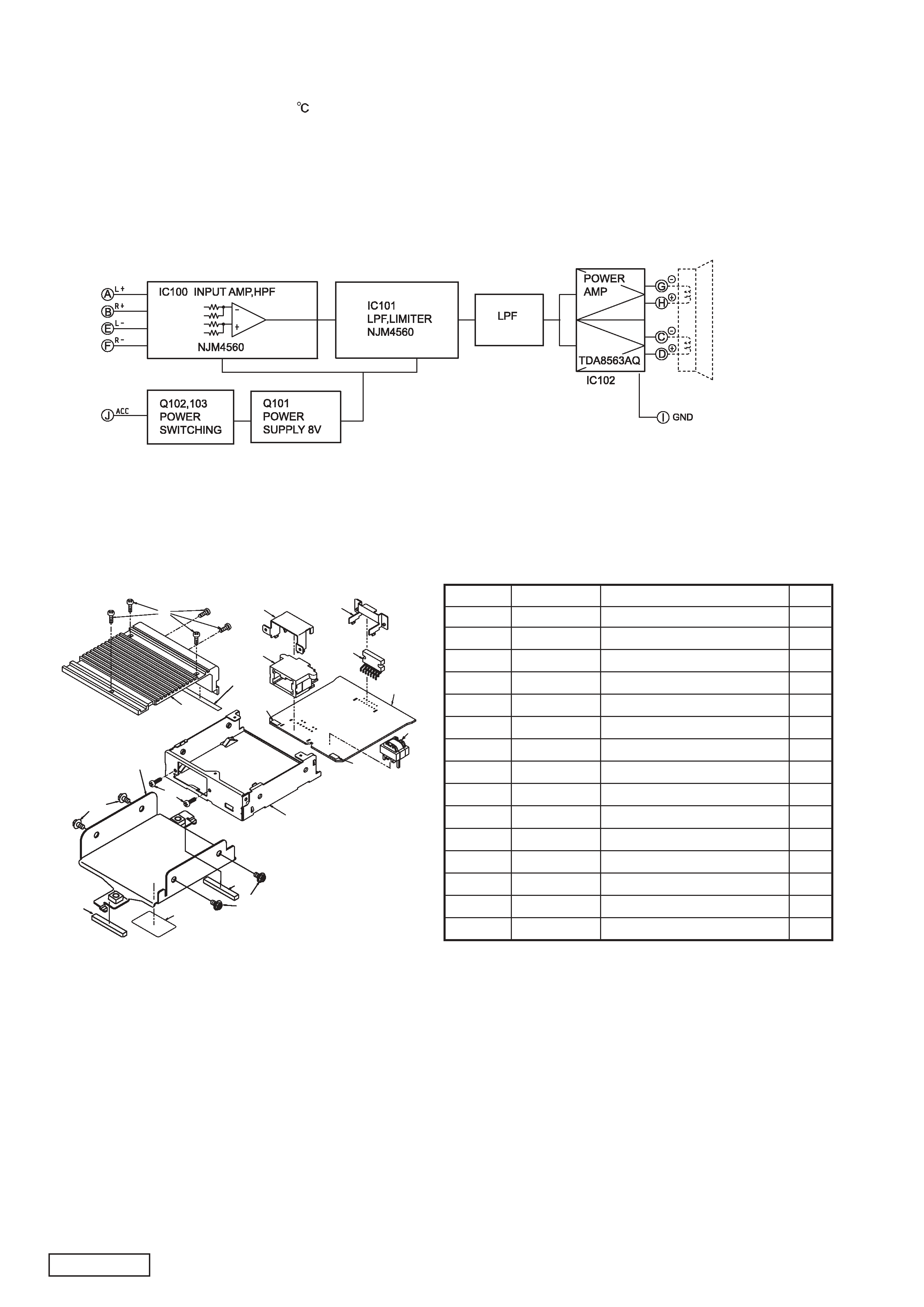
BLOCK DIAGRAM
9
5
4
13
15
11
13
12
10
11
1
9
15
14
3
8
7
6
2
EXPLODED VIEW/PARTS LIST
NO.
PART NO.
DESCRIPTION
Q'TY
1
311-1745-00
LOWER CASE
1
2
313-1732-00
HEAT SINK
1
3
039-1247-00
MAIN PWB(WITH COMPONENT) 1
4
074-1156-00
OUTLET SOCKET
1
5
331-2363-00
HOLDER
1
6
051-2048-00
IC (TDA8563AQ)
1
7
331-2404-00
IC HOLDER
1
8
009-0658-02
CHOKE
1
9
714-2610-81
MACHINE SCREW
7
10
300-7826-01
MTG-BRKT
1
11
716-3491-00
IT SCREW
4
12
286-8460-14
SETPLATE
1
13
345-8583-00
CUSHION RUBBER
2
14
345-8620-00
RUBBER PART
1
15
345-8621-00
RUBBER PART
2
- 3 -
EN-1204D
ELECTRICAL PARTS LIST
MAIN PWB(B1)
R111
032-0131-65 1/8W 100k ohm 0.F
R123
117-5621-15 1/8W 5.6k ohm
R124
117-4721-15 1/8W 4.7k ohm
R127
117-4721-15 1/8W 4.7k ohm
R128
111-1021-98 1/4W 1k ohm
R140
111-2231-98 1/4W 22k ohm
R141
111-1821-98 1/4W 1.8k ohm
R142
111-1041-98 1/4W 100k ohm
R143
111-2221-98 1/4W 2.2k ohm
R144
111-2231-98 1/4W 22k ohm
R200
117-5621-15 1/8W 5.6k ohm
R201
117-5631-15 1/8W 56k ohm
R204
111-3631-98 1/4W 36k ohm
R205
117-4331-15 1/8W 43k ohm
R206
117-1831-15 1/8W 18k ohm
R207
117-1831-15 1/8W 18k ohm
R208
117-3921-15 1/8W 3.9k ohm
R209
117-1021-15 1/8W 1k ohm
R210
117-2731-15 1/8W 27k ohm
R211
117-2221-15 1/8W 2.2k ohm
R212
111-2231-98 1/4W 22k ohm
R221
111-2221-98 1/4W 2.2k ohm
R300
111-6211-98 1/4W 620 ohm
R301
111-6211-98 1/4W 620 ohm
R302
117-1541-15 1/8W 150k ohm
R303
111-1051-98 1/4W 1M ohm
R304
117-1031-15 1/8W 10k ohm
R305
111-2221-98 1/4W 2.2k ohm
T100
009-0658-02 0.7mH
C312
176-2201-50 22pF CH
C401
172-1041-15 0.1uF
C402
172-5641-15 0.56uF
D100
001-0347-52 MA4110L
D102
001-0330-90 1SS119
D103
001-2015-00 RL253
D110
001-0429-00 S3V20
D301
001-0347-10 MA4030L
D302
001-0330-90 1SS119
D307
001-0466-90 S5688B
IC100
051-1080-91 NJM4560M
IC101
051-1080-91 NJM4560M
IC102
051-2048-00 TDA8563AQ
J100
074-1156-00 NS10-MW 10P
JW9001 117-0000-05 1/8W 0 ohm JW
JW9002 117-0000-05 1/8W 0 ohm JW
Q1
108-0030-35 2SK30
Q101
193-1858-00 2SD1858
Q102
192-2458-00 2SC2458
Q103
190-1048-00 2SA1048
R100
111-5611-98 1/4W 560 ohm
R101
111-5611-98 1/4W 560 ohm
R102
032-0131-60 1/8W 10k ohm 0.F
R103
032-0131-60 1/8W 10k ohm 0.F
R104
032-0131-60 1/8W 10k ohm 0.F
R105
032-0131-60 1/8W 10k ohm 0.F
R106
032-0131-66 1/8W 100 ohm 0.F
R107
032-0131-66 1/8W 100 ohm 0.F
R108
032-0131-60 1/8W 10k ohm 0.F
R109
032-0131-60 1/8W 10k ohm 0.F
R110
032-0131-65 1/8W 100k ohm 0.F
C100
042-0562-68 16V220uF
C101
042-0562-68 16V220uF
C102
042-0562-68 16V220uF
C103
042-0562-68 16V220uF
C104
042-0562-68 16V220uF
C105
042-0562-68 16V220uF
C106
176-1011-50 100pF CH
C108
176-1011-50 100pF CH
C112
042-0562-67 16V10uF
C113
172-8241-15 0.82uF
C114
172-1041-15 0.1uF
C115
042-0548-53 16V100uF
C117
042-0562-70 16V47uF
C118
172-5641-15 0.56uF
C128
172-1041-15 0.1uF
C129
042-0582-00 16V4700uF
C103
184-1083-32 16V1000uF
C132
176-1011-50 100pF CH
C133
176-1011-50 100pF CH
C134
183-4763-39 16V47uF
C200
172-4741-15 0.47uF
C201
172-4741-15 0.47uF
C203
172-3331-15 0.033uF
C204
182-4746-69 50V0.47uF NP
C205
172-3341-15 0.33uF
C207
172-1041-15 0.1uF
C225
176-1011-50 100pF CH
C226
176-1011-50 100pF CH
C300
178-1042-78 0.1uF
C310
176-2211-50 220pF CH
C311
176-1007-50 10pF CH
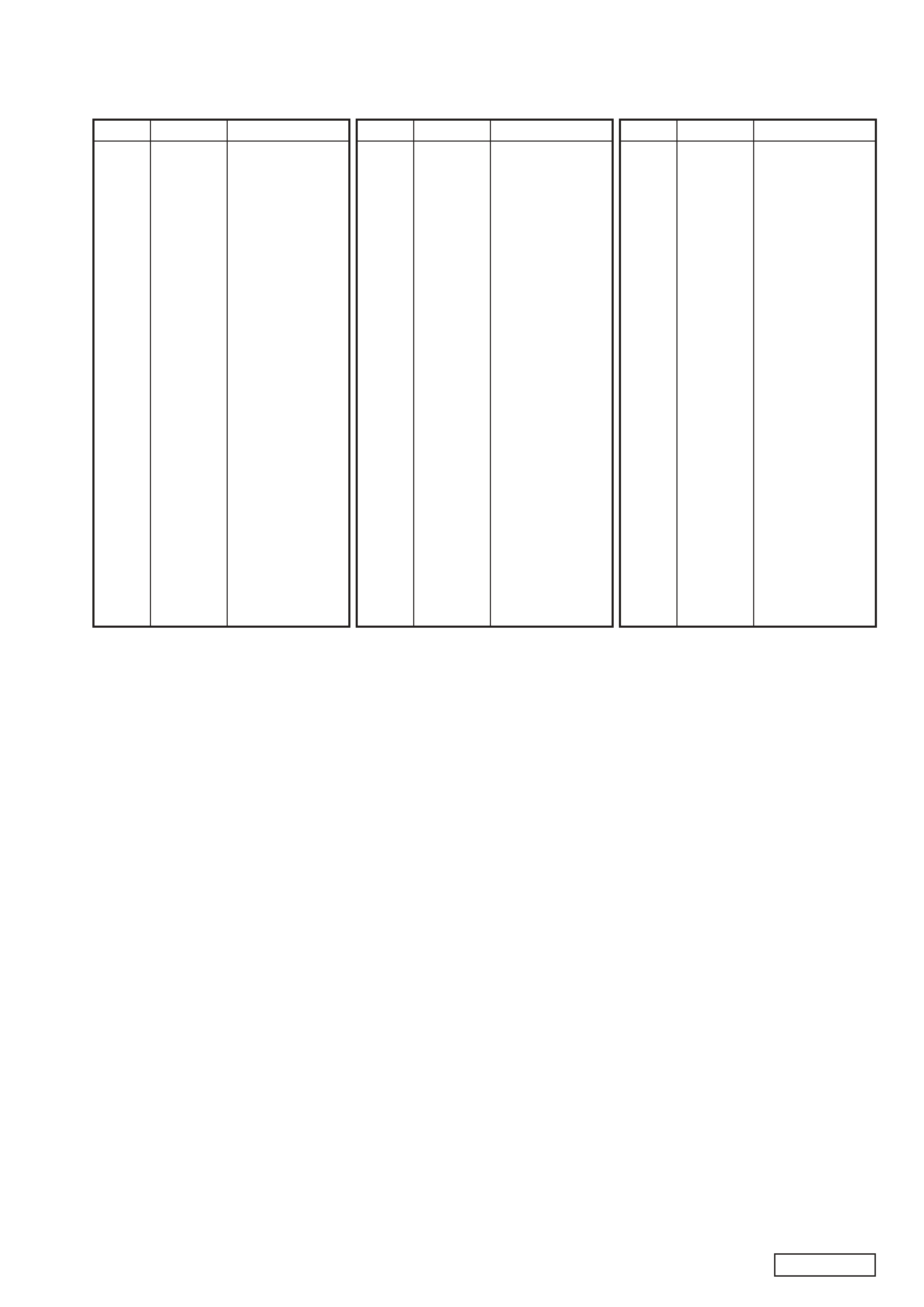
REF No. PART No.
DESCRIPTION
REF No. PART No.
DESCRIPTION
REF No. PART No.
DESCRIPTION
Ma in P W B S ection (B 1)
- 4 -
E N -1204D
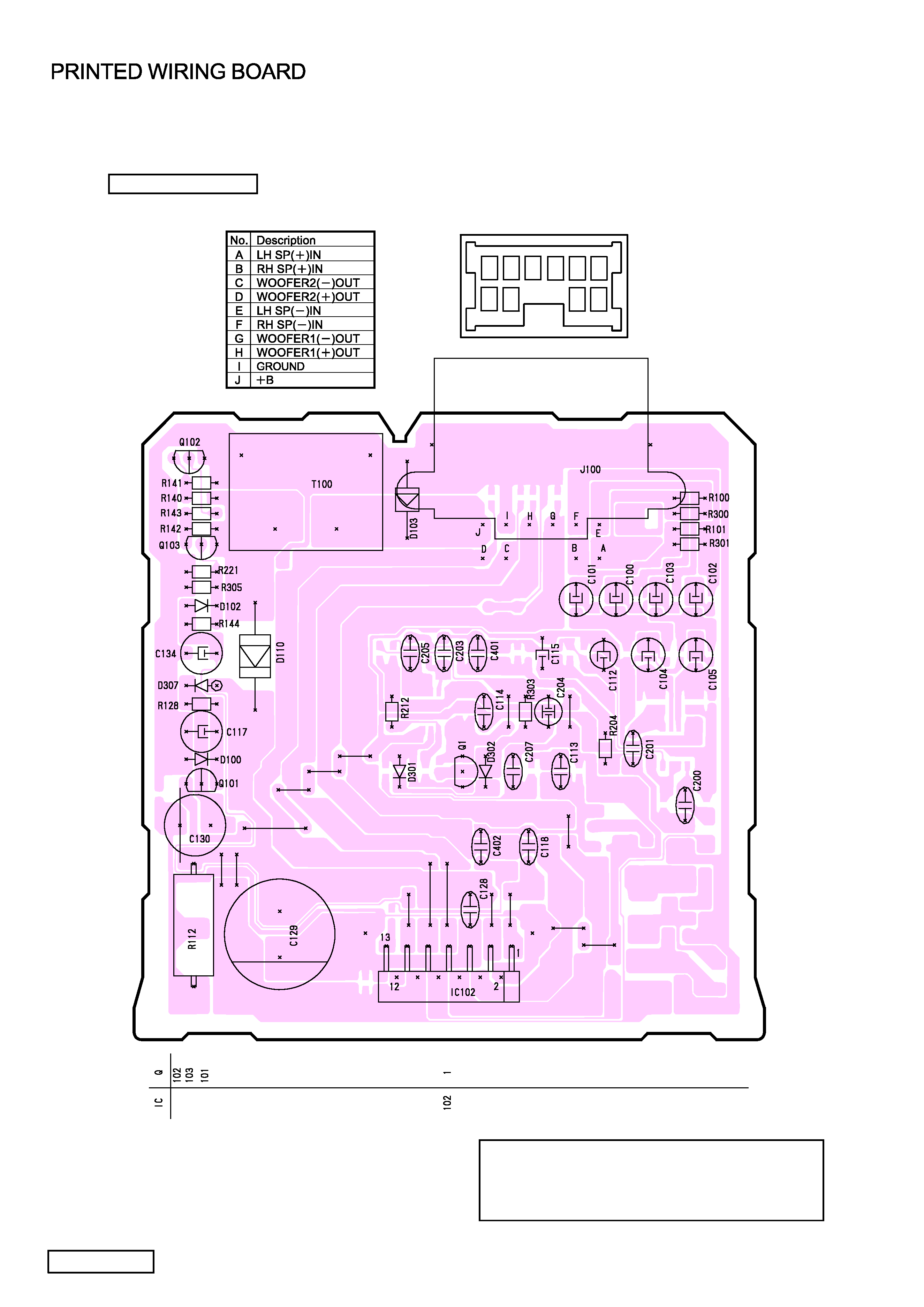
A
B
C D
E
F
G
H
I
J
COMPONENT SIDE
Caution:
COMPONENT SIDE: Parts on the component side seen
from the component side are indicated.
SOLDER SIDE: Parts on the solder side seen
from the solder side are indicated.
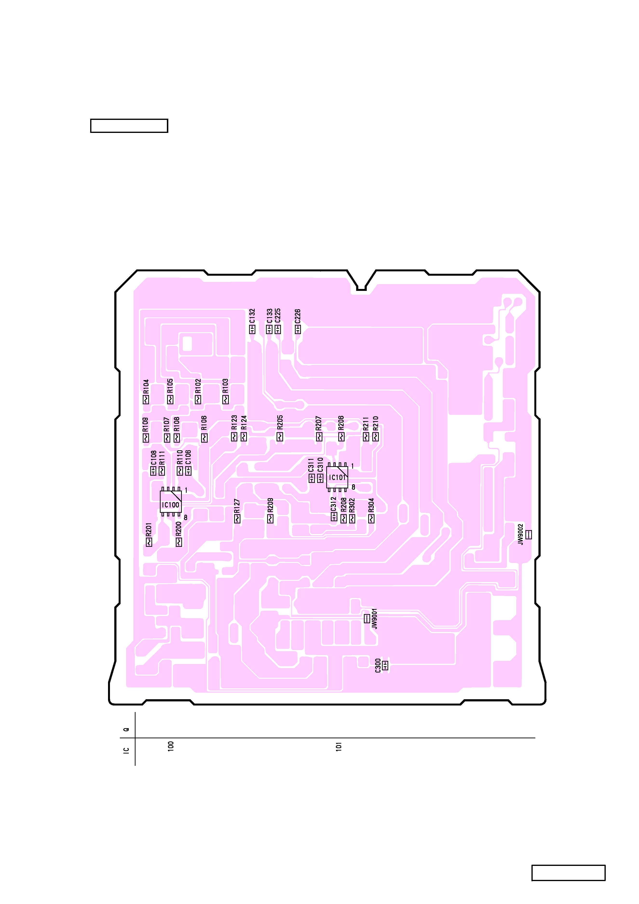
- 5 -
E N 1204D
Ma in P W B S ection (B 1)
SOLDER S IDE