- 1 -
PN-2301M/U
Published by Service Dept.
Printed in Japan
Clarion Co., Ltd.
Export Division - 22-3, Shibuya 2-chome, Shibuyaku, Tokyo, 150-8335 Japan
Tel: 03-3400-1121
Service Dept.- 50 kamitoda,Toda-shi,Saitama,335-8511 Japan Tel: 048-443-1111
FAX:048-433-6996
298-5825-00 Feb.2000 P
Service Manual
Model
NISSAN Automobile Genuine
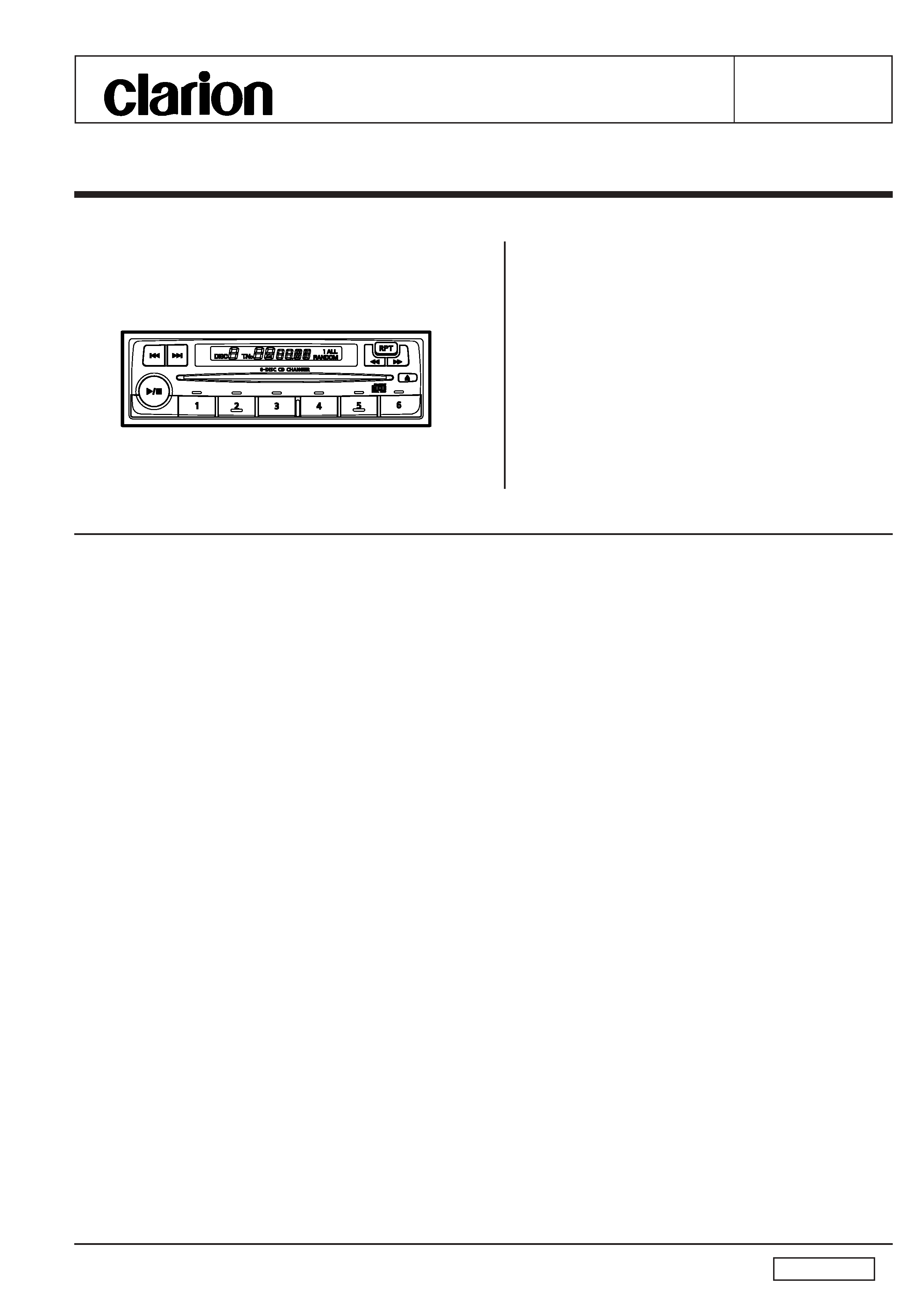
6-Disc CD Changer Deck
PN-2301M-A
(Genuine No. 28184 5M100
ID No.CE038)
PN-2301U-B
(Genuine No. B8182-C9964
ID No.CV919)
SPECIFICATIONS
Wow and flutter:
Less than 0.2%(W.R.M.S)
Frequency characteristics:
17 Hz to 20kHz (
2dB)
High frequency distortion:
0.02% (1 kHz)
S/N ratio:
80dB (1 kHz) IHF-A
Channel separation:
70 dB (1 kHz)
Power supply voltage: DC14.4V(10.8 to 15.6V)
Negative ground
Current consumption:
1A or Less
Dimensions(mm):
180(W)
54(H)
176(D)
Weight:
approx. 1.6kg
Specification and design are subject to change without
notice for further improvement.
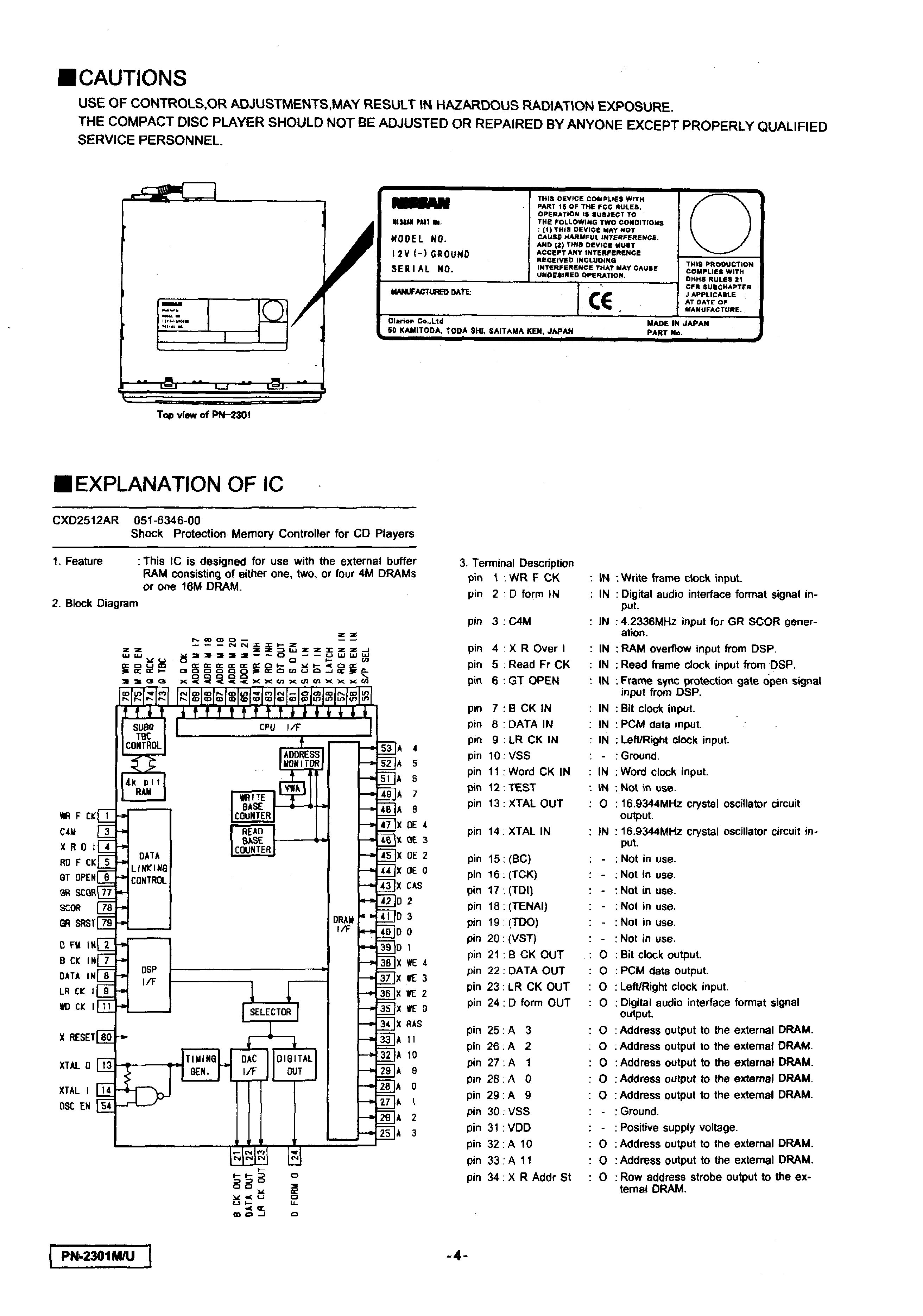
NOTE
We can not supply PWB with component parts in principle.
When a circuit on PWB has failure, please repair it by com-
ponent parts base. Parts which are not mentioned in ser-
vice manual are not supplied.
COMPONENTS
PN-2301M-A
Main unit
1
PN-2301U-B
Main unit
1
Parts bag
1
Machine screw(M5
8)
714-5008-41
4
Extention lead
854-7608-01
1
To engineers in charge of repair or
inspection of our products.
Before repair or inspection, make sure to follow
the instructions so that customers and Engineers
in charge of repair or inspection can avoid suf-
fering any risk or injury.
1. Use specified parts.
The system uses parts with special safety features against
fire and voltage. Use only parts with equivalent charac-
teristics when replacing them.
The use of unspecified parts shall be regarded as re-
modeling for which we shall not be liable. The onus of
product liability (PL) shall not be our responsibility in cases
where an accident or failure is as a result of unspecified
parts being used.
2. Place the parts and wiring back in their original positions
after replacement or re-wiring.
For proper circuit construction, use of insulation tubes,
bonding, gaps to PWB, etc, is involved. The wiring con-
nection and routing to the PWB are specially planned
using clamps to keep away from heated and high voltage
parts. Ensure that they are placed back in their original
positions after repair or inspection.
If extended damage is caused due to negligence during
repair, the legal responsibility shall be with the repairing
company.
3. Check for safety after repair.
Check that the screws, parts and wires are put back se-
curely in their original position after repair. Ensure for
safety reasons there is no possibility of secondary
ploblems around the repaired spots.
Model
page10 add the FPC part.2006 May
- 2 -
PN-2301M/U
If extended damage is caused due to negligence of re-
pair, the legal responsibility shall be with the repairing
company.
4. Caution in removal and making wiring connection to the
parts for the automobile.
Disconnect the battery terminal after turning the ignition
key off. If wrong wiring connections are made with the
battery connected, a short circuit and/or fire may occur.
If extensive damage is caused due to negligence of re-
pair, the legal responsibility shall be with the repairing
company.
5. Cautions regarding chips.
Do not reuse removed chips even when no abnormality
is observed in their appearance. Always replace them
with new ones. (The chip parts include resistors, capaci-
tors, diodes, transistors, etc). The negative pole of tanta-
lum capacitors is highly susceptible to heat, so use spe-
cial care when replacing them and check the operation
afterwards.
6. Cautions in handling flexible PWB
Before working with a soldering iron, make sure that the
iron tip temperature is around 270
. Take care not to
apply the iron tip repeatedly(more than three times)to the
same patterns. Also take care not to apply the tip with
force.
7. Turn the unit OFF during disassembly and parts replace-
ment. Recheck all work before you apply power to the
unit.
Chck the disc and replace it with a nondefective
disc.
8. Cautions in checking that the optical pickup lights up.
The laser is focused on the disc reflection surface through
the lens of the optical pickup. When checking that the
laser optical diode lights up, keep your eyes more than
30cms away from the lens. Prolonged viewing of the la-
ser within 30cms may damage your eyesight.
9. Cautions in handling the optical pickup
The laser diode of the optical pickup can be damaged by
electrostatic charge caused by your clothes and body.
Make sure to avoid electrostatic charges on your clothes
or body, or discharge static electricity before handling the
optical pickup.
9-1. Laser diode
The laser diode terminals are shorted for transpor-
tation in order to prevent electrostatic damage.
After replacement, open the shorted circuit. When
removing the pickup from the mechanism, short
the terminals by soldering them to prevent this
damage.
9-2. Actuator
The actuator has a powerful magnetic circuit. If a
magnetic material is put close to it. its characteris-
tics will change. Ensure that no foreign substances
enter through the ventilation slots in the cover.
9-3. Cleaning the lens
Dust on the optical lens affects performance. To
clean the lens, apply a small amount of isopropylalcohol
to lens paper and wipe the lens gently.
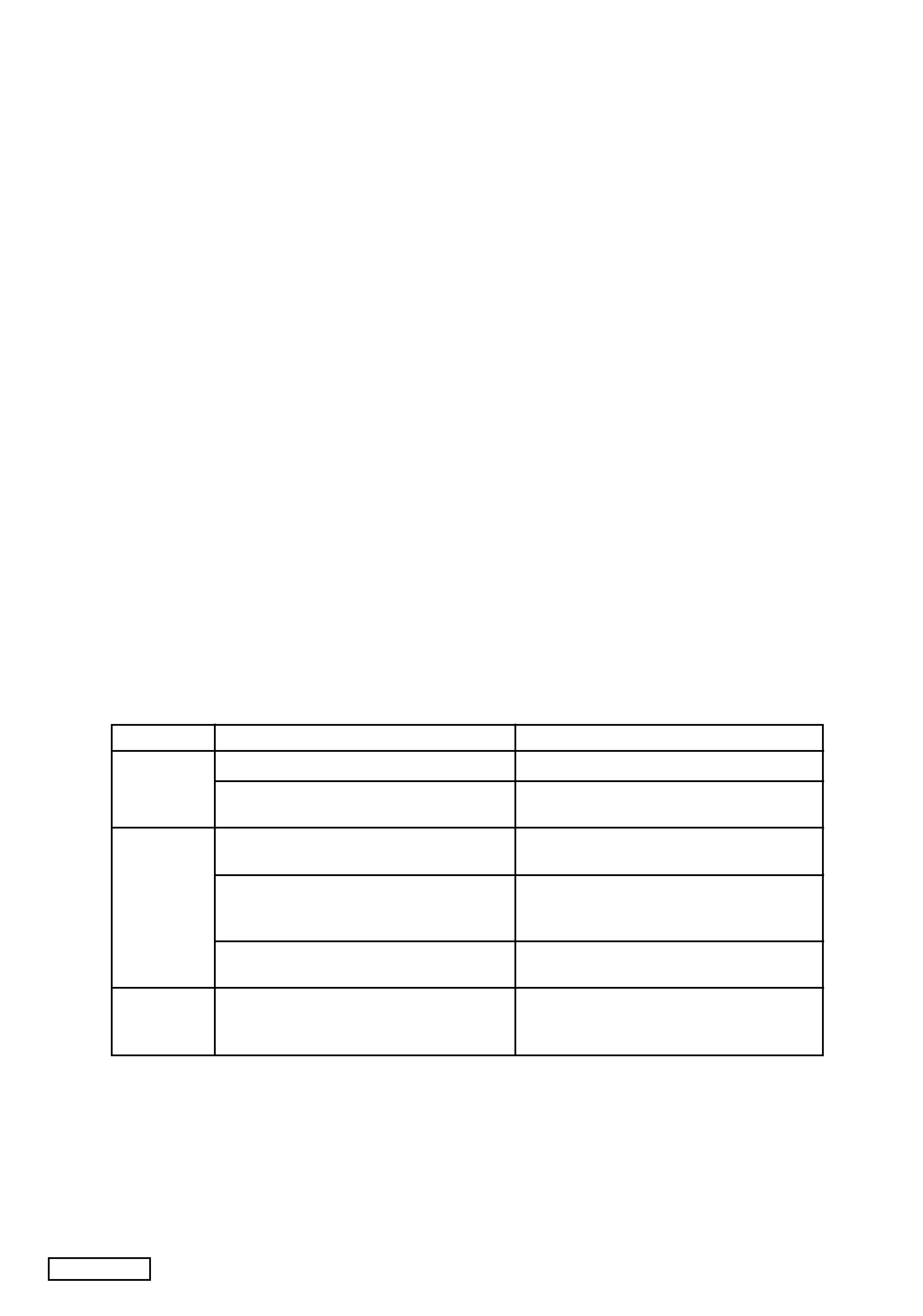
ERROR DISPLAYS
To protect the system,this unit has been equippedb with self diagnostic function.If a fault arises,a warning is issued by various error
displays.Follow the corrective measures and remove the fault.
Error Display
Err 1
Err 2
Err 3
Cause
The disc is dirty,warped or damaged,which pre-
vents the pickup from focuusing correctly.
Foreign matter in the disc insertion slot prevents
proper positioning of the disc.
All discs have been loaded upside down.
A disc was forced into the unit when the mes-
sage "WAIT" was displayed and loading can-
not be performed correctly.
The mechanism is damaged and disc cannot
be ejected or other symptoms are present.
The exterior of the disc is damaged and is de-
formed.
The disc is deformed.
Remedy
Eject the disc and load it with the correct side up.
Check the disc.
Remove foreign matter and eject the disc.
Turn on the power again.
If any other CDs are also loaded,eject all CDs.
The mechanism may have been damaged.
- 3 -
PN-2301M/U
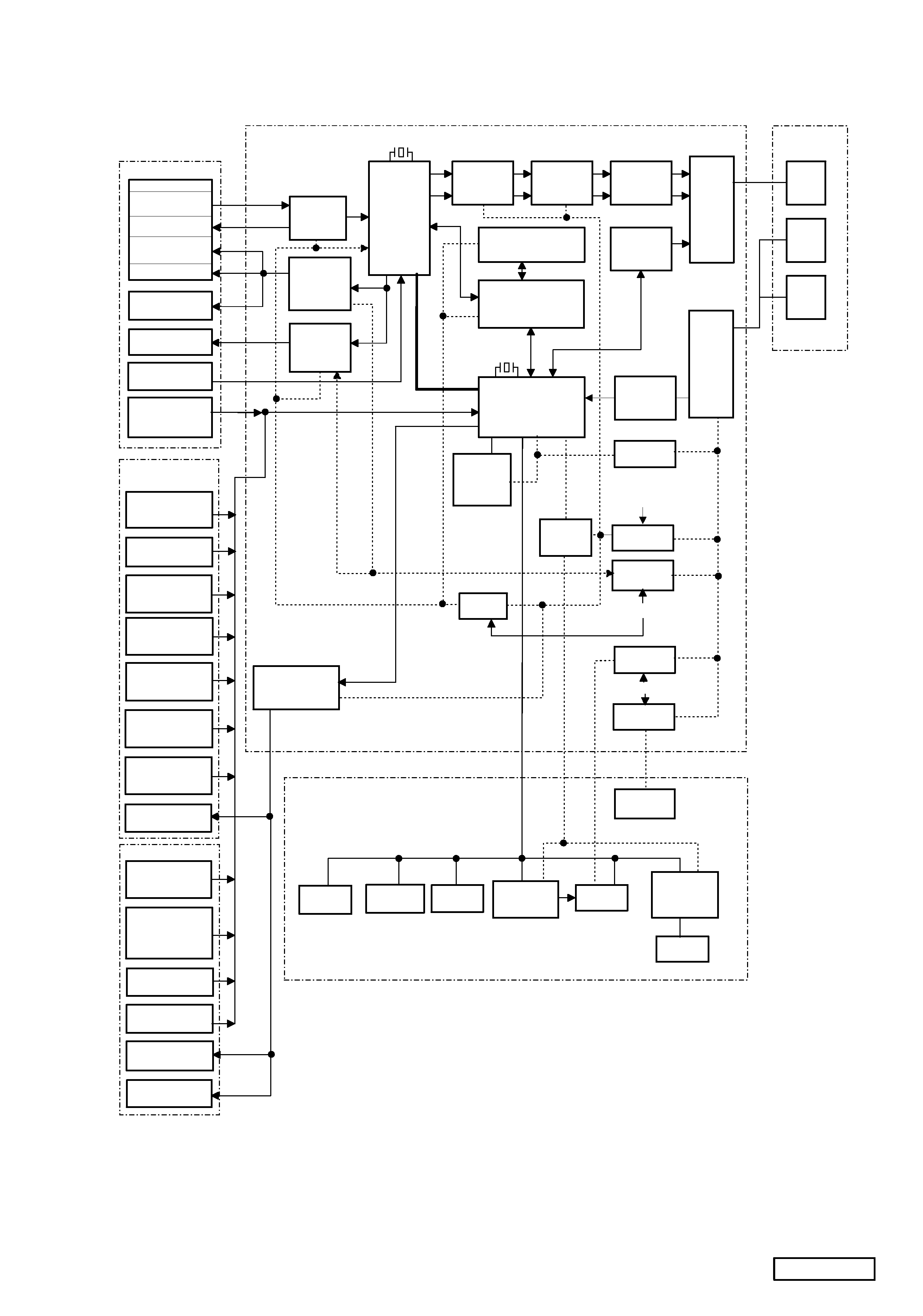
BLACK DIAGRAM
I N / O U T
C O N N E C T O R
D I N
( 8 P )
( 4 P )
( 2 P )
J3
03
C
O
N
N
E
C
TO
R
(7
P
)
J3
04
C
O
N
N
E
C
TO
R
(5
P
)
Q 3 0 9 , 3 1 0
M U T E
I C 3 0 2
N J M 4 5 5 6 A
B T L
I C 3 0 1
N J M 4 5 5 6 A
L P F
Q 3 0 2
A U X I / F
I C 1 1 0 D - R A M
M N 4 1 1 6 4 0 0
M A I N P W B
Q 2 0 6
I L L
C O N T R O L
I C 1 0 9
V D D 5 V
P - O N 1 ( F r o m C P U )
E X T E N T I O N L E A D
Q 3 0 4
A U D I O 9 V
Q 1 0 8
C D 8 V
P - O N 2 ( F r o m C P U )
Q 2 0 3
L E D 5 V
S Y S - O N ( F r o m C P U )
Q 1 0 5
P L + B
L C D
L A M P
I C 4 0 1
L C D D R I V E R
L C 7 5 8 2 2 W
L C D 4 0 1
L C D
L E D
D 4 0 1 - 4 0 8
I C 4 0 2
L E D D R I V E R
N J U 3 7 1 5
E S C U T C H E O N
X 4 0 1
B U Z Z E R
S 4 1 3
E J E C T S W
S 4 0 1 - 4 1 2
S W
I C 1 0 1 , 1 0 5 , 1 0 6
M O T O R D R I V E R
B A 6 9 1 9 P F
Q 1 1 5
C D 5 V
Q 3 0 7
V D D R E F
5 V
I C 2 0 2
R E S E T
A C C - D E T
N J M 2 1 0 3 M
I C 2 0 3
u P D 7 8 0 7 8
C P U
4 . 9 1 5 2 M H z
I C 1 0 2
S P I N D L E
D R I V E R
B A 6 8 4 9 F P
I C 1 0 3
S E R V O
D R I V E R
B A 5 9 2 9 F P
I C 1 0 7
D S P , S S P
D A C
C X D 2 5 4 8 R
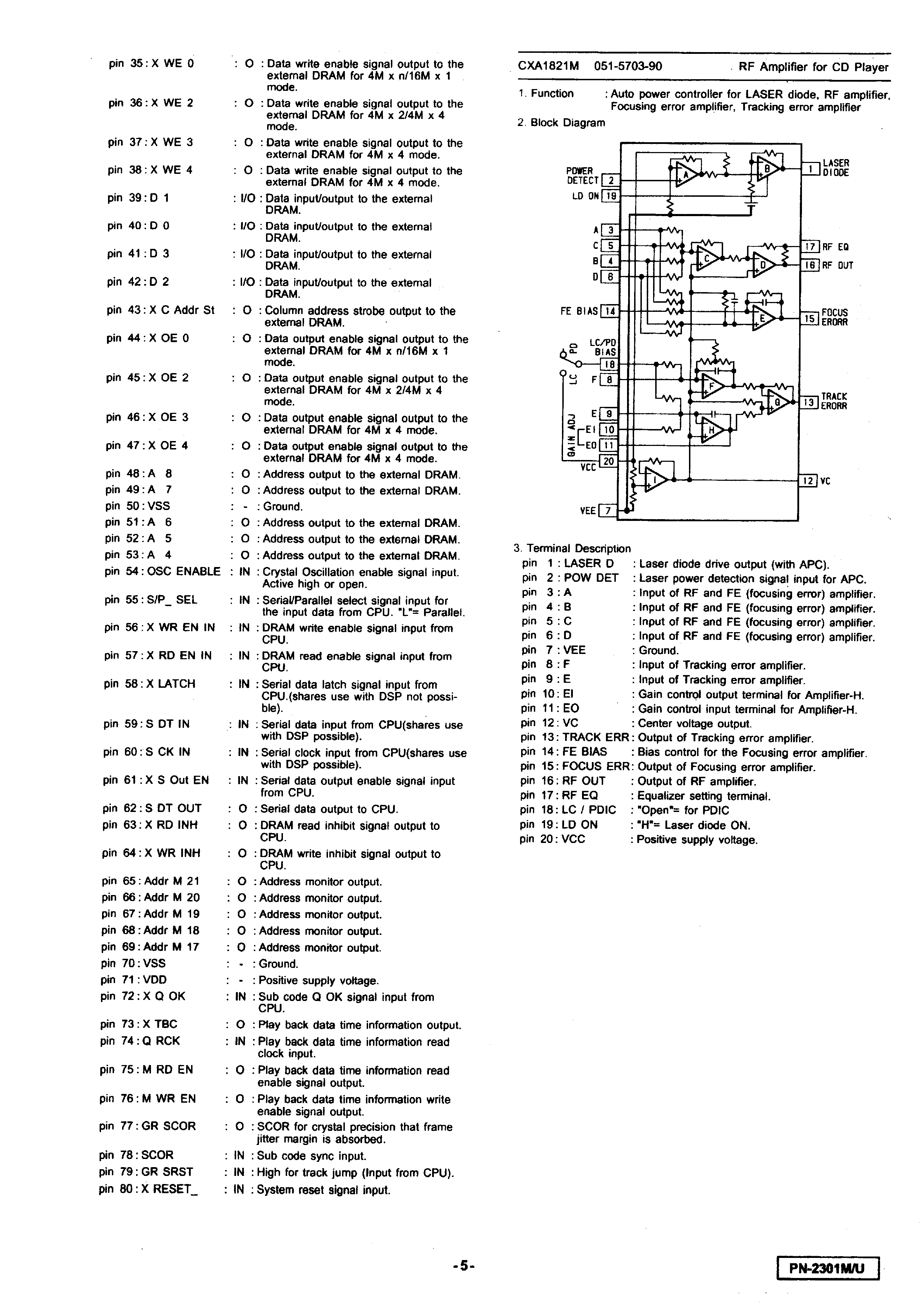
I C 1 0 8
S H O C K P R O O F M
C O N T R O L L E R
C X D 2 5 1 2 A R
1 6 . 9 3 4 M H z
I C 1 0 4
R F A M P
C X A 1 8 2 1 M
D R I V E U N I T
P I C K - U P
S T A G E U N I T
P H O T O
D E T E C T O R
L A S E R
T R A C K I N G
C O I L
F O C U S C O I L
M 4
T H R E A D M O T O R
M 5
S P I N D L E M O T O R
S W 7
L I M I T S W
S W 8
D I S C H O O K
R E L E A S E S W
M 3
L O A D I N G M O T O R
P T 8
S T O C K A R M
P H O T O I N T
S W 6
D R I V E U N I T
C H U - P O S I T I O N
S W 5
D R I V E U N I T
I N I T I A L P O S I T I O N
S W 4
D I S C S E L E C T O R
I N I T I A L
P T 2
D I S C S E L E C T O R
P O S I T I O N
M 1
S T A G E U / D
M 2
D I S C S E L E C T O R
S W 3
D O O R C L O S E
P T 4 , 5 , 6 , 7
L O A D I N G / E J E C T
P T 3
P L A Y P O S I T I O N
S W 2
E J E C T A R M E N D
S W 1
M O D E P L A T E
I N I T I A L
P O S I T I O N
P T 1
M O D E P L A T E
C O U N T
C H A S S I S U N I T